JP4515667B2 - Photo output device, photo output method, and photo output program - Google Patents
Photo output device, photo output method, and photo output program Download PDFInfo
- Publication number
- JP4515667B2 JP4515667B2 JP2001232542A JP2001232542A JP4515667B2 JP 4515667 B2 JP4515667 B2 JP 4515667B2 JP 2001232542 A JP2001232542 A JP 2001232542A JP 2001232542 A JP2001232542 A JP 2001232542A JP 4515667 B2 JP4515667 B2 JP 4515667B2
- Authority
- JP
- Japan
- Prior art keywords
- image
- photographed
- input
- pen input
- display
- Prior art date
- Legal status (The legal status is an assumption and is not a legal conclusion. Google has not performed a legal analysis and makes no representation as to the accuracy of the status listed.)
- Expired - Lifetime
Links
Images


Description
【0001】
【発明の属する技術分野】
本発明は、ゲームセンター等に設置され、硬貨等の投入により使用者を撮影し、撮影画像をプリントして販売する写真出力装置、写真出力方法ならびに写真出力プログラムに関するものである。
【0002】
【従来の技術】
近年、ゲームセンター等において、写真を撮影してシールプリント等にする写真自販機が数多く設置されている。このような写真自販機としては、一般に、図13に示すようなものが用いられている。このものは、本体52の内部に、略45°の角度をもってハーフミラー53が設けられている。このハーフミラー53の奥に、使用者54を撮影するカメラ55が設けられ、ハーフミラー53の下方には、上記カメラ55で撮影された画像を表示するモニタ56が設けられている。図において51はコントローラ、57は写真プリント58を印刷するプリンタである。
【0003】
上記写真自販機では、ハーフミラー53を透してカメラ55で撮影された画像がモニタ56に表示され、このモニタ56に表示された画像がハーフミラー53に反射して使用者54によって確認できるようになっている。そして、使用者54は、モニタ56に映った自分の姿を確認しながら所望のポーズをとり、好みのところでコントローラ51を操作して静止画を撮影することが行われる。そして、この静止画は、適当なフレームや前景の画像と合成されて写真プリント58として印刷される。
【0004】
【発明が解決しようとする課題】
しかしながら、上記写真自販機では、カメラ55で撮影した写真をシール等の写真プリント58として、その場で出力できるにすぎない。最近では、写真自販機利用人口の増加とともに、そのニーズも多様化している。そこで、これらのニーズに応えるため、使用者54の画像に合成されるフレームや前景として各種の趣向を凝らしたものも数多く提供されているが、単にその場で写真プリント58として出力するだけの画一的なものでは満足されなくなってきている。
【0005】
そこで、最近では、カメラで撮影した画像をメモリに固定して液晶タブレット等に表示し、表示された固定画像にタッチペン等で手書き画像を入力して上記固定画像に合成する写真自販機も考案され実用化されている。
【0006】
上記写真自販機では、一旦撮影画像を静止画として固定してこの1枚の撮影画像に手書き画像を入力し合成してプリントするため、1回のプレイでは手書き画像が合成された撮影画像が1枚得られるにすぎない。ところが、1回のプレイで納得のいく撮影画像や手書き画像の入力を行なえればよいが、必ずしもそのような場合ばかりとは限らず、十分に納得できないままプレイが終了して画像がプリントアウトされてしまうこともしばしば起こりうる。このような場合、使用者としては、十分な満足を得ることができず、納得できるプリントを得るためには再び最初からプレイをやり直さなければならないため、時間も費用も同じだけかかり、無駄が多かった。一方、ゲームセンター等にとっては、同じ使用者に連続プレイをされると、それだけ顧客の回転率が悪くなって顧客に不満を与えかねない。
【0007】
本発明は、このような事情に鑑みなされたもので、複数の撮影画像に同時に手書き画像等の第2画像の入力を行なえる写真出力装置、写真出力方法ならびに写真出力プログラムの提供を目的とする。
【0008】
【課題を解決するための手段】
上記の目的を達成するため、本発明の写真出力装置は、使用者を含む被写体を撮影してその写真を出力する写真出力装置であって、
被写体を撮影して撮影画像を得る撮影手段と、上記撮影手段で撮影された撮影画像を表示するディスプレイと、使用者の操作により上記撮影画像と合成される手書き画像を含むペン入力画像を入力するペン入力手段と、上記撮影画像とペン入力画像を合成する画像合成手段と、撮影画像とペン入力画像との合成画像を印刷出力する印刷手段とを備え、
上記ディスプレイに撮影画像を同時に複数並べて表示するとともに、上記ペン入力手段により上記並べて表示された複数の撮影画像の境界をまたぐようにペン入力画像を入力しうるようになっており、
さらに、ペン入力画像を入力する際にディスプレイに並べて表示されて境界をまたいでペン入力画像が入力された複数の撮影画像にかかる合成画像を、上記印刷手段により、共通の台紙上に別々の写真として出力するか、上記台紙上に並べて1つの写真として出力するか、少なくともいずれかを行うように構成されていることを要旨とする。
【0009】
また、上記目的を達成するため、本発明の写真出力方法は、使用者を含む被写体を撮影してその写真を出力する写真出力方法であって、
被写体を撮影して撮影画像を得る撮影ステップと、上記撮影ステップで撮影された撮影画像をディスプレイに表示する画像表示ステップと、使用者の操作により上記撮影画像と合成される手書き画像を含むペン入力画像の入力を受け付けるペン入力ステップと、上記撮影画像とペン入力画像を合成する画像合成ステップと、撮影画像とペン入力画像との合成画像を印刷出力する印刷ステップとを備え、
上記ディスプレイに撮影画像を同時に複数並べて表示するとともに、上記ペン入力手段により上記並べて表示された複数の撮影画像の境界をまたぐようにペン入力画像を入力しうるようにしており、
さらに、ペン入力画像を入力する際にディスプレイに並べて表示されて境界をまたいでペン入力画像が入力された複数の撮影画像にかかる合成画像を、上記印刷手段により、共通の台紙上に別々の写真として出力するか、上記台紙上に並べて1つの写真として出力するか、少なくともいずれかを行うことを要旨とする。
【0010】
また、上記目的を達成するため、本発明の写真出力プログラムは、使用者を含む被写体を撮影してその写真を出力する写真出力プログラムであって、
被写体を撮影して撮影画像を得る撮影ステップと、上記撮影ステップで撮影された撮影画像をディスプレイに表示する画像表示ステップと、使用者の操作により上記撮影画像と合成される手書き画像を含むペン入力画像の入力を受け付けるペン入力ステップと、上記撮影画像とペン入力画像を合成する画像合成ステップと、撮影画像とペン入力画像との合成画像を印刷出力する印刷ステップとを備え、
上記ディスプレイに撮影画像を同時に複数並べて表示するとともに、上記ペン入力手段により上記並べて表示された複数の撮影画像の境界をまたぐようにペン入力画像を入力しうるステップとをコンピュータ装置に実行させ、
さらに、ペン入力画像を入力する際にディスプレイに並べて表示されて境界をまたいでペン入力画像が入力された複数の撮影画像にかかる合成画像を、上記印刷手段により、共通の台紙上に別々の写真として出力するか、上記台紙上に並べて1つの写真として出力するか、少なくともいずれかを行うステップをコンピュータ装置に実行させることを要旨とする。
【0011】
すなわち、本発明は、ディスプレイに撮影画像を同時に複数表示するとともに、ペン入力手段により上記複数の撮影画像に合成されるペン入力画像を入力するようになっているため、複数の撮影画像に同時に手書き画像等のペン入力画像の入力を行なえる。したがって、1回のプレイで使用者が納得できる撮影画像やペン入力画像を得やすく、使用者の満足度が高くなる。このため、プレイのやり直しの必要性が低下し、使用者にとっては時間と費用の節約となり、ゲームセンター等にとっては顧客の回転率の低下を防止できる。また、複数の撮影画像を並べてディスプレイに表示するようになっていることから、複数の撮影画像を見比べながらペン入力画像の入力ができる。しかも、並べて表示された撮影画像の境界をまたぐようにペン入力画像を入力しうるようになっているため、並べて表示された撮影画像の境界をまたぐようにペン入力画像が合成された写真が得られる。
また、さらに、ペン入力画像を入力する際にディスプレイに並べて表示されて境界をまたいでペン入力画像が入力された複数の撮影画像にかかる合成画像を、上記印刷手段により、共通の台紙上に別々の写真として出力するか、上記台紙上に並べて1つの写真として出力するか、少なくともいずれかを行うため、複数の撮影画像にかかる合成画像が共通の台紙上に別々の写真として出力されたプリントが得られ、複数の撮影画像にかかる合成画像が台紙上に1つの写真として出力されたプリントが得られる。
【0017】
【発明の実施の形態】
つぎに、本発明の実施の形態を詳しく説明する。
【0018】
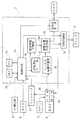
図1は、本発明の写真自販機の一実施の形態を示す図である。この写真自販機は、内部および表面に各種の装置が設けられた筐体1と、上記筐体1の上下から被写体2の背後まで達するように突き出された支柱3とを備えている。そして、上記両支柱3の先端部分に、撮影の際の背景となるカーテン5が吊設され、上記筐体1,支柱3,カーテン5で囲まれた空間が、被写体2の撮影用ブースを形成している。上側の支柱3には、撮影用ブース内の被写体2を照射する2つのライト4が取り付けられている。
【0019】
上記筐体1の内部には、被写体2を撮影するカメラ6が設けられている。上記筐体1のカメラ6の被写体2側に位置する面には、透明板10が嵌め込まれている。また、上記筐体1の内部には、上記カメラ6から画像データを受信して画像合成等の処理を行なうコンピュータ装置7が設けられている。
【0020】
また、上記筐体1の被写体2側には、上記コンピュータ装置7から送信された合成画像等の画像信号を受信して画像を表示するディスプレイ8が設けられている。さらに、上記筐体1の内部には、コンピュータ装置7から送信された画像データを受信し、この画像を印刷媒体15に印刷するプリンタ9が設けられている。このプリンタ9で印刷された印刷媒体15は、筐体1前面に形成された送出口19から送出されるようになっている。
【0021】
さらに、上記筐体1の被写体2側には操作パネルが設けられ、この操作パネルにコントローラ11が設けられている。上記コントローラ11は、タッチペン12を備えており、使用者2がディスプレイ8に表示される操作指示に従ってディスプレイ8の表面をタッチペン12でタップ(軽く叩く)等することにより、各種の操作信号がコンピュータ装置7に送られ、後述する各種の操作が行なわれるようになっている。
【0022】
また、上記タッチペン12は、その先端をディスプレイ8の表面に接触させて文字や図形等を描いて入力しうるようになっており、手書き入力された文字・図形等の画像データやスタンプ画像等が、カメラ6で撮影された被写体2の撮影画像と合成されてディスプレイ8に表示され、その合成画像が印刷媒体15に印刷されるようになっている。
【0023】
また、上記タッチペン12は、ディスプレイ8に表示される指示に従って、使用者2が操作することによりアンケートを入力しうるようになっており、入力されたアンケートの結果を外部に送信しうるようになっている。
【0024】
また、筐体1の前面には、対価としてのコインを投入するコイン投入口(図示せず)が設けられ、筐体1内部のコイン投入口に隣接した位置に、投入されたコインを検出してコンピュータ装置7に検出信号を送信するコイン検出部17(図2参照)が設けられている。また、筐体1前面の適所には、コンピュータ装置7から音声信号を受信して出力するスピーカ(図示せず)が設けられている。
【0025】
この例において、使用者2がディスプレイ8から見る画像およびプリンタ9から印刷される画像は、被写体2の撮影像と、タッチペン12による手書き入力画像等とが合成されたものである。
【0026】
つぎに、上記コンピュータ装置7のシステム構成について詳しく説明する。
【0027】
図2に示すように、コンピュータ装置7は、タッチペン12によりディスプレイ8の入力部35に入力された各種の操作信号をコントローラ11を介して受信し、受信した操作信号に応じて各種制御を行なう制御手段31を備えている。上記制御手段31は、コイン検出部17からの検出信号を受信することにより、撮影等の制御を開始するようになっている。
【0028】
上記ディスプレイ8には、タッチペン12によって手書き画像や操作信号が入力される入力部35と、画像等を表示する表示部36とが設けられている。上記タッチペン12で入力された手書き画像等は、ペン入力画像記憶部32に記憶され、記憶された手書き画像等のデータは、後述する複数画像合成手段30に送られる。また、タッチペン12によって入力された操作信号は、コントローラ11を介して制御手段31に送られ、各種の制御が行なわれる。
【0029】
上記コンピュータ装置7には、タッチペン12によるペン入力画像の入力可能時間を計測するタイマ26が設けられている。上記タイマ26は、制御手段31による手書き画像開始の指示メッセージをディスプレイ8に表示させるのとほぼ同時に計測を開始する。上記タイマ26の計測時間があらかじめ設定された所定の入力可能時間(例えば90秒等)に達したときに手書き画像等の入力を停止してつぎの動作に移るようになっている。
【0030】
そして、上記コンピュータ装置7には固定画像記憶部38が設けられ、上記被写体2によるタッチペン12の操作により所望のシャッタタイミングで撮像映像を静止画像として固定するようになっている。また、上記コンピュータ装置7には、シャッタ操作によるカメラ6での撮影回数をカウントするカウンタ25が設けられている。上記カウンタ25は、コイン検出部17による最初のコインの検出によってリセットされてカウントを開始する。上記カウンタ25のカウントがあらかじめ設定された所定の撮影可能回数(例えば4回等)に達するまで、一定の時間間隔で撮影を繰り返し、複数の撮影画像(静止画像)を得るようになっている。
【0031】
上記複数の撮影画像は、ディスプレイ8の表示部36に一覧表示されて使用者2に対してプレビュー確認させるようになっている。そして、上記コンピュータ装置7には、画像選択手段37が設けられ、上記一覧表示された複数の撮影画像のなかから使用者がタッチペン12を操作して好みの画像を選択するようになっている。このとき選択される画像はひとつでもよいし複数でもよい。そして、上記画像選択手段37で選択された撮影画像は、ディスプレイ8の表示部36に並べて表示され、この状態で手書き画像の入力が行なわれる。
【0032】
さらに、上記コンピュータ装置7には複数画像合成手段30が設けられ、上記画像選択手段37で選択され固定画像記憶部38に固定された静止画像に、タッチペン12によってディスプレイ8の入力部35に入力され、ペン入力画像記憶部32に記憶された文字や図形等の手書き画像等を合成するようになっている。上記複数画像合成手段30で合成された合成画像は、ディスプレイ8の表示部36に表示されるようになっている。
【0033】
また、上記コンピュータ装置7には、送受信手段39が設けられている。上記送受信手段39は、例えばインターネット等の通信回線(NET)に接続され、撮影画像や合成画像を上記通信回線を介して外部に出力し、外部のサーバに格納したり端末装置等に出力して表示したり印刷したりできるようになっている。
【0034】
さらに、上記コンピュータ装置7は、プリンタ9による印刷を制御する印刷制御部34を備えている。上記印刷制御部34は、使用者2によるタッチペン12の操作によって選択されたシートレイアウトにより、印刷媒体15に合成画像を印刷するよう制御する。このとき、使用者2による指示により、手書き画像入力の際に並べて表示された撮影画像を1枚の写真として印刷したり、別々の写真として印刷することが行なわれる。
【0035】
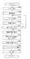
上記写真自販機の動作の一例について、図3のフローチャートを参照しながら説明する。ここで、図3において、「S」はステップを意味する。
【0036】
まず、使用者2が最初のコインを投入すると(S100)、カメラ6による被写体2の撮像が開始され(S110)、ディスプレイ8の表示部36に撮像映像が動画としてリアルタイムで表示される。
【0037】
ついで、使用者2がディスプレイ8の表示画像を見ながら被写体2の位置調整を完了した後に、タッチペン12を用いて画面の指示に従ってシャッタ操作の操作信号を入力すると(S120)、使用者2にポーズをとるよう指示し、それから所定時間のカウントダウン後に、所定の瞬間の撮像映像が固定画像記憶部38に固定される(S130)。このとき、ディスプレイ8には、そのときの撮影画像が静止画像として表示される。
【0038】
つぎに、カウンタ25が規定の撮影枚数のカウントに達しているか否かにより、規定の枚数に達していなければステップ120に戻ってシャッタ操作と画像の固定を繰り返し、規定の枚数に達していればつぎのステップに進む(S140)。
【0039】
ステップ140において、規定の撮影回数に達していれば、図4に示すように、全ての撮影画像22a,22b,22c,22dの一覧をディスプレイ8に表示して使用者2に対して好みの画像の選択を促す(S150)。この例では、4回のシャッタ操作により撮影された4枚の撮影画像が表示されている。また、この例では、4人の被写体A,B,C,Dが、AとB,CとD,AとC,BとDのそれぞれ2人ずつのペアになって交代で撮影を行なっている。
【0040】
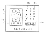
ついで、使用者2は、タッチペン12の先端で好みの画像をタップすることにより、撮影画像の選択を行なう(S160)。撮影画像の選択が行なわれると、図5に示すように、選択された撮影画像22a,22bがディスプレイ8の表示部36に並べて表示される(S170)。この状態で、タッチペン12を操作することにより手書き画像等の入力が行なわれる。
【0041】
図5の手書き画像入力画面において、21a,21b,21cは、それぞれ手書きペン,スタンプ画像,アルファベット文字を入力する際にタッチペン12でタップするアイコンである。
【0042】
手書き画像27を入力する際には、手書きペンのアイコン21aをタッチペン12の先端でタップしてから、タッチペン12の先端を、並べて表示された撮影画像22a,22bの上に接触させて絵や文字を描くことにより、手書き画像27の入力が行なわれる。
【0043】
スタンプ画像28を入力する際には、スタンプ画像のアイコン21bをタッチペン12の先端でタップしてから、タッチペン12の先端を、並べて表示された撮影画像22a,22bの上に接触させることにより、スタンプ画像28の入力が行なわれる。
【0044】
アルファベット文字を入力する際には、アルファベット文字のアイコン21cをタッチペン12の先端でタップしてから、タッチペン12の先端を、並べて表示された撮影画像22a,22bの上に接触させることにより、アルファベット文字の入力が行なわれる。
【0045】
このようにして、手書き画像27やスタンプ画像28等が入力され、図6に示すように、並べて表示された撮影画像22a,22bの上に合成される(S180)。このとき、上記手書き画像27やスタンプ画像28は、ふたつの撮影画像22a,22bの境界線29をまたぐように入力され合成されるようになっている。
【0046】
そして、手書き画像等の入力は、タイマ26の計測時間があらかじめ設定された所定の入力可能時間(例えば90秒等)に達するまで続けられる。入力可能時間に達すると、手書き画像等の入力が停止され、印刷の際のシートレイアウトの選択が行なわれる(S190)。ここでは、シートレイアウトの選択を促す画面が表示され、使用者2は、シールプリントかカードプリントか、シールプリントの場合は何枚のシールにするか等の選択をタッチペン12により行なう。
【0047】
ついで、シートレイアウトの選択が終了すると、合成画像の画像データがプリンタ9に送られ、印刷が開始される(S200)。そして、被写体2の撮影画像とペン入力画像等が合成された合成画像が印刷された印刷媒体15が送出される。
【0048】
このとき、使用者2の選択により、図7に示すように、手書き画像27等の入力画面(図5および図6参照)において並べて表示された撮影画像22a,22bの境界線29を消して、2枚の撮影画像22a,22bを1枚のシールプリント24に印刷することが行なわれる。図において23はシール台紙である。
【0049】
また、使用者2の選択により、図8に示すように、手書き画像27等の入力画面(図5および図6参照)において並べて表示された2枚の撮影画像22a,22bを別々のシールプリント24に印刷することも行なわれる。
【0050】
このように、上記写真自販機によれば、複数の撮影画像22a,22bに同時にそれぞれ手書き画像27等の入力を行なえるため、1回のプレイで使用者2が納得できる撮影画像22a,22bや手書き画像27を得やすく、使用者2の満足度が高くなる。このため、プレイのやり直しの必要性が低下し、使用者2にとっては時間と費用の節約となり、ゲームセンター等にとっては顧客の回転率の低下を防止できる。
【0051】
なお、上記写真自販機では、合成画像を印刷するかわりに、送受信手段39により通信回線を介して外部に出力し、外部のサーバに格納したり端末装置等に出力して表示したり、あるいは外部で印刷したりすることもできる。
【0052】
また、上記写真自販機では、カメラ6での撮影回数をカウンタ25でカウントし、あらかじめ設定された撮影可能回数に達したときに、撮影画像の選択を行なうようにしたが、これに限定するものではなく、カメラ6での撮影可能時間をタイマ26で計測し、あらかじめ設定された撮影可能時間に達したときに、撮影画像の選択を行なうようにしてもよい。
【0053】
図9は、本発明の第2の実施の形態の写真自販機である。この写真自販機では、複数回の撮影による複数の撮影画像から好みの画像を選択するのではなく、1つの撮影画像を複写して、複写された複数の画像をディスプレイ8に並べて表示し、手書き画像27等の入力を行なうようになっている。すなわち、この写真自販機では、画像選択手段37に換えて画像複写手段40が設けられ、固定画像記憶部38に固定された撮影画像を複数に複写するようになっている。それ以外は、上記第1の実施の形態と同様であり、同様の部分には同じ符号を付している。
【0054】
上記写真自販機の動作の一例について、図10のフローチャートを参照しながら説明する。ここで、図10において、「S」はステップを意味する。
【0055】
まず、使用者2が最初のコインを投入すると(S100)、カメラ6による被写体2の撮像が開始され(S110)、ディスプレイ8の表示部36に撮像映像が動画としてリアルタイムで表示される。
【0056】
ついで、使用者2がディスプレイ8の表示画像を見ながら被写体2の位置調整を完了した後に、タッチペン12を用いて画面の指示に従ってシャッタ操作の操作信号を入力すると(S120)、使用者2にポーズをとるよう指示し、それから所定時間のカウントダウン後に、所定の瞬間の撮像映像が固定画像記憶部38に固定される(S130)。このとき、ディスプレイ8には、そのときの撮影画像が静止画像として表示される。
【0057】
そして、固定された静止画像をディスプレイ8の表示部36に表示して使用者2に対してプレビュー確認させ、ディスプレイ8にはプレビューを確認させた静止画像について撮りなおしを希望するか否かの選択を促すメッセージを表示する(S145)。
【0058】
ステップ145において、使用者2が撮りなおしを希望する場合は、タッチペン12でキャンセル操作を行なってステップ120に戻り、再度シャッタ操作を行なうようになっている。
【0059】
ステップ145において、撮りなおしを行なわない場合は、固定された静止画像を複写し(S165)、図11に示すように、複写された複数の撮影画像22aがディスプレイ8の表示部36に並べて表示される(S175)。この状態で、タッチペン12を操作することにより手書き画像等の入力が行なわれる(S180)。
【0060】
そして、手書き画像等の入力は、タイマ26の計測時間があらかじめ設定された所定の入力可能時間(例えば90秒等)に達するまで続けられる。入力可能時間に達すると、手書き画像等の入力が停止され、印刷の際のシートレイアウトの選択が行なわれる(S190)。ここでは、シートレイアウトの選択を促す画面が表示され、使用者2は、シールプリントかカードプリントか、シールプリントの場合は何枚のシールにするか等の選択をタッチペン12により行なう。
【0061】
ついで、シートレイアウトの選択が終了すると、合成画像の画像データがプリンタ9に送られ、印刷が開始される(S200)。そして、被写体2の撮影画像とペン入力画像等が合成された合成画像が印刷された印刷媒体15が送出される。この写真自販機でも、上記第1の実施の形態と同様の作用効果を奏する。
【0062】
図12は、シートレイアウトの他の例を示す。この例では、3つの撮影画像を横に並べて手書き画像27等の入力を行い、境界線29を消して3つの撮影画像にかかる合成画像を並べて1枚のシールプリント24に印刷している。このようにすることにより、小さな筐体1の小さな撮影用ブースにおいて交代で撮影することにより、多人数が並んだパノラマのような写真を得ることができる(この例では2人ずつ3回撮影して6人が並んだ写真を得ている)。
【0063】
なお、上記各実施の形態では、コインの投入により撮影を開始し、追加コインの投入により撮影可能回数の追加や手書き画像入力可能時間の延長を行なうようにしたが、これに限定するものではなく、紙幣,プリペイドカード,メダル,クレジットカード,キャッシュカード等、撮影の対価として支払いうるものであれば、各種の態様を含む趣旨である。また、これらは、単独で用いる場合だけでなく、組み合わせて用いる場合も含む趣旨である。
【0064】
また、上記各実施の形態では、カメラ6での撮像映像とペン入力画像等とのふたつの画像を合成するようにしたが、これに限定するものではなく、これらの画像に、さらに前景や背景等になるフレーム画像を合成するようにしてもよい。
【0065】
また、上記実施の形態において、撮影を複数回行なって複数の撮影画像から使用者が好みの画像を選択するとともに、選択した画像の少なくとも1枚を複写するようにしてもよい。さらに、上記各実施の形態において、並べて同時に表示する撮影画像は、2枚に限定するものではなく、3枚以上にしてもよい。
【0066】
また、上記実施の形態において、カメラ6としては、デジタルカメラを用いることもできるし、ビデオカメラを用いることもでき、撮影画像を電気信号に変換しうるものであれば特に限定するものではなく、各種のものを用いることができる。さらに、上記実施の形態では、1台のカメラ6を備えた例を示したが、これに限定するものではなく、複数台のカメラ6を備えるようにしても差し支えない。
【0067】
また、上記実施の形態では、スタンプ画像は、スタンプ画像格納部(図示せず)に格納されたものを用いるようにしたが、これに限定するものではなく、フロッピディスク、CD−ROM,CD−R、光磁気ディスク等の各種の記憶媒体に記憶された画像データを読取って使用するようにすることもできる。
【0068】
また、上記実施の形態において、外部端末としては、例えば、携帯電話,コンピュータ装置,ファクシミリ装置,携帯情報端末等を用いることができる。これらの外部端末は普及率が高く、容易かつ安価にデータの送受信を行うことができる。また、上記外部端末として携帯電話を用いる場合、800MHzアナログ方式,800MHzデジタル方式,1.5GHzデジタル方式の各種携帯電話や、簡易型携帯電話(PHS)等を用いることができるが、携帯して移動可能な電話であれば、各種のものを用いることができる。
【0069】
また、上記実施の形態では、インターネットを介してデータを送受信する例を示したが、インターネット以外の通信回線として、例えば、アナログ電話回線,高速デジタル回線(ISDN回線),無線,光ファイバ,携帯電話回線(例えば、DoPa等),ZAQ,PHS回線(例えば、PIAFS,αDATA32等),総合知的通信網(UICN),新高度情報通信(VI&P),衛生通信回線,有線放送,各種通信ケーブルによるデータ通信やデータ転送等があげられるが、これら以外の各種のものも用いることができる。また、接続は、常時接続であると、そのつどダイヤルアップして接続するものであるとを問わない。
【0070】
【発明の効果】
以上のように、本発明によれば、複数の撮影画像に同時に手書き画像等のペン入力画像の入力を行なえる。したがって、1回のプレイで使用者が納得できる撮影画像やペン入力画像を得やすく、使用者の満足度が高くなる。このため、プレイのやり直しの必要性が低下し、使用者にとっては時間と費用の節約となり、ゲームセンター等にとっては顧客の回転率の低下を防止できる。また、複数の撮影画像を並べてディスプレイに表示するようになっていることから、複数の撮影画像を見比べながらペン入力画像の入力ができる。しかも、並べて表示された撮影画像の境界をまたぐようにペン入力画像を入力しうるようになっているため、並べて表示された撮影画像の境界をまたぐようにペン入力画像が合成された写真が得られる。
また、さらに、ペン入力画像を入力する際にディスプレイに並べて表示されて境界をまたいでペン入力画像が入力された複数の撮影画像にかかる合成画像を、上記印刷手段により、共通の台紙上に別々の写真として出力するか、上記台紙上に並べて1つの写真として出力するか、少なくともいずれかを行うため、複数の撮影画像にかかる合成画像が共通の台紙上に別々の写真として出力されたプリントが得られ、複数の撮影画像にかかる合成画像が台紙上に1つの写真として出力されたプリントが得られる。
【図面の簡単な説明】
【図1】本発明の写真自販機の一実施の形態を示す断面図である。
【図2】コンピュータ装置のシステム構成図である。
【図3】上記写真自販機の動作を説明するフローチャート図である。
【図4】撮影画像の選択画面を示す図である。
【図5】手書き画像の入力画面を示す図である。
【図6】手書き画像の入力画面を示す図である。
【図7】合成画像をシールプリントに出力した状態を示す図である。
【図8】合成画像をシールプリントに出力した状態を示す図である。
【図9】本発明の写真自販機の第2の実施の形態に用いるコンピュータ装置のシステム構成図である。
【図10】上記写真自販機の動作を説明するフローチャート図である。
【図11】手書き画像の入力画面を示す図である。
【図12】合成画像をシールプリントに出力した状態を示す図である。
【図13】従来例を示す断面図である。
【符号の説明】
6 カメラ
8 ディスプレイ
9 プリンタ
12 タッチペン
30 複数画像合成手段[0001]
BACKGROUND OF THE INVENTION
The present invention is a photograph that is installed in a game center or the like, photographs a user by inserting coins, and prints and sells the photographed image.OUTPUT DEVICE, PHOTO OUTPUT METHOD, AND PHOTO OUTPUT PROGRAMIt is about.
[0002]
[Prior art]
In recent years, a large number of photo vending machines that take photographs and make sticker prints have been installed in game centers and the like. As such a photo vending machine, the one shown in FIG. 13 is generally used. In this device, a
[0003]
In the photo vending machine, an image taken by the
[0004]
[Problems to be solved by the invention]
However, the photo vending machine can only output the photograph taken by the
[0005]
Therefore, recently, a photo vending machine has also been devised and put into practical use, in which an image taken with a camera is fixed in a memory and displayed on a liquid crystal tablet, etc., and a handwritten image is input to the displayed fixed image with a touch pen etc. It has become.
[0006]
In the above-mentioned photo vending machine, a photographed image is once fixed as a still image, and a handwritten image is input to this one photographed image and combined and printed. Therefore, one photographed image in which the handwritten image is synthesized in one play. It is only obtained. However, it is only necessary to input a photographed image or a handwritten image that is satisfactory in one play, but this is not always the case, and the play ends and the image is printed out without being fully satisfied. Can often occur. In such a case, the user cannot obtain sufficient satisfaction, and must play again from the beginning in order to obtain a satisfactory print. It was. On the other hand, for a game center or the like, if the same user plays continuously, the turnover rate of the customer becomes worse and the customer may be dissatisfied.
[0007]
The present invention has been made in view of such circumstances, and is a photograph capable of simultaneously inputting a second image such as a handwritten image on a plurality of photographed images.OUTPUT DEVICE, PHOTO OUTPUT METHOD, AND PHOTO OUTPUT PROGRAMThe purpose is to provide.
[0008]
[Means for Solving the Problems]
In order to achieve the above object, a photo output device of the present invention is a photo output device for photographing a subject including a user and outputting the photo,
A photographing unit for photographing a subject to obtain a photographed image, a display for displaying the photographed image photographed by the photographing unit, and a pen input image including a handwritten image synthesized with the photographed image by a user operation are input. A pen input means, an image composition means for composing the photographed image and the pen input image, and a print means for printing out a composite image of the photographed image and the pen input image,
A plurality of photographed images are displayed side by side on the display, and a pen input image can be input across the boundaries of the plurality of photographed images displayed side by side by the pen input means.And
Furthermore, when the pen input image is input, the combined images of the plurality of photographed images that are displayed side by side on the display and input the pen input image across the boundary are separated on a common mount by the printing unit. Or output as a single photo arranged on the above mount, or at least one of themIt is a summary.
[0009]
In order to achieve the above object, a photo output method of the present invention is a photo output method for photographing a subject including a user and outputting the photo,
A pen input including a photographing step for photographing a subject to obtain a photographed image, an image display step for displaying the photographed image photographed in the photographing step on a display, and a handwritten image synthesized with the photographed image by a user operation A pen input step for receiving an image input; an image combining step for combining the captured image and the pen input image; and a printing step for printing out a combined image of the captured image and the pen input image.
A plurality of photographed images are displayed side by side simultaneously on the display, and a pen input image can be input across the boundaries of the plurality of photographed images displayed side by side by the pen input means.And
Furthermore, when the pen input image is input, the combined images of the plurality of photographed images that are displayed side by side on the display and input the pen input image across the boundary are separated on a common mount by the printing unit. Or at least one of them arranged on the mount and output as one photoThis is the gist.
[0010]
In order to achieve the above object, the photo output program of the present invention is a photo output program for photographing a subject including a user and outputting the photo,
A pen input including a photographing step for photographing a subject to obtain a photographed image, an image display step for displaying the photographed image photographed in the photographing step on a display, and a handwritten image synthesized with the photographed image by a user operation A pen input step for receiving an image input; an image combining step for combining the captured image and the pen input image; and a printing step for printing out a combined image of the captured image and the pen input image.
A plurality of photographed images displayed side by side on the display, and a step of inputting a pen input image across the boundaries of the plurality of photographed images displayed side by side by the pen input means.,
Furthermore, when the pen input image is input, the combined images of the plurality of photographed images that are displayed side by side on the display and input the pen input image across the boundary are separated on a common mount by the printing unit. Or at least one of the steps to output the image as a single photograph on the mount.This is the gist.
[0011]
That is, according to the present invention, a plurality of photographed images are simultaneously displayed on the display, and a pen input image to be combined with the plurality of photographed images is input by the pen input means. A pen input image such as an image can be input. Therefore, it is easy to obtain a photographed image or pen input image that can be satisfied by the user in one play, and the satisfaction of the user is increased. For this reason, the necessity of replaying is reduced, saving time and money for the user, and preventing a decrease in the customer turnover rate for the game center and the like. In addition, since a plurality of captured images are displayed side by side on the display, a pen input image can be input while comparing the plurality of captured images. Moreover, since the pen input image can be input so as to straddle the boundaries of the captured images displayed side by side, a photograph in which the pen input images are combined so as to straddle the boundaries of the captured images displayed side by side is obtained. It is done.
Further, when the pen input image is input, the combined images of the plurality of photographed images that are displayed side by side on the display and input the pen input image across the boundary are separately provided on a common mount by the printing unit. In order to output at least one of the above-mentioned photographs or the photographs arranged side by side on the mount, a print in which composite images of a plurality of photographed images are output as separate photographs on a common mount is produced. As a result, a print in which a composite image of a plurality of photographed images is output as one photograph on a mount is obtained.
[0017]
DETAILED DESCRIPTION OF THE INVENTION
Next, embodiments of the present invention will be described in detail.
[0018]
FIG. 1 is a diagram showing an embodiment of a photographic vending machine according to the present invention. This photo vending machine includes a
[0019]
A
[0020]
A
[0021]
Further, an operation panel is provided on the subject 2 side of the
[0022]
Further, the
[0023]
In addition, the
[0024]
In addition, a coin insertion slot (not shown) for inserting coins as a consideration is provided on the front surface of the
[0025]
In this example, the image that the
[0026]
Next, the system configuration of the
[0027]
As shown in FIG. 2, the
[0028]
The
[0029]
The
[0030]
The
[0031]
The plurality of photographed images are displayed in a list on the display unit 36 of the
[0032]
Further, the
[0033]
The
[0034]
Further, the
[0035]
An example of the operation of the photo vending machine will be described with reference to the flowchart of FIG. Here, in FIG. 3, “S” means a step.
[0036]
First, when the
[0037]
Next, after the
[0038]
Next, depending on whether or not the
[0039]
If the prescribed number of times of shooting has been reached in step 140, a list of all the
[0040]
Next, the
[0041]
In the handwritten image input screen of FIG. 5, 21a, 21b, and 21c are icons that are tapped with the
[0042]
When inputting the
[0043]
When inputting the
[0044]
When inputting an alphabetic character, the
[0045]
In this way, the
[0046]
And input of a handwritten image etc. is continued until the measurement time of the
[0047]
Next, when the selection of the sheet layout is completed, the image data of the composite image is sent to the
[0048]
At this time, by the selection of the
[0049]
Further, as shown in FIG. 8, two photographed
[0050]
As described above, according to the photo vending machine, since the
[0051]
In the above photo vending machine, instead of printing the composite image, the transmission / reception means 39 outputs it to the outside via a communication line, stores it in an external server, outputs it to a terminal device, etc., or displays it externally. It can also be printed.
[0052]
In the photo vending machine, the number of times the
[0053]
FIG. 9 shows a photo vending machine according to the second embodiment of the present invention. In this photo vending machine, instead of selecting a favorite image from a plurality of photographed images by a plurality of photographing, one photographed image is copied, the plurality of copied images are displayed side by side on the
[0054]
An example of the operation of the photo vending machine will be described with reference to the flowchart of FIG. Here, in FIG. 10, “S” means a step.
[0055]
First, when the
[0056]
Next, after the
[0057]
Then, the fixed still image is displayed on the display unit 36 of the
[0058]
In step 145, when the
[0059]
If retaking is not performed in step 145, the fixed still image is copied (S165), and a plurality of copied
[0060]
And input of a handwritten image etc. is continued until the measurement time of the
[0061]
Next, when the selection of the sheet layout is completed, the image data of the composite image is sent to the
[0062]
FIG. 12 shows another example of the sheet layout. In this example, three photographed images are arranged side by side to input a
[0063]
In each of the above embodiments, shooting is started by inserting coins, and the number of shootable times is added and the time for inputting handwritten images is extended by inserting additional coins. However, the present invention is not limited to this. Any bills, prepaid cards, medals, credit cards, cash cards, etc. that can be paid as a price for photographing are intended to include various aspects. In addition, these are intended to include not only the case of using alone but also the case of using them in combination.
[0064]
In each of the above embodiments, the two images of the image captured by the
[0065]
In the above-described embodiment, the user may select a favorite image from a plurality of photographed images by performing photographing a plurality of times, and at least one selected image may be copied. Furthermore, in each of the above embodiments, the number of captured images displayed side by side is not limited to two, and may be three or more.
[0066]
In the above embodiment, the
[0067]
In the above embodiment, the stamp image stored in the stamp image storage unit (not shown) is used. However, the present invention is not limited to this, and a floppy disk, CD-ROM, CD- It is also possible to read and use image data stored in various storage media such as R and magneto-optical disks.
[0068]
In the above embodiment, as the external terminal, for example, a mobile phone, a computer device, a facsimile device, a portable information terminal, or the like can be used. These external terminals have a high penetration rate and can transmit and receive data easily and inexpensively. When a mobile phone is used as the external terminal, various mobile phones of 800 MHz analog system, 800 MHz digital system, 1.5 GHz digital system, simple mobile phone (PHS), etc. can be used. Various telephones can be used if possible.
[0069]
In the above-described embodiment, an example in which data is transmitted and received via the Internet has been shown. However, as a communication line other than the Internet, for example, an analog telephone line, a high-speed digital line (ISDN line), wireless, an optical fiber, a mobile phone Line (for example, DoPa, etc.), ZAQ, PHS line (for example, PIAFS, αDATA32, etc.), Comprehensive Intelligent Communication Network (UICN), New Advanced Information Communication (VI & P), Sanitary Communication Line, Cable Broadcasting, Data by various communication cables Although communication, data transfer, etc. are mentioned, various things other than these can also be used. Moreover, it does not ask | require that a connection will be dialed up and connected whenever a connection is always connected.
[0070]
【The invention's effect】
As described above, according to the present invention, a pen input image such as a handwritten image can be simultaneously input to a plurality of photographed images. Therefore, it is easy to obtain a photographed image or pen input image that can be satisfied by the user in one play, and the satisfaction of the user is increased. For this reason, the necessity of replaying is reduced, saving time and money for the user, and preventing a decrease in the customer turnover rate for the game center and the like. In addition, since a plurality of captured images are displayed side by side on the display, a pen input image can be input while comparing the plurality of captured images. Moreover, since the pen input image can be input so as to straddle the boundaries of the captured images displayed side by side, a photograph in which the pen input images are combined so as to straddle the boundaries of the captured images displayed side by side is obtained. It is done.
Further, when the pen input image is input, the combined images of the plurality of photographed images that are displayed side by side on the display and input the pen input image across the boundary are separately provided on a common mount by the printing unit. In order to output at least one of the above-mentioned photographs or the photographs arranged side by side on the mount, a print in which composite images of a plurality of photographed images are output as separate photographs on a common mount is produced. As a result, a print in which a composite image of a plurality of photographed images is output as one photograph on a mount is obtained.
[Brief description of the drawings]
FIG. 1 is a cross-sectional view showing an embodiment of a photographic vending machine according to the present invention.
FIG. 2 is a system configuration diagram of a computer apparatus.
FIG. 3 is a flowchart illustrating the operation of the photo vending machine.
FIG. 4 is a diagram illustrating a captured image selection screen.
FIG. 5 is a diagram illustrating an input screen for a handwritten image.
FIG. 6 is a diagram illustrating an input screen for a handwritten image.
FIG. 7 is a diagram illustrating a state in which a composite image is output on a sticker print.
FIG. 8 is a diagram illustrating a state in which a composite image is output on a sticker print.
FIG. 9 is a system configuration diagram of a computer device used in a second embodiment of the photo vending machine of the present invention.
FIG. 10 is a flowchart for explaining the operation of the photo vending machine.
FIG. 11 is a diagram illustrating a handwritten image input screen.
FIG. 12 is a diagram illustrating a state in which a composite image is output on a sticker print.
FIG. 13 is a cross-sectional view showing a conventional example.
[Explanation of symbols]
6 Camera
8 display
9 Printer
12 Touch pen
30 Multiple image synthesis means
Claims (3)
被写体を撮影して撮影画像を得る撮影手段と、上記撮影手段で撮影された撮影画像を表示するディスプレイと、使用者の操作により上記撮影画像と合成される手書き画像を含むペン入力画像を入力するペン入力手段と、上記撮影画像とペン入力画像を合成する画像合成手段と、撮影画像とペン入力画像との合成画像を印刷出力する印刷手段とを備え、
上記ディスプレイに撮影画像を同時に複数並べて表示するとともに、上記ペン入力手段により上記並べて表示された複数の撮影画像の境界をまたぐようにペン入力画像を入力しうるようになっており、
さらに、ペン入力画像を入力する際にディスプレイに並べて表示されて境界をまたいでペン入力画像が入力された複数の撮影画像にかかる合成画像を、上記印刷手段により、共通の台紙上に別々の写真として出力するか、上記台紙上に並べて1つの写真として出力するか、少なくともいずれかを行うように構成されていることを特徴とする写真出力装置。A photo output device for photographing a subject including a user and outputting the photo,
A photographing unit for photographing a subject to obtain a photographed image, a display for displaying the photographed image photographed by the photographing unit, and a pen input image including a handwritten image synthesized with the photographed image by a user operation are input. A pen input means, an image composition means for composing the photographed image and the pen input image, and a print means for printing out a composite image of the photographed image and the pen input image,
A plurality of photographed images are displayed side by side on the display, and a pen input image can be input across the boundaries of the plurality of photographed images displayed side by side by the pen input means .
Furthermore, when the pen input image is input, the combined images of the plurality of photographed images that are displayed side by side on the display and input the pen input image across the boundary are separated on a common mount by the printing unit. A photo output apparatus configured to output at least one of the following: or output as a single photo on the mount .
被写体を撮影して撮影画像を得る撮影ステップと、上記撮影ステップで撮影された撮影画像をディスプレイに表示する画像表示ステップと、使用者の操作により上記撮影画像と合成される手書き画像を含むペン入力画像の入力を受け付けるペン入力ステップと、上記撮影画像とペン入力画像を合成する画像合成ステップと、撮影画像とペン入力画像との合成画像を印刷出力する印刷ステップとを備え、
上記ディスプレイに撮影画像を同時に複数並べて表示するとともに、上記ペン入力手段により上記並べて表示された複数の撮影画像の境界をまたぐようにペン入力画像を入力しうるようにしており、
さらに、ペン入力画像を入力する際にディスプレイに並べて表示されて境界をまたいでペン入力画像が入力された複数の撮影画像にかかる合成画像を、上記印刷手段により、共通の台紙上に別々の写真として出力するか、上記台紙上に並べて1つの写真として出力するか、少なくともいずれかを行うことを特徴とする写真出力方法。A photo output method for photographing a subject including a user and outputting the photo,
A pen input including a photographing step for photographing a subject to obtain a photographed image, an image display step for displaying the photographed image photographed in the photographing step on a display, and a handwritten image synthesized with the photographed image by a user operation A pen input step for receiving an image input; an image combining step for combining the captured image and the pen input image; and a printing step for printing out a combined image of the captured image and the pen input image.
A plurality of photographed images are displayed side by side on the display, and a pen input image can be input across the boundaries of the plurality of photographed images displayed side by side by the pen input means .
Furthermore, when the pen input image is input, the combined images of the plurality of photographed images that are displayed side by side on the display and input the pen input image across the boundary are separated on a common mount by the printing unit. A photo output method characterized in that at least one of the above is output, or the images are arranged on the mount and output as one photo .
被写体を撮影して撮影画像を得る撮影ステップと、上記撮影ステップで撮影された撮影画像をディスプレイに表示する画像表示ステップと、使用者の操作により上記撮影画像と合成される手書き画像を含むペン入力画像の入力を受け付けるペン入力ステップと、上記撮影画像とペン入力画像を合成する画像合成ステップと、撮影画像とペン入力画像との合成画像を印刷出力する印刷ステップとを備え、
上記ディスプレイに撮影画像を同時に複数並べて表示するとともに、上記ペン入力手段により上記並べて表示された複数の撮影画像の境界をまたぐようにペン入力画像を入力しうるステップとをコンピュータ装置に実行させ、
さらに、ペン入力画像を入力する際にディスプレイに並べて表示されて境界をまたいでペン入力画像が入力された複数の撮影画像にかかる合成画像を、上記印刷手段により、共通の台紙上に別々の写真として出力するか、上記台紙上に並べて1つの写真として出力するか、少なくともいずれかを行うステップをコンピュータ装置に実行させることを特徴とする写真出力プログラム。A photo output program for photographing a subject including a user and outputting the photo,
A pen input including a photographing step for photographing a subject to obtain a photographed image, an image display step for displaying the photographed image photographed in the photographing step on a display, and a handwritten image synthesized with the photographed image by a user operation A pen input step for receiving an image input; an image combining step for combining the captured image and the pen input image; and a printing step for printing out a combined image of the captured image and the pen input image.
A plurality of photographed images are displayed side by side on the display, and a step of inputting a pen input image across the boundaries of the plurality of photographed images displayed side by side by the pen input unit is executed by a computer device .
Furthermore, when the pen input image is input, the combined images of the plurality of photographed images that are displayed side by side on the display and input the pen input image across the boundary are separated on a common mount by the printing unit. output to as either or not to output as a single photograph side by side on the base sheet, photographic output program characterized Rukoto to execute the steps of performing at least either to the computer device.
Priority Applications (1)
| Application Number | Priority Date | Filing Date | Title |
|---|---|---|---|
| JP2001232542A JP4515667B2 (en) | 2001-07-31 | 2001-07-31 | Photo output device, photo output method, and photo output program |
Applications Claiming Priority (1)
| Application Number | Priority Date | Filing Date | Title |
|---|---|---|---|
| JP2001232542A JP4515667B2 (en) | 2001-07-31 | 2001-07-31 | Photo output device, photo output method, and photo output program |
Related Parent Applications (1)
| Application Number | Title | Priority Date | Filing Date |
|---|---|---|---|
| JP2000389737 Division | 2000-12-22 | 2000-12-22 |
Publications (3)
| Publication Number | Publication Date |
|---|---|
| JP2002199314A JP2002199314A (en) | 2002-07-12 |
| JP2002199314A5 JP2002199314A5 (en) | 2008-02-07 |
| JP4515667B2 true JP4515667B2 (en) | 2010-08-04 |
Family
ID=19064452
Family Applications (1)
| Application Number | Title | Priority Date | Filing Date |
|---|---|---|---|
| JP2001232542A Expired - Lifetime JP4515667B2 (en) | 2001-07-31 | 2001-07-31 | Photo output device, photo output method, and photo output program |
Country Status (1)
| Country | Link |
|---|---|
| JP (1) | JP4515667B2 (en) |
Families Citing this family (1)
| Publication number | Priority date | Publication date | Assignee | Title |
|---|---|---|---|---|
| JP4764194B2 (en) * | 2006-02-08 | 2011-08-31 | 株式会社メイクソフトウェア | Automatic photography apparatus and method |
Citations (5)
| Publication number | Priority date | Publication date | Assignee | Title |
|---|---|---|---|---|
| JPH0357876U (en) * | 1989-10-09 | 1991-06-04 | ||
| JPH0367901U (en) * | 1989-11-06 | 1991-07-03 | ||
| WO1999048289A1 (en) * | 1998-03-16 | 1999-09-23 | Seiko Epson Corporation | Photograph image printing system, photograph image printing machine, computer-readable storage medium stored with photograph image printing program |
| JP2000069404A (en) * | 1998-08-25 | 2000-03-03 | Konami Co Ltd | Image print creating device |
| JP2000138884A (en) * | 1998-11-02 | 2000-05-16 | Fuji Photo Film Co Ltd | Image print method and electronic camera system |
-
2001
- 2001-07-31 JP JP2001232542A patent/JP4515667B2/en not_active Expired - Lifetime
Patent Citations (5)
| Publication number | Priority date | Publication date | Assignee | Title |
|---|---|---|---|---|
| JPH0357876U (en) * | 1989-10-09 | 1991-06-04 | ||
| JPH0367901U (en) * | 1989-11-06 | 1991-07-03 | ||
| WO1999048289A1 (en) * | 1998-03-16 | 1999-09-23 | Seiko Epson Corporation | Photograph image printing system, photograph image printing machine, computer-readable storage medium stored with photograph image printing program |
| JP2000069404A (en) * | 1998-08-25 | 2000-03-03 | Konami Co Ltd | Image print creating device |
| JP2000138884A (en) * | 1998-11-02 | 2000-05-16 | Fuji Photo Film Co Ltd | Image print method and electronic camera system |
Also Published As
| Publication number | Publication date |
|---|---|
| JP2002199314A (en) | 2002-07-12 |
Similar Documents
| Publication | Publication Date | Title |
|---|---|---|
| JP3212592B1 (en) | Photo vending machine | |
| JP3401524B2 (en) | Photo vending machine | |
| JP4672923B2 (en) | Image print creation apparatus and method, and program | |
| JP4515667B2 (en) | Photo output device, photo output method, and photo output program | |
| JP3529747B2 (en) | Photography apparatus and method and program | |
| JP4276214B2 (en) | PHOTOGRAPHING DEVICE AND PHOTO PROVIDING METHOD | |
| JP5319042B2 (en) | Photography apparatus and method, and program | |
| JP2003333478A (en) | Image input apparatus and method therefor | |
| JP3376392B2 (en) | Photo vending machine | |
| JP3707681B2 (en) | Image print play facility | |
| JP2002208065A (en) | Automatic photograph vending machine | |
| JP3733118B2 (en) | PHOTOGRAPHING DEVICE AND PHOTO PROVIDING METHOD | |
| JP3561717B2 (en) | Photography method and photography device | |
| JP4662663B2 (en) | Photo vending machine and photo vending method | |
| JP3469891B2 (en) | Photo vending machines and methods | |
| JP3337679B2 (en) | Photo vending machine | |
| JP4574904B2 (en) | Image print creation apparatus and method, and program | |
| JP2002214688A (en) | Photograph automatic vending machine | |
| JP3085950B1 (en) | Photo vending machine | |
| JP3534740B2 (en) | Photography equipment | |
| JP2002214686A (en) | Photograph automatic vending machine | |
| JP2003101847A (en) | Photographing device, its method and printing medium | |
| JP3092354U (en) | Photo vending machine | |
| JP2002287238A (en) | Photograph vending machine, photograph vending method, printing medium, photographing program and recording medium | |
| JP2002189242A (en) | Automatic photograph vending machine |
Legal Events
| Date | Code | Title | Description |
|---|---|---|---|
| A521 | Written amendment |
Free format text: JAPANESE INTERMEDIATE CODE: A523 Effective date: 20071217 |
|
| A621 | Written request for application examination |
Free format text: JAPANESE INTERMEDIATE CODE: A621 Effective date: 20071217 |
|
| A131 | Notification of reasons for refusal |
Free format text: JAPANESE INTERMEDIATE CODE: A131 Effective date: 20100202 |
|
| A521 | Written amendment |
Free format text: JAPANESE INTERMEDIATE CODE: A523 Effective date: 20100304 |
|
| TRDD | Decision of grant or rejection written | ||
| A01 | Written decision to grant a patent or to grant a registration (utility model) |
Free format text: JAPANESE INTERMEDIATE CODE: A01 Effective date: 20100511 |
|
| A01 | Written decision to grant a patent or to grant a registration (utility model) |
Free format text: JAPANESE INTERMEDIATE CODE: A01 |
|
| A61 | First payment of annual fees (during grant procedure) |
Free format text: JAPANESE INTERMEDIATE CODE: A61 Effective date: 20100513 |
|
| R150 | Certificate of patent or registration of utility model |
Ref document number: 4515667 Country of ref document: JP Free format text: JAPANESE INTERMEDIATE CODE: R150 Free format text: JAPANESE INTERMEDIATE CODE: R150 |
|
| FPAY | Renewal fee payment (event date is renewal date of database) |
Free format text: PAYMENT UNTIL: 20130521 Year of fee payment: 3 |
|
| FPAY | Renewal fee payment (event date is renewal date of database) |
Free format text: PAYMENT UNTIL: 20130521 Year of fee payment: 3 |
|
| FPAY | Renewal fee payment (event date is renewal date of database) |
Free format text: PAYMENT UNTIL: 20130521 Year of fee payment: 3 |
|
| FPAY | Renewal fee payment (event date is renewal date of database) |
Free format text: PAYMENT UNTIL: 20130521 Year of fee payment: 3 |
|
| FPAY | Renewal fee payment (event date is renewal date of database) |
Free format text: PAYMENT UNTIL: 20130521 Year of fee payment: 3 |
|
| FPAY | Renewal fee payment (event date is renewal date of database) |
Free format text: PAYMENT UNTIL: 20140521 Year of fee payment: 4 |
|
| R250 | Receipt of annual fees |
Free format text: JAPANESE INTERMEDIATE CODE: R250 |
|
| R250 | Receipt of annual fees |
Free format text: JAPANESE INTERMEDIATE CODE: R250 |
|
| S531 | Written request for registration of change of domicile |
Free format text: JAPANESE INTERMEDIATE CODE: R313531 |
|
| R350 | Written notification of registration of transfer |
Free format text: JAPANESE INTERMEDIATE CODE: R350 |
|
| R250 | Receipt of annual fees |
Free format text: JAPANESE INTERMEDIATE CODE: R250 |
|
| R250 | Receipt of annual fees |
Free format text: JAPANESE INTERMEDIATE CODE: R250 |
|
| R250 | Receipt of annual fees |
Free format text: JAPANESE INTERMEDIATE CODE: R250 |
|
| R250 | Receipt of annual fees |
Free format text: JAPANESE INTERMEDIATE CODE: R250 |
|
| S111 | Request for change of ownership or part of ownership |
Free format text: JAPANESE INTERMEDIATE CODE: R313113 |
|
| R350 | Written notification of registration of transfer |
Free format text: JAPANESE INTERMEDIATE CODE: R350 |
|
| R250 | Receipt of annual fees |
Free format text: JAPANESE INTERMEDIATE CODE: R250 |
|
| R250 | Receipt of annual fees |
Free format text: JAPANESE INTERMEDIATE CODE: R250 |
|
| EXPY | Cancellation because of completion of term | ||
| S111 | Request for change of ownership or part of ownership |
Free format text: JAPANESE INTERMEDIATE CODE: R313114 |
|
| R360 | Written notification for declining of transfer of rights |
Free format text: JAPANESE INTERMEDIATE CODE: R360 |
|
| R360 | Written notification for declining of transfer of rights |
Free format text: JAPANESE INTERMEDIATE CODE: R360 |
|
| R371 | Transfer withdrawn |
Free format text: JAPANESE INTERMEDIATE CODE: R371 |