JP3722810B2 - Motor drive device - Google Patents
Motor drive device Download PDFInfo
- Publication number
- JP3722810B2 JP3722810B2 JP2003162549A JP2003162549A JP3722810B2 JP 3722810 B2 JP3722810 B2 JP 3722810B2 JP 2003162549 A JP2003162549 A JP 2003162549A JP 2003162549 A JP2003162549 A JP 2003162549A JP 3722810 B2 JP3722810 B2 JP 3722810B2
- Authority
- JP
- Japan
- Prior art keywords
- unit
- voltage
- motor drive
- drive device
- motor
- Prior art date
- Legal status (The legal status is an assumption and is not a legal conclusion. Google has not performed a legal analysis and makes no representation as to the accuracy of the status listed.)
- Expired - Fee Related
Links
Images

Classifications
-
- H—ELECTRICITY
- H02—GENERATION; CONVERSION OR DISTRIBUTION OF ELECTRIC POWER
- H02M—APPARATUS FOR CONVERSION BETWEEN AC AND AC, BETWEEN AC AND DC, OR BETWEEN DC AND DC, AND FOR USE WITH MAINS OR SIMILAR POWER SUPPLY SYSTEMS; CONVERSION OF DC OR AC INPUT POWER INTO SURGE OUTPUT POWER; CONTROL OR REGULATION THEREOF
- H02M5/00—Conversion of ac power input into ac power output, e.g. for change of voltage, for change of frequency, for change of number of phases
- H02M5/40—Conversion of ac power input into ac power output, e.g. for change of voltage, for change of frequency, for change of number of phases with intermediate conversion into dc
- H02M5/42—Conversion of ac power input into ac power output, e.g. for change of voltage, for change of frequency, for change of number of phases with intermediate conversion into dc by static converters
- H02M5/44—Conversion of ac power input into ac power output, e.g. for change of voltage, for change of frequency, for change of number of phases with intermediate conversion into dc by static converters using discharge tubes or semiconductor devices to convert the intermediate dc into ac
- H02M5/453—Conversion of ac power input into ac power output, e.g. for change of voltage, for change of frequency, for change of number of phases with intermediate conversion into dc by static converters using discharge tubes or semiconductor devices to convert the intermediate dc into ac using devices of a triode or transistor type requiring continuous application of a control signal
- H02M5/458—Conversion of ac power input into ac power output, e.g. for change of voltage, for change of frequency, for change of number of phases with intermediate conversion into dc by static converters using discharge tubes or semiconductor devices to convert the intermediate dc into ac using devices of a triode or transistor type requiring continuous application of a control signal using semiconductor devices only
- H02M5/4585—Conversion of ac power input into ac power output, e.g. for change of voltage, for change of frequency, for change of number of phases with intermediate conversion into dc by static converters using discharge tubes or semiconductor devices to convert the intermediate dc into ac using devices of a triode or transistor type requiring continuous application of a control signal using semiconductor devices only having a rectifier with controlled elements
-
- H—ELECTRICITY
- H02—GENERATION; CONVERSION OR DISTRIBUTION OF ELECTRIC POWER
- H02P—CONTROL OR REGULATION OF ELECTRIC MOTORS, ELECTRIC GENERATORS OR DYNAMO-ELECTRIC CONVERTERS; CONTROLLING TRANSFORMERS, REACTORS OR CHOKE COILS
- H02P3/00—Arrangements for stopping or slowing electric motors, generators, or dynamo-electric converters
- H02P3/06—Arrangements for stopping or slowing electric motors, generators, or dynamo-electric converters for stopping or slowing an individual dynamo-electric motor or dynamo-electric converter
- H02P3/08—Arrangements for stopping or slowing electric motors, generators, or dynamo-electric converters for stopping or slowing an individual dynamo-electric motor or dynamo-electric converter for stopping or slowing a dc motor
- H02P3/14—Arrangements for stopping or slowing electric motors, generators, or dynamo-electric converters for stopping or slowing an individual dynamo-electric motor or dynamo-electric converter for stopping or slowing a dc motor by regenerative braking
-
- H—ELECTRICITY
- H02—GENERATION; CONVERSION OR DISTRIBUTION OF ELECTRIC POWER
- H02P—CONTROL OR REGULATION OF ELECTRIC MOTORS, ELECTRIC GENERATORS OR DYNAMO-ELECTRIC CONVERTERS; CONTROLLING TRANSFORMERS, REACTORS OR CHOKE COILS
- H02P3/00—Arrangements for stopping or slowing electric motors, generators, or dynamo-electric converters
- H02P3/06—Arrangements for stopping or slowing electric motors, generators, or dynamo-electric converters for stopping or slowing an individual dynamo-electric motor or dynamo-electric converter
- H02P3/18—Arrangements for stopping or slowing electric motors, generators, or dynamo-electric converters for stopping or slowing an individual dynamo-electric motor or dynamo-electric converter for stopping or slowing an ac motor
Landscapes
- Engineering & Computer Science (AREA)
- Power Engineering (AREA)
- Control Of Ac Motors In General (AREA)
- Inverter Devices (AREA)
- Dc-Dc Converters (AREA)
Description
【0001】
【発明の属する技術分野】
本発明は、モータ駆動装置に関し、特に、回生電力を蓄積し、モータ加速時に放電しモータ駆動電流とするモータ駆動装置に関する。
【0002】
【従来の技術】
モータ駆動装置においては、モータの加速(力行)期間においては、加速のために大きな駆動電流が流れ、減速期間においては、回生電流が生じる。そのため、モータの加速(力行)期間のピーク電流を考慮してモータ駆動装置を設計しなければならず、装置の大型化とコストアップを招くものとなっていた。また、減速期間において発生する回生電流は回生抵抗によって、放熱消費させており、無駄なエネルギー損失を招いていた。
【0003】
このような問題を解決するための1つの対策として、交流電源を直流電源に変換するコンバータ(整流回路)部と、交流モータを駆動するために直流電源を交流電源に変換するインバータ部と、該コンバータ(整流回路)部とインバータ部を結ぶDCリンク部に蓄電器を接続して、加速期間では、該蓄電器に蓄えられた電力をインバータ部に供給し、減速期間には回生電流を該蓄電器に蓄えるようにして、駆動電流の平準化を図り、かつ回生電流を無駄に消費させないようにした発明が知られている(特許文献1参照)。
【0004】
【特許文献1】
特開2000−141440号
【0005】
【発明が解決しようとする課題】
上述した特許文献1に記載されているような、蓄電器を設け、回生電流を該蓄電器に蓄えると共に、該蓄電器の電圧を所定値に保持した状態でモータ加速期間に、該蓄電器から電力を供給し駆動電流の平準化を図ることは、モータ駆動装置の小型化、省力化を図る上で有効である。しかし、一方、蓄電器を所定電圧まで充電する必要があることから、該蓄電器を充電させるための専用のトランス、コンバータ(整流回路)を必要とする。そこで、このコンバータ(整流回路)を、モータ駆動装置のコンバータ部で兼ねさせることによって、蓄電器の充電回路を安価に構成するようにすることが考えられる。しかしながら、モータ駆動装置のコンバータ部を蓄電器の充電にも利用すると、この蓄電器を充電する能力(充電電流)は、モータ駆動装置のコンバータ(整流回路)部の能力で決まってしまい、モータ駆動装置の種類に応じて多数の充電回路を開発する必要があり、開発コストが増大し問題である。
【0006】
そこで、本発明の目的は、上述した問題を解決し、モータの駆動装置の種類に制限されることなく、回生電流を蓄え、加速時には蓄えた電力をインバータ部へ供給する蓄電部を備えたモータ駆動装置を提供することにある。
【0007】
【課題を解決するための手段】
本発明は、交流電源を整流して直流電源に変換するコンバータ部と、変換した直流電源を交流電源に変換するインバータ部と、前記コンバータ部とインバータ部を接続するDCリンク部と、該DCリンク部に接続され、モータの減速駆動中の回生電力を蓄え、モータの加速駆動中に充電された電力を放電する蓄電部とを備え、前記インバータ部に接続された交流モータを駆動するモータ駆動装置であって、前記蓄電部は上位制御装置あるいはモータ駆動装置のコントローラとのインタフェース部を備えており、充電電流/電圧の上限値を前記インタフェース部から入力されるデータに基づいて変更可能にしたことを特徴とするものである。
【0008】
モータ駆動装置は自身の仕様を記憶したメモリを備えると共に前記上位制御装置と接続され、該上位制御装置若しくはモータ駆動装置のコントローラが前記メモリから読み出したモータ駆動装置の仕様を前記蓄電部のインタフェース部を介して入力し、前記蓄電部は前記入力データに基づいて前記充電電流の上限値を変更するようにした。
また、前記蓄電部は、蓄電器と、該蓄電器をDCリンク部の電圧によって充電する充電回路と、前記モータの減速駆動中の回生電力を前記蓄電器に充電するダイオードと、モータの加速駆動中に前記蓄電器に充電された電力を放電する放電回路とを備える。さらに、前記充電回路は、DCリンク部の電圧を昇圧して前記蓄電器を前記上限値の充電電圧まで充電するブースト・スイッチングレギュレータと、充電電流を前記上限値に制限する電流制限回路と、充電電流/電圧の各上限値を前記インタフェース部から入力されるデータに基づいて前記ブースト・スイッチングレギュレータ及び電流制限回路に、充電電圧上限値、充電電流の下限値を指令する充電電流/電圧調整手段を備えるものとした。
【0009】
【発明の実施の形態】
図1は、本発明の一実施形態であるモータ駆動装置のブロック回路図である。図1において、符号1は3相交流電源から直流電源に変換するコンバータ(整流回路)部であり、符号2は、直流電源を再び交流電源変換して交流モータ5を駆動するインバータ部である。コンバータ部1とインバータ部2はDCリンク部3で接続され、コンバータ部1からインバータ部2へ直流が供給される。インバータ部2では、この直流電源をコントローラ7によってインバータ部2のスイッチング素子をオン/オフ制御してモータ5に電力を供給し、該モータを駆動する。
【0010】
コントローラ7は、該モータ駆動装置を制御する数値制御装置等の制御装置9からの指令に基づいてインバータ部2のスイッチング素子をオン/オフ制御するモータ駆動装置内のコントローラである。特に本実施形態においては、このコントローラ7にメモリ(ROM等)8が接続されており、該メモリ8には、このモータ駆動装置の仕様、すなわち、製品名、製造番号、製造年月日等のこの装置を特定するための情報が記憶されている。
【0011】
なお、符号6は、コンバータ部1の直流出力を平滑する平滑コンデンサである。また、上述したコンバータ部1、インバータ部2、DCリンク部3、コントローラ7等は従来のモータ駆動装置と同一であり、その詳細は説明を省略する。
【0012】
さらに、本発明においては、DCリンク部3に蓄電部4が接続されている。この蓄電部4は、コンデンサ等で構成される蓄電器10、該蓄電器10に電力を充電する充電回路11、蓄電器10からDCリンク部3を介してインバータ部2に電力を供給するための放電回路12、回生電流を蓄電器10に充電するためのダイオード13を有する。また、これら充電回路11、放電回路12はコントローラ7とインタフェース部18によって接続されている。
【0013】
充電回路11は、充電制御部16によってスイッチング素子23を制御して、DCリンク部3からリアクトル21、ダイオード22を介してDCリンク部3の電圧よりも高い電圧に昇圧して蓄電器10を充電するものである。詳しくは、後述するように、ブースト・スイッチングレギュレータ回路20、電流制限回路30、充電電流/電圧調整手段40で構成されている。
【0014】
放電回路12は、モータ5を加速開始するとき、コントローラ7からの信号に基づき、放電制御部14によってスイッチング素子15をオンさせて、蓄電器10に蓄えられた電力をDCリンク部3に供給しインバータ部2を介してモータ5に大きな駆動電流を供給するものである。
また、ダイオード13は、モータ5が減速されるとき発生する回生電流を、DCリンク部3を介して蓄電器10に流し込み蓄電させるものである。
【0015】
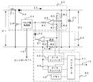
図2は、充電回路11の詳細回路である。
リアクトル21、ダイオード22,スイッチング素子23,パルス幅制御部24,差動増幅器25、抵抗R1,R2,R5,R6,R7でブースト・スイッチングレギュレータ回路20を構成し、蓄電器10の充電電圧を抵抗R1,R2で分圧した分圧電圧と、後述するD/Aコンバータ44から出力されるある電圧と抵抗R5,R7で決まる電圧との差を差動増幅器25で増幅してパルス幅制御部24に出力する。パルス幅制御部24は、インタフェース部18を介してコントローラ7に接続されており、コントローラ7からの信号により作動可能に制御される。
【0016】
コントローラ7は、モータ駆動装置に電源が投入されたとき、及び回生動作が終了したとき信号を出力してパルス幅制御部24を作動可能にする。このコントローラ7からの信号によりパルス幅制御部24が作動可能におかれている状態では、パルス幅制御部24は制御されたパルス幅の信号を出力しスイッチング素子23をオン/オフ制御する。スイッチング素子23がオンのときには、リアクトル21にエネルギーが蓄積され、スイッチング素子23がオフになると該エネルギーが放出され蓄電器10を充電する。そして、抵抗R1,R2,R6、差動増幅器25、パルス幅制御部24のフィードバック回路によって、充電回路11の出力すなわち蓄電器10の充電電圧は一定に制御されることになる。
【0017】
この充電回路11の入力電圧(DCリンク電圧)をVi、スイッチング素子23のオン時間をTon、オフ時間をToffとすると、充電回路11の出力電圧、すなわち蓄電器の充電電圧Voは、次の1式のようになる。
【0018】
Vo=Vi×(Ton+Toff)/Toff …(1)
例えば、Ton=5μs,Toff=15μsの時には、出力電圧Voは入力電圧Viの約1.3倍にブーストされることになる。このように、蓄電器10は、コンバータ部1で直流に変換されたDCリンク電圧より高い電圧で充電されることになる。
【0019】
蓄電器10の充電電圧が上昇している時には、抵抗R1,R2で分圧された分圧電圧も上昇し、差動増幅器25の出力電圧は低下する。その結果、パルス幅制御部24から出力されるオン時間Tonが短くなり、充電電圧の上昇は低下する。逆に蓄電器10の充電電圧の下降時には、差動増幅器25の出力電圧は上昇し、パルス幅制御部24から出力されるオン時間Tonが長くなり、充電電圧の下降を減少され、最終的に所定電圧を保持するように作用する。
【0020】
しかし、この蓄電器10への充電開始時、蓄電器10に大きな突入電流が流れ、コンバータ(整流回路)部1が破壊されないように充電回路11にはさらに、電流制限回路30が設けられている。この電流制限回路30は、差動増幅器31、ダイオード32,抵抗R0,R3,R4で構成されている。
【0021】
後述するD/Aコンバータ43からある電圧(例えばVとする)が出力され、この電圧Vが抵抗R4,R3で分圧され、その電圧V×R3/(R3+R4)が差動増幅器31に入力される。一方、この差動増幅器31の他方の端子には、蓄電器10への充電電流Icによる抵抗R0の電圧降下分の電圧が入力されており、この充電電流による電圧降下分の電圧が分圧電圧V×R3/(R3+R4)を越すと、差動増幅器31の出力は低下する。
【0022】
前述したように、ブースト・スイッチングレギュレータ回路20の出力電圧のフィードバック回路は、出力電圧(蓄電器10の充電電圧)の上昇時には、差動増幅器25の出力を低下させ、パルス幅制御部24から出力されるオン時間Tonのパルス幅を狭めて、出力電圧を低下させるように作用するものであるから、差動増幅器31の出力が低下すると、ダイオード32を介してパルス幅制御部24に入力される電圧が低下し、オン時間Tonのパルス幅を狭め、出力電圧を低下させ、充電電流Icによる抵抗R0での電圧降下を一定にするように作用する。これによって、蓄電器10への充電開始時における突入電流を制限し、所定上限値に制御する。
【0023】
一方、この充電電流Ic及び充電電圧の最大許容値は、モータ駆動装置のコンバータ(整流回路)部1の容量によって決まり、モータ制御装置の種類によって異なる。そこで、本実施形態では、モータ制御装置の種類によって、そのモータ駆動装置のコンバータ(整流回路)部1が許容できる電流値以下の充電電流Icに制限し、充電電圧を所定上限値以下に保持するための充電電流/電圧調整手段40を備えている。
【0024】
充電電流/電圧調整手段40は、コントローラ41、メモリ42、D/Aコンバータ43,44を備えている。メモリ42には、モータ駆動装置の種類に応じて許容電流値及び最大充電電圧値の情報が記憶されている。
【0025】
モータ駆動装置が変わったときなど、該モータ駆動装置を制御する数値制御装置等の制御装置9は、モータ駆動装置内のメモリ8に記憶するそのモータ駆動装置の仕様(モータ駆動装置を特定する情報)を、コントローラ7を介して読み込み、インタフェース17を介して、充電電流/電圧調整手段40内のコントローラ41に送りこむ。コントローラ41は送り込まれてきたモータ駆動装置の仕様に基づいて、メモリ42から許容電流値情報、最大充電電圧値情報を読み込み、許容電流値情報はD/Aコンバータ43に、最大充電電圧値情報はD/Aコンバータ44に送り、D/Aコンバータ43は、この許容電流値情報に基づく電圧を出力し、この電圧の抵抗R3,R4で分圧された電圧を差動増幅器31に入力する。また、D/Aコンバータ44から最大充電電圧値情報に基づく電圧を出力し抵抗R5とR7によって決まる電圧を差動増幅器25に入力する。
これによって、前述したように、モータ駆動装置のコンバータ(整流回路)部1が許容できる電流値以下、電圧値以下になるように充電電流、充電電圧が自動的に制限されることになる。
なお、上述した実施形態では、上位の制御装置9がメモリ8に記憶されている仕様データを読み出し、コントローラ41に出力するようにしているが、この上位の制御装置9を介さずに、モータ駆動装置に設けられているコントローラ7がメモリ8から仕様を読み込み、充電回路のコントローラ41に直接送信するようにしてもよい。
【0026】
【発明の効果】
本発明は、モータの減速時には回生電流を蓄え、加速時には放電する蓄電器に対する特別な整流回路等を設けることなく、モータ駆動装置のコンバータ部を利用するので、安価に構成することができる。しかも、モータ駆動装置のコンバータ部の整流能力に応じて、蓄電器への充電電流値の最大値を最適値にするものであるから、各種モータ駆動装置に適用でき、かつ既存のモータ駆動装置にも適用できるものである。
【図面の簡単な説明】
【図1】本発明の一実施形態であるモータ駆動装置のブロック回路図である。
【図2】同実施形態における蓄電器、充電回路の詳細ブロック回路図である。
【符号の説明】
1 コンバータ部
2 インバータ部
3 DCリンク部
4 蓄電部
5 モータ
10 蓄電器
11 充電回路
12 放電回路
20 ブースト・スイッチングレギュレータ回路
30 電流制限回路
40 充電電流/電圧調整手段[0001]
BACKGROUND OF THE INVENTION
The present invention relates to a motor drive device, and more particularly to a motor drive device that accumulates regenerative power and discharges the motor during acceleration to generate a motor drive current.
[0002]
[Prior art]
In the motor drive device, a large drive current flows for acceleration during the motor acceleration (powering) period, and a regenerative current is generated during the deceleration period. Therefore, the motor drive device must be designed in consideration of the peak current during the motor acceleration (powering) period, which leads to an increase in size and cost of the device. Further, the regenerative current generated during the deceleration period is dissipated and dissipated by the regenerative resistor, resulting in useless energy loss.
[0003]
As one countermeasure for solving such a problem, a converter (rectifier circuit) unit that converts AC power into DC power, an inverter unit that converts DC power into AC power to drive an AC motor, A capacitor is connected to a DC link unit connecting the converter (rectifier circuit) unit and the inverter unit, and the electric power stored in the capacitor is supplied to the inverter unit during the acceleration period, and the regenerative current is stored in the capacitor during the deceleration period. Thus, there is known an invention in which the drive current is leveled and the regenerative current is not wasted (see Patent Document 1).
[0004]
[Patent Document 1]
JP 2000-141440 A
[Problems to be solved by the invention]
As described in
[0006]
SUMMARY OF THE INVENTION Accordingly, an object of the present invention is to solve the above-described problems, and to store a regenerative current without being limited by the type of motor driving device, and to provide a motor including a power storage unit that supplies the stored power to an inverter unit during acceleration. It is to provide a driving device.
[0007]
[Means for Solving the Problems]
The present invention includes a converter unit that rectifies an AC power source and converts the AC power source into a DC power source, an inverter unit that converts the converted DC power source into an AC power source, a DC link unit that connects the converter unit and the inverter unit, and the DC link A motor drive device for driving an AC motor connected to the inverter unit, wherein the motor unit is connected to the inverter unit, stores a regenerative electric power during the motor decelerating drive, and discharges the electric power charged during the motor acceleration drive. The power storage unit includes an interface unit with a controller of the host control device or the motor drive device, and the upper limit value of the charging current / voltage can be changed based on data input from the interface unit. It is characterized by.
[0008]
The motor drive device includes a memory storing its own specifications and is connected to the host control device, and the controller of the motor control device or the controller of the motor drive device reads out the specifications of the motor drive device from the memory. The power storage unit changes the upper limit value of the charging current based on the input data.
The power storage unit includes a power storage unit, a charging circuit that charges the power storage unit with a voltage of a DC link unit, a diode that charges regenerative power during the deceleration drive of the motor to the capacitor, and the motor drive during acceleration driving of the motor. A discharge circuit for discharging the electric power charged in the battery. The charging circuit further includes a boost switching regulator that boosts the voltage of the DC link unit to charge the capacitor to the upper limit charging voltage, a current limiting circuit that limits a charging current to the upper limit, and a charging current. Charging voltage / voltage adjusting means for instructing the boost switching regulator and the current limiting circuit to specify a charging voltage upper limit value and a charging current lower limit value based on data inputted from the interface unit. It was supposed to be.
[0009]
DETAILED DESCRIPTION OF THE INVENTION
FIG. 1 is a block circuit diagram of a motor driving apparatus according to an embodiment of the present invention. In FIG. 1,
[0010]
The controller 7 is a controller in the motor drive device that performs on / off control of the switching element of the
[0011]
[0012]
Furthermore, in the present invention, the
[0013]
The charging circuit 11 controls the
[0014]
When starting the acceleration of the
In addition, the diode 13 is for storing a regenerative current generated when the
[0015]
FIG. 2 is a detailed circuit of the charging circuit 11.
Reactor 21,
[0016]
The controller 7 outputs a signal when the power is turned on to the motor driving device and when the regenerative operation is finished, thereby enabling the pulse
[0017]
When the input voltage (DC link voltage) of the charging circuit 11 is Vi, the on time of the switching
[0018]
Vo = Vi × (Ton + Toff) / Toff (1)
For example, when Ton = 5 μs and Toff = 15 μs, the output voltage Vo is boosted to about 1.3 times the input voltage Vi. Thus, the
[0019]
When the charging voltage of the
[0020]
However, the charging circuit 11 is further provided with a current limiting
[0021]
A voltage (for example, V) is output from a D /
[0022]
As described above, the feedback circuit of the output voltage of the boost switching
[0023]
On the other hand, the maximum allowable values of the charging current Ic and the charging voltage are determined by the capacity of the converter (rectifier circuit)
[0024]
The charging current / voltage adjusting means 40 includes a controller 41, a memory 42 , and D /
[0025]
When the motor driving device is changed, the control device 9 such as a numerical control device for controlling the motor driving device, the specification of the motor driving device stored in the
As a result, as described above, the charging current and the charging voltage are automatically restricted so that the converter (rectifier circuit)
In the above-described embodiment, the upper control device 9 reads the specification data stored in the
[0026]
【The invention's effect】
The present invention uses the converter section of the motor drive device without providing a special rectifier circuit or the like for storing a regenerative current when the motor is decelerated and discharges when the motor is accelerated, and thus can be configured at low cost. In addition, since the maximum value of the charging current to the battery is optimized according to the rectification capability of the converter unit of the motor drive device, it can be applied to various motor drive devices and can be applied to existing motor drive devices. Applicable.
[Brief description of the drawings]
FIG. 1 is a block circuit diagram of a motor driving apparatus according to an embodiment of the present invention.
FIG. 2 is a detailed block circuit diagram of a battery and a charging circuit in the same embodiment.
[Explanation of symbols]
DESCRIPTION OF
Claims (5)
Priority Applications (5)
| Application Number | Priority Date | Filing Date | Title |
|---|---|---|---|
| JP2003162549A JP3722810B2 (en) | 2003-06-06 | 2003-06-06 | Motor drive device |
| US10/859,237 US7227323B2 (en) | 2003-06-06 | 2004-06-03 | Motor driving apparatus |
| CNB2004100462539A CN1300932C (en) | 2003-06-06 | 2004-06-04 | Motor driving apparatus |
| EP04253318A EP1484832B1 (en) | 2003-06-06 | 2004-06-04 | Motor driving apparatus |
| DE602004029421T DE602004029421D1 (en) | 2003-06-06 | 2004-06-04 | Device for engine control |
Applications Claiming Priority (1)
| Application Number | Priority Date | Filing Date | Title |
|---|---|---|---|
| JP2003162549A JP3722810B2 (en) | 2003-06-06 | 2003-06-06 | Motor drive device |
Publications (2)
| Publication Number | Publication Date |
|---|---|
| JP2004364457A JP2004364457A (en) | 2004-12-24 |
| JP3722810B2 true JP3722810B2 (en) | 2005-11-30 |
Family
ID=33157223
Family Applications (1)
| Application Number | Title | Priority Date | Filing Date |
|---|---|---|---|
| JP2003162549A Expired - Fee Related JP3722810B2 (en) | 2003-06-06 | 2003-06-06 | Motor drive device |
Country Status (5)
| Country | Link |
|---|---|
| US (1) | US7227323B2 (en) |
| EP (1) | EP1484832B1 (en) |
| JP (1) | JP3722810B2 (en) |
| CN (1) | CN1300932C (en) |
| DE (1) | DE602004029421D1 (en) |
Families Citing this family (40)
| Publication number | Priority date | Publication date | Assignee | Title |
|---|---|---|---|---|
| JP4081101B2 (en) * | 2005-03-28 | 2008-04-23 | 富士通株式会社 | Power supply apparatus and power supply method |
| FI117938B (en) * | 2005-10-07 | 2007-04-30 | Kone Corp | Lift system |
| JP4737093B2 (en) * | 2007-01-09 | 2011-07-27 | 株式会社デンソー | Control device for multiphase rotating electrical machine |
| JP4390843B2 (en) * | 2007-10-05 | 2009-12-24 | ファナック株式会社 | Motor drive device |
| JP4339916B2 (en) * | 2008-02-28 | 2009-10-07 | ファナック株式会社 | Motor drive device |
| JP4512145B2 (en) * | 2008-03-21 | 2010-07-28 | ファナック株式会社 | Motor control device |
| JP4756559B2 (en) * | 2008-03-28 | 2011-08-24 | 株式会社日本製鋼所 | Electric power supply device for electric injection molding machine and electric injection molding machine |
| CN101728999B (en) * | 2008-10-10 | 2012-05-30 | 鸿富锦精密工业(深圳)有限公司 | Motor driving device |
| WO2010114520A1 (en) * | 2009-03-31 | 2010-10-07 | Otis Elevator Company | Elevator regenerative drive including an air core inductor |
| FI122048B (en) * | 2009-06-01 | 2011-07-29 | Kone Corp | The transportation system |
| KR101690355B1 (en) * | 2009-09-14 | 2016-12-27 | 이에스에이비 아베 | Inverter with commutation circuit |
| FI123470B (en) | 2009-12-28 | 2013-05-31 | Sandvik Mining & Constr Oy | Mining vehicles and procedure for its energy supply |
| EP2519419B1 (en) | 2009-12-28 | 2019-12-18 | Sandvik Mining and Construction Oy | Mining vehicle and method for its energy supply |
| JP5086396B2 (en) * | 2010-07-06 | 2012-11-28 | 株式会社日本製鋼所 | Electric power supply method for electric injection molding machine |
| RU2460204C1 (en) * | 2011-04-21 | 2012-08-27 | Открытое Акционерное Общество "Агрегатное Конструкторское Бюро "Якорь" | Autonomous starter-generator power supply system |
| TWI568149B (en) * | 2012-07-12 | 2017-01-21 | 台達電子工業股份有限公司 | Power conversion apparatus and controlling method thereof |
| JP5559261B2 (en) | 2012-07-17 | 2014-07-23 | ファナック株式会社 | Motor drive device having power storage device |
| ES2811598T3 (en) * | 2012-10-10 | 2021-03-12 | Daikin Ind Ltd | Direct energy conversion device and method of controlling the direct energy conversion device |
| JP5994603B2 (en) * | 2012-11-27 | 2016-09-21 | ダイキン工業株式会社 | Control method for direct power converter |
| KR101251477B1 (en) * | 2012-12-13 | 2013-04-05 | 김영준 | Energy saving alternatives for electric motors including low-cost power factor correction |
| JP5602890B2 (en) | 2013-01-29 | 2014-10-08 | ファナック株式会社 | Motor control device having power storage device and resistance discharge device |
| KR101449513B1 (en) | 2013-06-14 | 2014-10-14 | 주식회사 아모텍 | Motor Driving Apparatus Having Power Return Function and Driving Method thereof |
| JP2015016933A (en) * | 2013-07-09 | 2015-01-29 | 東芝エレベータ株式会社 | Drive control device of elevator |
| EP3083466B1 (en) | 2013-12-18 | 2020-03-18 | Otis Elevator Company | Multilevel drive half dc bus power supplies |
| EP3083469A4 (en) * | 2013-12-18 | 2017-09-20 | Otis Elevator Company | Bus capacitor bank configuration for a regenerative drive |
| US10135353B2 (en) | 2014-01-31 | 2018-11-20 | Eaton Intelligent Power Limited | Unidirectional matrix converter with regeneration system |
| JP5800953B1 (en) | 2014-05-12 | 2015-10-28 | ファナック株式会社 | Control device for injection molding machine having abnormality detection unit of voltage detection unit |
| JP5826440B1 (en) * | 2014-06-19 | 2015-12-02 | 三菱電機株式会社 | AC motor drive system |
| JP5805353B1 (en) * | 2014-06-26 | 2015-11-04 | 三菱電機株式会社 | Positioning control device |
| JP5850990B1 (en) * | 2014-07-17 | 2016-02-03 | ファナック株式会社 | Control device for injection molding machine having power converter control unit |
| JP6772577B2 (en) * | 2016-06-22 | 2020-10-21 | ダイキン工業株式会社 | Charge / discharge circuit, charge / discharge circuit control method, and direct power converter |
| RU2681839C1 (en) * | 2016-12-16 | 2019-03-13 | Федеральное государственное унитарное предприятие "Государственный научно-исследовательский институт авиационных систем" (ФГУП "ГосНИИАС") | Independent electric supply system |
| RU177678U1 (en) * | 2017-08-04 | 2018-03-06 | Федеральное государственное унитарное предприятие "Государственный научно-исследовательский институт авиационных систем" (ФГУП "ГосНИИАС") | Autonomous power supply system with electric start of the power plant |
| CN109455605B (en) * | 2017-09-06 | 2020-05-01 | 上海三菱电梯有限公司 | Elevator energy-saving device |
| EP3640175B1 (en) | 2018-10-19 | 2023-01-04 | Otis Elevator Company | Decentralized power management in an elevator system |
| EP3733578A1 (en) | 2019-05-03 | 2020-11-04 | Otis Elevator Company | Regenerative drive |
| EP3790177B1 (en) * | 2019-09-09 | 2024-05-01 | Andreas Stihl AG & Co. KG | Electric processing device and method for operating same |
| DE102021201113A1 (en) * | 2021-02-05 | 2022-08-11 | Knorr-Bremse Systeme für Nutzfahrzeuge GmbH | Braking of an electrically powered vehicle |
| RU2758793C1 (en) * | 2021-03-29 | 2021-11-01 | Федеральное Государственное Бюджетное Образовательное Учреждение Высшего Образования «Новосибирский Государственный Технический Университет» | Adaptive starter-generator system |
| JP2023112504A (en) * | 2022-02-01 | 2023-08-14 | オムロン株式会社 | Power source circuit and motor device |
Family Cites Families (27)
| Publication number | Priority date | Publication date | Assignee | Title |
|---|---|---|---|---|
| JPH0318285A (en) | 1989-06-14 | 1991-01-25 | Mitsubishi Electric Corp | Inverter device |
| JPH06343203A (en) | 1993-06-01 | 1994-12-13 | Nissan Motor Co Ltd | Electric car battery charger |
| JP3327631B2 (en) | 1993-06-30 | 2002-09-24 | 株式会社日立製作所 | Electric vehicle on-board charger |
| JPH08251934A (en) | 1995-03-15 | 1996-09-27 | Matsushita Electric Works Ltd | Inverter |
| US6335870B1 (en) | 1998-07-16 | 2002-01-01 | Mitsubishi Denki Kabushiki Kaisha | Inverter apparatus having a separate controlling application program for performing specification dependent control |
| JP3708728B2 (en) | 1998-11-05 | 2005-10-19 | 日創電機株式会社 | Motor drive device for injection molding machine |
| JP2000236679A (en) | 1999-02-16 | 2000-08-29 | Fuji Electric Co Ltd | Control method of power converter for motor control |
| JP2001069611A (en) | 1999-08-27 | 2001-03-16 | Honda Motor Co Ltd | Battery controller for hybrid car |
| JP3300307B2 (en) | 1999-09-22 | 2002-07-08 | 本田技研工業株式会社 | Hybrid vehicle control device |
| JP2001187677A (en) * | 1999-12-28 | 2001-07-10 | Mitsubishi Electric Corp | Controller for elevator |
| JP2001226049A (en) * | 2000-02-15 | 2001-08-21 | Mitsubishi Electric Corp | Control device for elevator |
| JP4343381B2 (en) * | 2000-02-28 | 2009-10-14 | 三菱電機株式会社 | Elevator control device |
| JP2001240323A (en) * | 2000-02-28 | 2001-09-04 | Mitsubishi Electric Corp | Control device of elevator |
| JP2001240326A (en) * | 2000-02-28 | 2001-09-04 | Mitsubishi Electric Corp | Control device of elevator |
| JP2001240325A (en) * | 2000-02-28 | 2001-09-04 | Mitsubishi Electric Corp | Control device of elevator |
| JP4249364B2 (en) * | 2000-02-28 | 2009-04-02 | 三菱電機株式会社 | Elevator control device |
| JP4261010B2 (en) * | 2000-02-28 | 2009-04-30 | 三菱電機株式会社 | Elevator control device |
| JP4283963B2 (en) * | 2000-02-28 | 2009-06-24 | 三菱電機株式会社 | Elevator control device |
| JP4302847B2 (en) * | 2000-02-28 | 2009-07-29 | 三菱電機株式会社 | Elevator control device |
| JP4347982B2 (en) * | 2000-02-28 | 2009-10-21 | 三菱電機株式会社 | Elevator control device |
| JP3736268B2 (en) | 2000-03-21 | 2006-01-18 | 日産自動車株式会社 | Control device for hybrid vehicle |
| JP4338876B2 (en) | 2000-05-09 | 2009-10-07 | 三菱電機株式会社 | Electric motor drive device and compressor drive device |
| JP2002145543A (en) | 2000-11-09 | 2002-05-22 | Mitsubishi Electric Corp | Control device of elevator |
| US6827182B2 (en) * | 2001-10-17 | 2004-12-07 | Mitsubishi Denki Kabushiki Kaisha | Elevator controller |
| US6768284B2 (en) * | 2002-09-30 | 2004-07-27 | Eaton Corporation | Method and compensation modulator for dynamically controlling induction machine regenerating energy flow and direct current bus voltage for an adjustable frequency drive system |
| JP3722811B2 (en) * | 2003-06-06 | 2005-11-30 | ファナック株式会社 | Motor drive device |
| JP4056512B2 (en) * | 2004-09-28 | 2008-03-05 | ファナック株式会社 | Motor drive device |
-
2003
- 2003-06-06 JP JP2003162549A patent/JP3722810B2/en not_active Expired - Fee Related
-
2004
- 2004-06-03 US US10/859,237 patent/US7227323B2/en not_active Expired - Lifetime
- 2004-06-04 DE DE602004029421T patent/DE602004029421D1/en not_active Expired - Lifetime
- 2004-06-04 CN CNB2004100462539A patent/CN1300932C/en not_active Expired - Fee Related
- 2004-06-04 EP EP04253318A patent/EP1484832B1/en not_active Expired - Lifetime
Also Published As
| Publication number | Publication date |
|---|---|
| US20040245952A1 (en) | 2004-12-09 |
| CN1574604A (en) | 2005-02-02 |
| DE602004029421D1 (en) | 2010-11-18 |
| EP1484832A3 (en) | 2006-09-27 |
| EP1484832B1 (en) | 2010-10-06 |
| CN1300932C (en) | 2007-02-14 |
| US7227323B2 (en) | 2007-06-05 |
| EP1484832A2 (en) | 2004-12-08 |
| JP2004364457A (en) | 2004-12-24 |
Similar Documents
| Publication | Publication Date | Title |
|---|---|---|
| JP3722810B2 (en) | Motor drive device | |
| EP1484831B1 (en) | Motor driving apparatus | |
| JP4056512B2 (en) | Motor drive device | |
| JP5167705B2 (en) | Switching power supply | |
| JP4775016B2 (en) | Switching power supply control circuit | |
| US20050151503A1 (en) | Converter and inverter including converter circuit | |
| US5949223A (en) | Power source apparatus having first and second switching power source units | |
| JP4321467B2 (en) | Power switching device | |
| JP6426775B2 (en) | Motor drive | |
| JP2007109609A (en) | Charging and discharging device of fuel cell system | |
| US4843300A (en) | Improved power supply for intermittently energizing an external device requiring high power during intermittent periods of time from an input power source with relatively lower instantaneous power capability | |
| US8487596B2 (en) | Driving circuitry and an integrated circuit for use therein | |
| US6115268A (en) | Method and apparatus for supplying uninterrupted power | |
| JP5844432B1 (en) | Power circuit | |
| JP5173124B2 (en) | Elevator control device | |
| KR102422113B1 (en) | Bidirectional DC-DC converter with improved auxiliary power | |
| JP6774891B2 (en) | Power supply | |
| JP6682930B2 (en) | Power supply | |
| JP4144220B2 (en) | Power converter | |
| JP2609646B2 (en) | Switching power supply | |
| JP2015211615A (en) | Power supply device and image forming apparatus | |
| JP2600315B2 (en) | Converter device | |
| JP4937958B2 (en) | Switching power supply | |
| JPH10271813A (en) | Stabilized power supply circuit | |
| JPS6122792A (en) | Control circuit of ac motor |
Legal Events
| Date | Code | Title | Description |
|---|---|---|---|
| A977 | Report on retrieval |
Free format text: JAPANESE INTERMEDIATE CODE: A971007 Effective date: 20050607 |
|
| A131 | Notification of reasons for refusal |
Free format text: JAPANESE INTERMEDIATE CODE: A131 Effective date: 20050614 |
|
| A521 | Request for written amendment filed |
Free format text: JAPANESE INTERMEDIATE CODE: A523 Effective date: 20050810 |
|
| TRDD | Decision of grant or rejection written | ||
| A01 | Written decision to grant a patent or to grant a registration (utility model) |
Free format text: JAPANESE INTERMEDIATE CODE: A01 Effective date: 20050830 |
|
| A61 | First payment of annual fees (during grant procedure) |
Free format text: JAPANESE INTERMEDIATE CODE: A61 Effective date: 20050913 |
|
| R150 | Certificate of patent or registration of utility model |
Ref document number: 3722810 Country of ref document: JP Free format text: JAPANESE INTERMEDIATE CODE: R150 Free format text: JAPANESE INTERMEDIATE CODE: R150 |
|
| FPAY | Renewal fee payment (event date is renewal date of database) |
Free format text: PAYMENT UNTIL: 20080922 Year of fee payment: 3 |
|
| FPAY | Renewal fee payment (event date is renewal date of database) |
Free format text: PAYMENT UNTIL: 20090922 Year of fee payment: 4 |
|
| FPAY | Renewal fee payment (event date is renewal date of database) |
Free format text: PAYMENT UNTIL: 20090922 Year of fee payment: 4 |
|
| FPAY | Renewal fee payment (event date is renewal date of database) |
Free format text: PAYMENT UNTIL: 20100922 Year of fee payment: 5 |
|
| FPAY | Renewal fee payment (event date is renewal date of database) |
Free format text: PAYMENT UNTIL: 20110922 Year of fee payment: 6 |
|
| FPAY | Renewal fee payment (event date is renewal date of database) |
Free format text: PAYMENT UNTIL: 20110922 Year of fee payment: 6 |
|
| FPAY | Renewal fee payment (event date is renewal date of database) |
Free format text: PAYMENT UNTIL: 20120922 Year of fee payment: 7 |
|
| FPAY | Renewal fee payment (event date is renewal date of database) |
Free format text: PAYMENT UNTIL: 20120922 Year of fee payment: 7 |
|
| FPAY | Renewal fee payment (event date is renewal date of database) |
Free format text: PAYMENT UNTIL: 20130922 Year of fee payment: 8 |
|
| LAPS | Cancellation because of no payment of annual fees |