JP3721834B2 - Negative pressure control device for brake booster - Google Patents
Negative pressure control device for brake booster Download PDFInfo
- Publication number
- JP3721834B2 JP3721834B2 JP06736199A JP6736199A JP3721834B2 JP 3721834 B2 JP3721834 B2 JP 3721834B2 JP 06736199 A JP06736199 A JP 06736199A JP 6736199 A JP6736199 A JP 6736199A JP 3721834 B2 JP3721834 B2 JP 3721834B2
- Authority
- JP
- Japan
- Prior art keywords
- negative pressure
- brake
- booster
- pedal
- pressure control
- Prior art date
- Legal status (The legal status is an assumption and is not a legal conclusion. Google has not performed a legal analysis and makes no representation as to the accuracy of the status listed.)
- Expired - Fee Related
Links
Images


Classifications
-
- B—PERFORMING OPERATIONS; TRANSPORTING
- B60—VEHICLES IN GENERAL
- B60T—VEHICLE BRAKE CONTROL SYSTEMS OR PARTS THEREOF; BRAKE CONTROL SYSTEMS OR PARTS THEREOF, IN GENERAL; ARRANGEMENT OF BRAKING ELEMENTS ON VEHICLES IN GENERAL; PORTABLE DEVICES FOR PREVENTING UNWANTED MOVEMENT OF VEHICLES; VEHICLE MODIFICATIONS TO FACILITATE COOLING OF BRAKES
- B60T8/00—Arrangements for adjusting wheel-braking force to meet varying vehicular or ground-surface conditions, e.g. limiting or varying distribution of braking force
- B60T8/32—Arrangements for adjusting wheel-braking force to meet varying vehicular or ground-surface conditions, e.g. limiting or varying distribution of braking force responsive to a speed condition, e.g. acceleration or deceleration
- B60T8/34—Arrangements for adjusting wheel-braking force to meet varying vehicular or ground-surface conditions, e.g. limiting or varying distribution of braking force responsive to a speed condition, e.g. acceleration or deceleration having a fluid pressure regulator responsive to a speed condition
- B60T8/42—Arrangements for adjusting wheel-braking force to meet varying vehicular or ground-surface conditions, e.g. limiting or varying distribution of braking force responsive to a speed condition, e.g. acceleration or deceleration having a fluid pressure regulator responsive to a speed condition having expanding chambers for controlling pressure, i.e. closed systems
- B60T8/4275—Pump-back systems
- B60T8/4291—Pump-back systems having means to reduce or eliminate pedal kick-back
-
- B—PERFORMING OPERATIONS; TRANSPORTING
- B60—VEHICLES IN GENERAL
- B60T—VEHICLE BRAKE CONTROL SYSTEMS OR PARTS THEREOF; BRAKE CONTROL SYSTEMS OR PARTS THEREOF, IN GENERAL; ARRANGEMENT OF BRAKING ELEMENTS ON VEHICLES IN GENERAL; PORTABLE DEVICES FOR PREVENTING UNWANTED MOVEMENT OF VEHICLES; VEHICLE MODIFICATIONS TO FACILITATE COOLING OF BRAKES
- B60T13/00—Transmitting braking action from initiating means to ultimate brake actuator with power assistance or drive; Brake systems incorporating such transmitting means, e.g. air-pressure brake systems
- B60T13/10—Transmitting braking action from initiating means to ultimate brake actuator with power assistance or drive; Brake systems incorporating such transmitting means, e.g. air-pressure brake systems with fluid assistance, drive, or release
- B60T13/66—Electrical control in fluid-pressure brake systems
- B60T13/662—Electrical control in fluid-pressure brake systems characterised by specified functions of the control system components
-
- B—PERFORMING OPERATIONS; TRANSPORTING
- B60—VEHICLES IN GENERAL
- B60T—VEHICLE BRAKE CONTROL SYSTEMS OR PARTS THEREOF; BRAKE CONTROL SYSTEMS OR PARTS THEREOF, IN GENERAL; ARRANGEMENT OF BRAKING ELEMENTS ON VEHICLES IN GENERAL; PORTABLE DEVICES FOR PREVENTING UNWANTED MOVEMENT OF VEHICLES; VEHICLE MODIFICATIONS TO FACILITATE COOLING OF BRAKES
- B60T13/00—Transmitting braking action from initiating means to ultimate brake actuator with power assistance or drive; Brake systems incorporating such transmitting means, e.g. air-pressure brake systems
- B60T13/10—Transmitting braking action from initiating means to ultimate brake actuator with power assistance or drive; Brake systems incorporating such transmitting means, e.g. air-pressure brake systems with fluid assistance, drive, or release
- B60T13/66—Electrical control in fluid-pressure brake systems
- B60T13/68—Electrical control in fluid-pressure brake systems by electrically-controlled valves
- B60T13/683—Electrical control in fluid-pressure brake systems by electrically-controlled valves in pneumatic systems or parts thereof
Landscapes
- Engineering & Computer Science (AREA)
- Transportation (AREA)
- Mechanical Engineering (AREA)
- Physics & Mathematics (AREA)
- Fluid Mechanics (AREA)
- Valves And Accessory Devices For Braking Systems (AREA)
- Braking Systems And Boosters (AREA)
- Regulating Braking Force (AREA)
- Electrical Control Of Air Or Fuel Supplied To Internal-Combustion Engine (AREA)
- Control Of Vehicle Engines Or Engines For Specific Uses (AREA)
Description
【0001】
【発明の属する技術分野】
本発明は、ブレーキブースタ用負圧制御装置に関し、特に、エンジンの吸気管負圧を用いてブレーキ操作を助勢するブレーキブースタの負圧制御に好適な負圧制御装置に関する。
【0002】
【従来の技術】
従来より、例えば特開平10−167047号公報に開示される如く、ブレーキブースタの負圧を制御する負圧制御装置が公知である。ブレーキブースタは、エンジンのスロットル弁より下流側の吸気管の負圧(以下、吸気管負圧と称す)を用いてブレーキペダルの踏み込みを助勢し、大きな制動力を発生させる。上記従来の負圧制御装置は、燃焼室内に燃料噴射弁を備え、燃料を燃焼室に直接噴射する直接噴射式エンジン (以下、直噴式エンジンと称す)に適用されている。直噴式エンジンによれば、例えば低負荷運転時等において、スロットル弁を開弁して多量の空気を燃焼室に供給することにより、成層燃焼による燃費の向上を図ることができる。従って、直噴式エンジンにおいては、アクセル操作が行われていなくとも、スロットル弁が開弁されることで吸気管負圧が低下し、ブレーキブースタに十分な負圧が供給されなくなる場合がある。このため、上記従来の負圧制御装置では、ブレーキブースタの負圧が基準値を下回ると、スロットル開度を減少させて大きな吸気管負圧を発生させることとしている。
【0003】
しかしながら、スロットル開度を減少させた場合には、エンジン出力の低下によるトルク変化を招くと共に、エンジンの燃焼状態がストイキ燃焼へ切り替わることによる燃費の悪化を招く。そこで、上記従来の負圧制御装置では、上記基準値を車速に応じて変更することにより、トルク変化や燃費の悪化を抑制しつつ負圧を確保することとしている。
【0004】
【発明が解決しようとする課題】
ところで、アンチロックブレーキ制御(ABS制御)の実行中は、ブレーキ液圧の増減が繰り返されるのに伴ってブレーキペダルが振動する。一方、ブレーキブースタの負圧は、ブレーキペダルのストロークが変化する際に消費される。このため、ブレーキペダルが振動すると、ブレーキブースタの負圧消費量は大きくなる。すなわち、ABS制御の実行中は、通常時に比べてブレーキブースタの負圧は大きな度合いで消費される。しかしながら、上記従来の装置では、ABS制御の実行の有無は考慮されておらず、ABS制御中にブレーキブースタの負圧が不足する可能性がある。
【0005】
本発明は、上述の点に鑑みてなされたものであり、ブレーキペダルの振動に起因してブレーキブースタの負圧の消費量が大きい場合にも、ブレーキブースタの負圧が不足するのを防止し得るブレーキブースタ用負圧制御装置を提供することを目的とする。
【0006】
【課題を解決するための手段】
上記の目的は、請求項1に記載する如く、負圧を用いてブレーキペダルの踏み込みを助勢するブレーキブースタの負圧を制御するブレーキブースタ用負圧制御装置であって、
前記ブレーキペダルの振動状態を判定するペダル振動状態判定手段と、
ブレーキ液圧の増減が繰り返されるのに伴うブレーキペダルの振動状態が検出された場合に、前記ブレーキブースタの負圧が大きくなるように前記ブレーキブースタの負圧を制御する負圧制御手段と、を備えるブレーキブースタ用負圧制御装置により達成される。
【0007】
請求項1記載の発明において、ブレーキブースタの負圧は、ブレーキペダルのストロークが増加し、又は減少する毎に消費される。従って、ブレーキペダルが振動すると、負圧が繰り返し消費されることで、負圧の消費量は大きくなる。本発明によれば、負圧制御手段がブレーキペダルの振動状態に応じてブレーキブースタを制御する。このため、ブレーキペダルが振動している場合に、ブレーキブースタの負圧が不足するのを防止できる。
【0008】
この場合、請求項2に記載する如く、請求項1記載のブレーキブースタ用負圧制御装置において、
アンチロックブレーキ制御を実行し得る車両に搭載され、
前記ペダル振動状態判定手段は、アンチロックブレーキ制御の実行中であるか否かに基づいてブレーキペダルの振動状態を判定することとしてもよい。
【0009】
請求項2記載の発明において、アンチロックブレーキ制御の実行中は、ブレーキ液圧の増減が繰り返されるのに伴ってブレーキペダルが振動する。従って、本発明によれば、アンチロックブレーキ制御の実行中にブレーキブースタの負圧が不足するのを防止できる。
また、請求項1記載の発明において、請求項3記載に記載する如く、前記ペダル振動状態判定手段は、前記ブレーキペダルの振動を検出するブレーキ振動検出手段を備え、
前記負圧制御手段は、前記ブレーキ振動検出手段により検出されたブレーキ振動の大きさが所定値を超える場合に、前記ブレーキブースタの負圧制御を行うこととしてもよい。この場合、請求項4記載に記載する如く、前記負圧制御手段は、前記ブレーキ振動検出手段により検出されたブレーキ振動の大きさが大きいほど前記ブレーキブースタの負圧が大きくなるように、前記ブレーキブースタの負圧制御を行うこととしてもよい。
【0010】
【発明の実施の形態】
図1は、本発明の一実施例であるシステムの全体構成図を示す。本実施例のシステムはエンジン10を備えている。エンジン10はエンジンECU12により制御される。エンジン10は、シリンダブロック13を備えている。シリンダブロック13の内部には、シリンダ14が形成されている。エンジン10は、複数のシリンダを備えている。図1は、複数のシリンダのうち一のシリンダ14を表す。
【0011】
シリンダ14の内部にはピストン16が配設されている。ピストン16は、シリンダ14の内部を、図1における上下方向に摺動することができる。シリンダ14の内部のピストン16より上方には燃焼室18が画成されている。燃焼室18には燃料噴射弁20の噴射口が露出している。燃料噴射弁20はエンジンECU12に接続されている。燃料噴射弁20はエンジンECU12から供給される制御信号に応じて燃焼室18内へ燃料を噴射する。すなわち、本実施例のエンジン10は直噴式エンジンとして構成されている。
【0012】
燃焼室18には、排気弁22を介して排気管24が連通している。燃焼室18には、また、吸気弁26を介して吸気マニホールド28の各枝管が連通している。吸気マニホールド28はその上流側においてサージタンク30に連通している。サージタンク30の更に上流側には吸気管32が連通している。
吸気管32にはスロットル弁34が配設されている。スロットル弁34はスロットルモータ36に連結されている。スロットルモータ36はエンジンECU12に電気的に接続されている。スロットルモータ36はエンジンECU12から供給される制御信号に応じてスロットル弁34の開度を変化させる。
【0013】
スロットル弁34の近傍には、スロットル開度センサ38が配設されている。スロットル開度センサ38はスロットル弁34の開度(以下、スロットル開度SCと称す)に応じた電気信号をエンジンECU12に向けて出力する。エンジンECU12はスロットル開度センサ38の出力信号に基づいてスロットル開度SCを検出する。
【0014】
吸気管32のスロットル弁34より下流側の部位(以下、下流側吸気通路32aと称す)には、吸気圧センサ40が配設されている。吸気圧センサ40は下流側吸気通路32aの負圧(以下、吸気管負圧PMと称す)に応じた電気信号をエンジンECU12に向けて出力する。エンジンECU12は吸気圧センサ40の出力信号に基づいて吸気管負圧PMを検出する。
【0015】
下流側吸気通路32aには、負圧供給通路42の一端が接続されている。負圧供給通路42の他端は、ブレーキブースタ44に接続されている。
ブレーキブースタ44はその内部にダイヤフラム44aを備えている。ダイヤフラム44aは、ブレーキブースタ44の内部空間を図1中左側の負圧室44bと右側の変圧室44cとに区画している。上記した負圧供給通路42は負圧室44bに接続されている。ブレーキブースタ44は、また、負圧サーボ機構44dを備えている。負圧サーボ機構44dには、オペレーティングロッド45を介してブレーキペダル46が連結されている。また、ダイヤフラム44aには、マスタシリンダ48のプッシュロッド48aが連結されている。
【0016】
負圧供給通路42にはチェックバルブ50が配設されている。チェックバルブ46はブレーキブースタ44側から吸気管32側への空気の流れのみを許容する一方向弁である。従って、吸気管負圧PMが負圧室44bの負圧(以下、ブースタ負圧PBと称す)よりも大きい場合には、吸気管負圧PMが負圧室44bに供給され、一方、吸気管負圧PMがブースタ負圧PBよりも小さい場合には、ブースタ負圧PBが吸気管32側へ逃げることが防止される。なお、本明細書において、「負圧」は大気圧との圧力差で表されるものとする。従って、「負圧が大きい」とは、大気圧との圧力差が大きいこと、すなわち、絶対的な圧力としては低圧であることを意味する。
【0017】
負圧室44bには、ブースタ圧センサ52が配設されている。ブースタ圧センサ52は、ブースタ負圧PBに応じた電気信号をエンジンECU12に向けて出力する。エンジンECU12はブースタ圧センサ52の出力信号に基づいてブースタ負圧PBを検出する。
ブレーキブースタ44が備えるサーボ機構44dは、ブレーキペダル46が踏み込まれていない場合には、変圧室44cを負圧室44bに連通させると共に大気から遮断し、ブレーキペダル46が踏み込まれると、変圧室44cを負圧室44bから遮断すると共に、ブレーキペダル46に付与される踏力(以下、ペダル踏力Fと称す)に応じて大気を変圧室44cに導入する。従って、負圧室44bと変圧室44cとの間にはペダル踏力Fに応じた差圧が発生する。かかる差圧に応じた力とペダル踏力Fとの合力がダイヤフラム44aを介してプッシュロッド48aに伝達される。従って、マスタシリンダ48に各液室には、ペダル踏力Fに対して所定の倍力比を有する液圧が発生する。以下、マスタシリンダ48の各液室に発生する液圧をマスタシリンダ圧PM/C と称す。このように、ブレーキブースタ44は、ブースタ負圧PBを用いてブレーキペダル46の踏み込みを助勢することにより、大きなマスタシリンダ圧PM/C を発生させる。
【0018】
マスタシリンダ48の各液室には、それぞれ配管54、56を介して、液圧ブレーキ装置58が連通している。液圧ブレーキ装置58はブレーキECU60により制御される。液圧ブレーキ装置58については後に詳述する。
ブレーキペダル46には踏力センサ62が装着されている。踏力センサ62は、ペダル踏力Fに応じた電気信号をブレーキECU60に向けて出力する。ブレーキECU60は踏力センサ62の出力信号に基づいてペダル踏力Fを検出する。また、ブレーキペダル46の近傍にはストロークセンサ64が配設されている。ブレーキスイッチ64は、ブレーキペダル46のストローク量(以下、ペダルストロークSTと称す)に応じた電気信号をブレーキECU60に向けて出力する。ブレーキECU60はストロークセンサ64の出力信号に基づいてペダルストロークSTを検出する。
【0019】
エンジン10には回転数センサ68が設けられている。回転数センサ68は、エンジン回転数Neに応じたパルス信号をエンジンECU12に向けて出力する。エンジンECU12は、回転数センサ68から供給されるパルス信号に基づいてエンジン回転数Neを検出する。
アクセルペダル70の近傍にはアクセル開度センサ72が配設されている。アクセル開度センサ72は、アクセルペダル70の踏み込み量(以下、アクセル開度ACと称す)に応じた電気信号をエンジンECU12に向けて出力する。エンジンECU12はアクセル開度センサ72から供給される信号に基づいてアクセル開度ACを検出する。
【0020】
次に、液圧ブレーキ装置58の構成及び動作について説明する。図2は液圧ブレーキ装置58の構成図である。図2に示す如く、液圧ブレーキ装置58は、配管56に接続されたフロントマスタ通路100、及び、配管54に接続されたリアマスタ通路102を備えている。リアマスタ通路102にはマスタ圧センサ103が配設されている。マスタ圧センサ103は、リアマスタ通路102の内部の液圧、すなわち、マスタシリンダ圧PM/C に応じた信号をブレーキECU60に向けて出力する。ブレーキECU60はマスタ圧センサ103の出力信号に基づいてマスタシリンダ圧PM/C を検出する。
【0021】
フロントマスタ通路100は、保持バルブ104,106を介して、それぞれ、ホイルシリンダ通路108,110に接続されている。ホイルシリンダ通路108,110は、それぞれ、右前輪FR及び左前輪FLのホイルシリンダ112,114に接続されている。保持バルブ104,106は、共に、常態で開弁状態をとり、ブレーキECU60からオン信号を供給されることにより閉弁状態となる常開の電磁開閉バルブである。保持バルブ104、106には、それぞれ、チェックバルブ116,118が並設されている。チェックバルブ116,118は、それぞれ、ホイルシリンダ通路108,110側から前輪側マスタ通路100側へ向かうフルードの流れのみを許容する一方向弁である。
【0022】
ホイルシリンダ通路108,110は、それぞれ、減圧バルブ120,122を介してリザーバ124に接続されている。減圧バルブ120,122は、共に、常態で閉弁状態をとり、ブレーキECU60からオン信号を供給されることにより開弁状態となる常閉の電磁開閉バルブである。リザーバ124には、ポンプ126の吸入側が連通している。また、ポンプ126の吐出側はフロントマスタ通路100に連通している。
【0023】
リアマスタ通路102は、保持バルブ128を介してホイルシリンダ通路130に接続されている。ホイルシリンダ通路130は右後輪RR及び左後輪RLのホイルシリンダ132,134の双方に連通している。保持バルブ128は、常態で開弁状態をとり、ブレーキECU60からオン信号を供給されることにより閉弁状態となる常開の電磁開閉バルブである。保持バルブ128にはチェックバルブ136が並設されている。チェックバルブ136はホイルシリンダ通路130側からリアマスタ通路102側へ向かうフルードの流れのみを許容する一方向弁である。
【0024】
ホイルシリンダ通路130には、減圧バルブ138を介してリザーバ140が接続されている。減圧バルブ138は常態で閉弁状態をとり、ブレーキECU60からオン信号を供給されることにより開弁状態となる電磁開閉バルブである。リザーバ140には、ポンプ142の吸入側が連通している。また、ポンプ142の吐出側はリアマスタ通路102に連通している。
【0025】
右前輪FR、左前輪FL、右後輪RR、及び左後輪RLの近傍には、それぞれ、車輪側センサ144,146,148,150が配設されている。車輪速センサ144〜150は各輪の車輪速VWに応じた電気信号をブレーキECU60に向けて出力する。ブレーキECU60は、車輪速センサ144〜150の出力信号に基づいて各輪の車輪速VWを検出し、各車輪速VWを用いて車速Vを求める。
【0026】
次に、液圧ブレーキ装置58の動作について説明する。液圧ブレーキ装置58は、ブレーキECU60が各電磁弁の状態を適宜切り替えることにより、マスタシリンダ圧PM/C に応じた制動力を発生する通常ブレーキ機能、及び、車輪のロックを防止するABS機能を実現することができる。
通常ブレーキ機能は、図2に示す如く、液圧ブレーキ装置58が備える全ての電磁弁をオフ状態とし、かつ、ポンプ126,142を停止させることにより実現される。以下、図2に示す状態を通常ブレーキ状態と称す。図2に示す通常ブレーキ状態において、前輪側のホイルシリンダ112,114は、ホイルシリンダ通路108,110及びフロントマスタ通路100を介してマスタシリンダ48に連通する。また、後輪側のホイルシリンダ132,134は、ホイルシリンダ通路130及びリアマスタ通路102を介してマスタシリンダ48に連通する。従って、通常ブレーキ状態では、ホイルシリンダ112,114,132,134の液圧(以下、ホイルシリンダ圧PW/C と称す)は、常にマスタシリンダ圧PM/C と等圧に制御される。
【0027】
ABS機能は、図2に示す通常ブレーキ状態において、ポンプ126,142を作動させ、かつ、保持バルブ104,106,128及び減圧バルブ120,122,138を各車輪のスリップ状態に応じて開閉駆動することにより実現される。以下、本実施例のシステムにおいてABS機能を実現するための制御をABS制御と称す。
【0028】
ブレーキECU60は、ブレーキペダル46が踏み込まれ、かつ、何れかの車輪について過剰なスリップ率が検出された場合にABS制御を開始する。ABS制御の実行中は、ブレーキペダル46の踏み込みに伴って昇圧されたマスタシリンダ圧PM/C が、フロントマスタ通路100及びリアマスタ通路102に導かれる。かかる状況下で保持バルブ104,106,128を開弁状態とし、かつ、減圧バルブ120,122,138を閉弁状態とすると、各車輪のホイルシリンダ圧PW/C をマスタシリンダ圧PM/C に向けて増圧することができる。以下、この状態を増圧モードと称す。
【0029】
また、ABS制御の実行中に、保持バルブ104,106,128及び減圧バルブ120,122,138を閉弁状態とすると、各車輪のホイルシリンダ圧PW/C を保持することができる。以下、この状態を保持モードと称す。
更に、ABS制御の実行中に、保持バルブ104,106,128を閉弁状態とし、かつ、減圧バルブ120,122,138を開弁状態とすると、各車輪のホイルシリンダ圧PW/C を減圧することができる。以下、この状態を減圧モードと称す。
【0030】
ECU12は、ABS制御中に、各車輪毎に適宜上記の増圧モード、保持モード、及び、減圧モードが実現されるように、各車輪のスリップ状態に応じて保持バルブ104,106.128及び減圧バルブ120,122,138を制御する。この場合、全ての車輪のホイルシリンダ圧PW/C が、対応する車輪に過大なスリップ率を発生させることのない適当な圧力に制御される。このように、上記の制御によれば、本実施例のシステムにおいてABS機能を実現することができる。
【0031】
ABS制御の実行中に各車輪で減圧モードが行われる際には、ホイルシリンダ112,114,132,134内のブレーキフルードがリザーバ124、140へ流入する。リザーバ124,140へ流入したブレーキフルードは、ポンプ126,142によって、それぞれ、フロントマスタ通路100及びリアマスタ通路102へ供給される。フロントマスタ通路100及びリアマスタ通路102へ供給されたブレーキフルードの一部は、各車輪で増圧モードが行われる際にホイルシリンダ112,114,132,134に流入する。また、そのブレーキフルードの残部は、ブレーキフルードの流出分を補うべくマスタシリンダ48に流入する。
【0032】
このように、ABS制御の実行中は、ブレーキペダル46の踏み込みに伴ってホイルシリンダ112,114,132,134に流入したブレーキフルードが、減圧モード時にリザーバ124,140に流出することにより、ペダルストロークSTは増加する。また、増圧モード時には、ポンプ126,142によりリザーバ124、142から汲み上げられたブレーキフルードの一部がマスタシリンダ48に戻されることにより、ペダルストロークSTは減少する。すなわち、ABS制御の実行中は、増圧モードと減圧モードとが繰り返されるのに伴って、ブレーキペダル46に振動が生ずることとなる。
【0033】
ところで、本実施例のシステムにおいて、エンジン10は、その負荷状態に応じて成層燃焼モード又はストイキ燃焼モードの何れかのモードで作動する。ストイキ燃焼モードは、アクセル開度ACに応じてスロットル開度SCを制御し、アクセル開度ACに応じた流量の空気を燃焼室18に供給することにより、燃焼室18内でストイキ燃焼を実現する動作モードである。一方、成層燃焼モードは、スロットル開度SCを大きくし、多量の空気を燃焼室18に供給すると共に、アクセル開度ACに応じた燃料を圧縮行程において噴射することにより、燃焼室18内で成層燃焼を実現する動作モードである。
【0034】
成層燃焼モードによれば、ストイキ燃焼よりも大きな空燃比で燃焼が行われることでエンジン10の燃費が向上する。更に、成層燃焼モードによれば、スロットル開度SCが大きくされることで、エンジン10のポンピングロスが低減されることによっても燃費が向上する。従って、エンジン10の燃費を向上させる観点から、エンジン10を可能な限り成層燃焼モードで作動させることが望ましい。しかしながら、エンジン10の負荷(すなわち、アクセル開度AC)が増大すると、燃料噴射弁20により噴射すべき燃料の量も大きくなる。この場合、燃料噴射量が一定値を越えると、スロットル開度SCを全開としても、吸気管32に吸入される空気量(以下、吸入空気量Qと称す)が燃料噴射量に対して不足し、成層燃焼を実現することができなくなる。
【0035】
そこで、エンジンECU12はアクセル開度ACに基づいて燃料噴射量を決定し、その燃料噴射量により成層燃焼が可能か否かを判定する。そして、成層燃焼が可能であると判定した場合には、スロットル開度SCを全開にすると共に、圧縮行程においてアクセル開度ACに応じた量の燃料を燃料噴射弁20によって噴射させることにより成層燃焼モードを実現する。一方、エンジンECU12は、成層燃焼は不可能であると判定した場合には、スロットル開度SCをアクセル開度ACに応じた値に制御すると共に、吸気行程においてスロットル開度SCに応じた量の燃料を燃料噴射弁20によって噴射させることにより、ストイキ燃焼モードを実現する。
【0036】
上述の如く、成層燃焼モードでは、アクセル開度ACにかかわらず、スロットル開度SCは全開にされる。スロットル開度SCが全開にされると、吸気管負圧PMは低下する。一方、上述の如く、ブレーキブースタ44は、ブースタ負圧PBを動力源としてブレーキペダル46の踏み込みを助勢する。ブレーキブースタ44による助勢が行われると、制動力が増加するにつれてブースタ負圧PBは消費される。このため、成層燃焼モードでは、下流側吸気通路32aからブレーキブースタ44の負圧室44bに十分な負圧を供給することができず、ブレーキ操作の実行に伴ってブースタ負圧PBは次第に低下する。従って、エンジン10が生成燃焼モードで作動している場合にブレーキ操作が行われると、ブースタ負圧PBが不足して、ブレーキブースタ44による十分な助勢を行うことができない事態が生じ得る。
【0037】
かかる事態は、スロットル開度SCを絞り、大きな吸気管負圧PMを生成することにより回避することができる。すなわち、大きな吸気管負圧PMが生成されれば、この負圧が負圧室44bに供給されることで、大きなブースタ負圧PBを確保することができる。以下、スロットル開度SCを絞ることにより大きブースタ負圧PBを生成するための制御を、ブースタ負圧制御と称す。
【0038】
しかしながら、上述の如く、成層燃焼モードにおいてスロットル開度SCが絞られると、ポンピングロスの増加により燃費が悪化すると共にエンジン出力が低下し、更に、成層燃焼モードが維持できなくなるまでスロットル開度SCが絞られると、エンジン10の動作モードがストイキ燃焼モードに切り替えられることにより、燃費の一層の悪化を招いてしまう。従って、良好な燃費を実現する等の観点から、ブースタ負圧制御による負圧の生成は必要最小限の範囲で行われることが望ましい。
【0039】
ところで、上述の如く、ABS制御の実行中は、ブレーキペダル46に振動が生じ、ペダルストロークSTは増減を繰り返す。ペダルストロークSTが増加すると、変圧室44cに大気が導入され、ブレーキブースタ44の負圧室44bと変圧室44cとの間の差圧が増加することで、ダイヤフラム44aが負圧室44b側へ撓む。この場合、負圧室44bの容積が減少することによりブースタ負圧PBが消費される。また、ペダルストロークSTが減少すると、その減少分に応じて負圧室44bから変圧室44cへ負圧が供給されることにより、ブースタ負圧PBが消費される。すなわち、ペダルストロークSTが変化する毎に、ブースタ負圧PBが消費される。このため、ABS制御の実行中は、ブレーキペダル46の振動に伴ってブースタ負圧PBが繰り返し消費されることとなり、ブースタ負圧PBの消費量は大きくなる。
【0040】
本実施例のシステムは、上記の点に鑑みて、ABS制御の実行中にブースタ負圧制御を実行することにより、ブースタ負圧PBが不足するのを防止するものである。
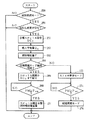
以下、図3及び図4を参照して、本実施例においてブレーキECU60及びエンジンECU12が実行する具体的な処理について説明する。まず、ブレーキECU60が実行する処理について説明する。図3は、ブレーキECU60が実行するルーチンのフローチャートである。図3に示すルーチンはその処理が終了する毎に繰り返し起動される。図3に示すルーチンが起動されると、先ずステップ200の処理が実行される。
【0041】
ステップ200では、車速Vが所定の基準値V1以上であるか否かが判別される。その結果、V≧V1が不成立であれば、車両停止までのブースタ負圧PBの消費量は小さく、ブースタ負圧制御を実行することは不要であると判断されて今回のルーチンは終了される。このように、ステップ200の処理によれば、車速Vが基準値V1未満の場合はブースタ負圧制御が実行されないため、低速走行時又はアイドル運転時における燃費の悪化が防止される。一方、ステップ200において、V≧V1が成立する場合は、次にステップ202の処理が実行される。
【0042】
ステップ202では、マスタ圧センサ103の出力値が有効であるか否かが判別される。かかる判別は、例えばマスタ圧センサ103がペダル踏力Fに応じた値を出力しているか否かを随時判定しておき、その判定結果に基づいて行うことができる。ステップ202において、マスタ圧センサ103の出力値が有効であれば、次にステップ204の処理が実行される。
【0043】
ステップ204では、マスタ圧センサ103の出力値に基づいて検出されたマスタシリンダ圧PM/C が所定の基準値α2 以上であるか否かが判別される。その結果、PM/C ≧α2 が成立する場合は、運転者は大きな制動力を要求しており、ブースタ負圧PBの消費量は大きいと判断される。この場合、ブースタ負圧制御を実行すべきと判断されて次にステップ206の処理が実行される。一方、ステップ204において、PM/C ≧α1が不成立であれば、次にステップ208の処理が実行される。
【0044】
ステップ208では、マスタシリンダ圧PM/C の増加勾配ΔPM/C (=dPM/C /dt)が所定の基準値α2 以上であるか否かが判別される。その結果、ΔPM/C ≧α2 が成立する場合は、運転者は制動力の速やかな立ち上がりを要求しており、ブースタ負圧PBの消費量は大きいと判断される。この場合、ブースタ負圧制御を実行すべきと判断されて次にステップ206の処理が実行される。一方、ステップ208において、PM/C ≧α2 が不成立であれば、次にステップ210の処理が実行される。
【0045】
なお、ステップ204,208において、マスタシリンダ圧PM/C 及びその増加勾配ΔPM/C に代えて、ペダルストロークST及びその増加勾配をそれぞれ基準値と比較することにより、ブースタ負圧制御の要否を判別してもよい。
一方、上記ステップ202においてマスタ圧センサ103の出力値が有効でなければ、ステップ204,208はスキップされて、次にステップ210の処理が実行される。従って、上記ステップ202の処理によれば、有効でないマスタ圧センサ103の出力値に基づいて、ブースタ負圧制御の要否が誤って判断されることが防止される。
【0046】
ステップ210では、踏力センサ62が正常であるか否かが判別される。かかる判別は、例えばイニシャルチェック時における踏力センサ62の異常判定結果に基づいて行われる。ステップ210において、踏力センサ62が正常である場合は、次にステップ212の処理が実行される。
ステップ212では、ペダル踏力Fが所定の基準値α3 以上であるか否かが判別される。その結果、F≧α3 が成立する場合は、運転者が大きな制動力を要求しており、ブースタ負圧PBの消費量が大きいと判断される。この場合、ブースタ負圧制御を実行すべきと判断されて次にステップ206の処理が実行される。一方、ステップ212においてF≧α3 が不成立であれば、次にステップ214の処理が実行される。
【0047】
なお、ステップ212では、ペダル踏力Fに代えて、又は、ペダル踏力Fに加えて、ペダル踏力Fの増加勾配(dF/dt)が所定の基準値を越える場合に、ブースタ負圧制御を実行すべきと判断することとしてもよい。また、踏力センサ62に代えて、ペダル踏力Fが所定値に達するとオン・オフ状態が切り替わる踏力スイッチを設け、この踏力スイッチのオン・オフ状態に基づいて、ブースタ負圧制御の要否を判断することとしてもよい。
【0048】
ところで、ブースタ負圧PBが極端に不足した場合には、ブレーキブースタPBによる助勢はほとんど行われない。この場合、運転者が大きな踏力でブレーキペダルを踏み込んでも、マスタシリンダ圧PM/C 及びペダルストロークSTの増加量は小さいため、マスタシリンダPM/C 又はペダルストロークSTによってはブースタ負圧制御の要否を適正に判断することはできない。これに対して、ステップ212では、ペダル踏力Fを用いることで、ブースタ負圧PBが極端に不足する場合にもブースタ負圧制御の要否を確実に判定することができる。
【0049】
一方、上記ステップ210において踏力センサ62が正常でなければ、ステップ212はスキップされて、次にステップ214の処理が実行される。従って、ステップ210の処理によれば、異常が生じた踏力センサ62の出力値に基づいて、ブースタ負圧制御の要否が誤って判断されることが防止される。
ステップ214では、ABS制御の実行中であるか否かが判別される。その結果、ABS制御の実行中であれば、上記の如くブレーキペダル46の振動によりブースタ負圧PBの消費量は大きいと判断される。この場合、ブースタ負圧制御を実行すべきと判断されて次にステップ206の処理が実行される。一方、ステップ214においてABS制御の実行中でなければ、今回のルーチンは終了される。
【0050】
ステップ206では、負圧室44bに供給すべき負圧値(以下、負圧生成要求値Preq と称す)を含む負圧生成要求信号がエンジンECU12に向けて送信される。なお、負圧生成要求値Preq は固定値であってもよく、あるいは、車速V、マスタシリンダ圧PM/C 、増加勾配ΔPM/C 、又は踏力Fが大きいほど負圧生成要求値Preq を大きな値に設定することとしてもよい。ステップ206の処理が終了すると、今回のルーチンは終了される。
【0051】
なお、液圧ブレーキ装置58においては、ポンプ126,142を停止させたまま減圧バルブ120,122,138を開弁し、減圧モードのみでABS制御を実行する場合がある。かかる場合は、マスタシリンダ48から流出したブレーキフルードがマスタシリンダ48へ戻されることはないので、ブレーキペダル46のストロークは単発的に増加するだけであり、ブースタ負圧PBの消費量は小さい。そこで、ステップ214において、ポンプ126,142を停止させた状態でABS制御が実行されている場合は、負圧生成要求信号を送信しないものとする。
【0052】
また、直進走行中には、ABS制御の開始に先だって、左右後輪の何れかのホイルシリンダ圧PW/C を減少させる制御(前後制動力配分制御)が行われる。また、旋回走行中には、ABS制御の開始に先だって後輪側内輪のホイルシリンダ圧PW/C を減少させる制御(四輪制動力配分制御)が行われる。これら前後制動力配分制御又は四輪制動力配分制御の実行中にブースタ負圧制御が実行されると、ブースタ負圧PBの増加に伴ってブレーキの効きが過大となり、走行状態の不安定化を招くことがある。そこで、前後制動力配分制御又は四輪制動力配分制御の実行中は、負圧生成要求信号を送信しないものとする。すなわち、ステップ214におけるABS制御には、前後制動力配分制御及び四輪制動力配分制御は含まれない。
【0053】
なお、上記ステップ204、208、212で用いられる基準値α2 ,α2 ,α3 は、車速Vに応じて変化させることとしてもよい。すなわち、車速Vが大きいほど車両停止までのブースタ負圧PBの消費量は大きくなるため、ブースタ負圧制御をより頻繁に実行するのが望ましいといえる。従って、車速Vが大きいほど基準値α2 ,α2 ,α3 を小さな値に設定することで、必要なブースタ負圧PBを確保するうえでより適切な頻度でブースタ負圧制御を実行することが可能となる。
【0054】
次に、本実施例においてエンジンECU12が実行する処理の内容について説明する。図4は、本実施例においてエンジンECU12がブースタ負圧制御を実現すべく実行するルーチンの一例を示すフローチャートである。図4に示すルーチンは、その処理プロセスが終了する毎に繰り返し起動される。図4に示すルーチンが起動されると、先ずステップ250の処理が実行される。
【0055】
ステップ250では、エンジン10が成層燃焼モードで作動中であるか否かが判別される。その結果、否定判別されたならば、すなわち、エンジン10がストイキ燃焼モードで作動中ならば、エンジン出力を低下させることなくブースタ負圧制御を実行することはできないと判断される。この場合、以後何ら処理が実行されることなく今回のルーチンは終了される。一方、ステップ250において、エンジン10が成層燃焼モードで作動中ならば、次にステップ256の処理が実行される。
【0056】
ステップ256では、ブレーキECU60から負圧生成要求信号が送信されているか否かが判別される。その結果、負圧生成要求信号が送信されていなければ今回のルーチンは終了される。一方、ステップ256において負圧生成要求信号が送信されているならば、次にステップ258の処理が実行される。
ステップ258では、負圧生成要求値Preq に等しい吸気管負圧PMを生成するためのスロットル開度SC(以下、目標スロットル開度SCc と称す)が決定される。吸気管負圧PMは、吸入空気量Qが大きいほど低下し、エンジン回転数Neが高いほど上昇する。また、吸入空気量Qはスロットル開度SCにほぼ比例する。従って、ステップ258では、エンジン回転数Neと負圧生成要求値Preq とに基づいて目標スロットル開度SCc が決定される。ステップ258の処理が終了するとステップ260へ進む。
【0057】
ステップ260では、目標スロットル開度SCc に対応する吸入空気量Q0 が算出され、続くステップ262では、成層燃焼モードにおけるアクセル開度ACに対応する燃料噴射量F(すなわち、運転者の要求するエンジン出力を実現するのに必要な燃料噴射量F)が算出される。なお、スロットル開度SCが目標スロットル開度SCc まで絞られると、ポンピングロスが上昇することにより一定のエンジン出力を得るのに必要な燃料噴射量は増加する。ステップ262においては、かかるポンピングロスに起因する燃料噴射量の増加をも考慮して、燃料噴射量Fが決定される。ステップ262の処理が終了すると、ステップ264へ進む。
【0058】
ステップ264では、現在のエンジン回転数Neを保ちつつ、吸入空気量Q0 及び燃料噴射量Fにより成層燃焼モードを維持できるか否かが判別される。その結果、成層燃焼モードを維持できると判別された場合は、次にステップ266において、スロットル開度SCを目標スロットル開度SCc まで絞るための処理が実行される。ステップ266の処理が実行されると、成層燃焼モードが維持された状態で、吸気管負圧PMは負圧生成要求値Preq に向けて上昇を開始する。ステップ266に続くステップ268では、吸気管負圧PMが負圧生成要求値Preq に達したか否かが判別される。その結果、吸気管負圧PMが負圧生成要求値Preq に達していないならば再びステップ268の処理が実行される。一方、ステップ268において、吸気管負圧PMが負圧生成要求値Preq に達したならば、次にステップ270において、スロットル開度SCを再び全開とすると共に、それに伴うポンピングロスの低下分だけ燃料噴射量を減量するための処理が実行される。ステップ270の処理が終了されると、今回のルーチンは終了される。
【0059】
一方、ステップ264において、成層燃焼モードを維持できないと判別されたならば、次にステップ272においてエンジン10の動作モードをストイキ燃焼モードに切り替えるための処理が実行される。ストイキ燃焼モードでは、スロットル開度SCがアクセル開度ACに応じた値に制御されることにより、成層燃焼モードの場合に比して大きな吸気管負圧PMが生成される。従って、ステップ272の処理が実行されると吸気管負圧PMが上昇を開始する。ステップ272に続くステップ274では、吸気管負圧PMが負圧生成要求値Preq に達したか否かが判別される。その結果、吸気管負圧PMが負圧生成要求値Preq に達していないならば再びステップ274の処理が実行される。一方、ステップ274において吸気管負圧PMが負圧生成要求値Preq に達したならば、次にステップ276の処理が実行される。ステップ276では、エンジン10の動作モードをストイキ燃焼モードから成層燃焼モードへ戻すための処理が実行される。ステップ276の処理が終了されると今回のルーチンは終了される。
【0060】
上述の如く、本実施例によれば、ブースタ負圧PBの消費量が大きくなるABS制御中にブースタ負圧制御が実行される。このため、ABS制御中にブースタ負圧PBが不足するのを防止することができる。
また、図3に示すルーチンによれば、ブースタ負圧PBの消費量が大きくなる状況を判定することにより負圧生成要求信号が発せられ、図4に示すルーチンでは、この負圧生成要求信号に応じてブースタ負圧制御が実行される。従って、本実施例によれば、ブースタ負圧の消費量が小さい場合にブースタ負圧制御が不必要に実行されるのを防止することができ、これにより、ブースタ負圧制御に伴う燃費の悪化を最小限に抑制することができる。
【0061】
また、図3に示すルーチンでは、ブースタ負圧センサ52の出力値を用いることなく、負圧生成要求信号の送信の要否が判定される。従って、本実施例によれば、ブースタ負圧センサ52に異常が生じた場合にも、適正なタイミングでブースタ負圧制御を実行するすることができ、これにより、確実に所要のブースタ負圧PBを得ることができる。
【0062】
更に、ブースタ負圧制御を開始した後、実際にブースタ負圧PBが回復するまでには一定の時間遅れが生ずるが、本実施例では、ブースタ負圧PBの消費量が大きい状況を予測してブースタ負圧制御を開始するため、上記の時間遅れに起因してブースタ負圧PBが不足する事態を防止できる。
なお、上記実施例では、ABS制御の実行中にブレーキペダル46に振動が生ずることから、ABS制御の実行中にブースタ負圧制御を実行するものとした。しかしながら、ストロークセンサ64の出力値に基づいて、又は、ブレーキペダル46に振動センサを設けることによりブレーキペダル46の振動を検出し、その振動の大きさが所定値を越える場合に、ブースタ負圧制御を実行することとしてもよい。この場合、ブレーキペダル46の振動が大きいほど負圧生成要求値Preq を大きな値に設定することとしてもよい。
【0063】
また、上記実施例では、ブースタ負圧PBの確保よりもエンジン出力の確保を優先し、エンジン10が成層燃焼モードで作動中である場合にのみブースタ負圧制御の実行を許可することとした。しかしながら、ブースタ負圧PBの確保を優先し、ストイキ燃焼モードにおいても、大きなブースタ負圧PBが必要とされる場合には、スロットル開度SCを強制的に閉じることにより負圧生成を行うこととしてもよい。この意味で、本発明は、スロットル開度に応じてエンジン出力が制御される通常のエンジン(すなわち、常時ストイキ燃焼モードで作動するエンジン)にも適用が可能である。
【0064】
なお、上記実施例においては、ブレーキECU66が図3に示すルーチンのステップ214及び206の処理を実行することにより特許請求の範囲に記載した「ペダル振動状態判定手段」が、エンジンECU12が図4に示すルーチンを実行することにより特許請求の範囲に記載した「負圧制御手段」が、それぞれ実現されている。
【0065】
【発明の効果】
上述の如く、本発明によれば、例えばABS制御中などブレーキペダルが振動する場合に、ブレーキブースタの負圧が不足するのを防止することができる。
【図面の簡単な説明】
【図1】本発明の一実施例であるシステムの全体構成図である。
【図2】本実施例のシステムが備える液圧ブレーキ装置の構成図である。
【図3】本実施例においてブレーキECUが実行するルーチンのフローチャートである。
【図4】本実施例においてエンジンECUが実行するルーチンのフローチャートである。
【符号の説明】
10 エンジン
12 エンジンECU
44 ブレーキブースタ
46 ブレーキペダル
58 液圧ブレーキ装置
60 ブレーキECU[0001]
BACKGROUND OF THE INVENTION
The present invention relates to a negative pressure control device for a brake booster, and more particularly to a negative pressure control device suitable for negative pressure control of a brake booster that assists brake operation using intake pipe negative pressure of an engine.
[0002]
[Prior art]
Conventionally, as disclosed in, for example, Japanese Patent Laid-Open No. 10-167047, a negative pressure control device for controlling the negative pressure of a brake booster is known. The brake booster uses a negative pressure in the intake pipe downstream of the engine throttle valve (hereinafter referred to as intake pipe negative pressure) to assist the depression of the brake pedal and generate a large braking force. The conventional negative pressure control device is applied to a direct injection engine (hereinafter referred to as a direct injection engine) that includes a fuel injection valve in a combustion chamber and directly injects fuel into the combustion chamber. According to the direct injection engine, for example, during low load operation, the throttle valve is opened and a large amount of air is supplied to the combustion chamber, so that fuel efficiency can be improved by stratified combustion. Therefore, in the direct injection type engine, even if the accelerator operation is not performed, the intake pipe negative pressure is reduced by opening the throttle valve, and a sufficient negative pressure may not be supplied to the brake booster. For this reason, in the conventional negative pressure control device, when the negative pressure of the brake booster falls below the reference value, the throttle opening is decreased to generate a large intake pipe negative pressure.
[0003]
However, when the throttle opening is decreased, torque change due to a decrease in engine output is caused, and fuel consumption is deteriorated due to switching of the combustion state of the engine to stoichiometric combustion. Therefore, in the conventional negative pressure control device, the reference value is changed according to the vehicle speed, thereby ensuring the negative pressure while suppressing the torque change and the deterioration of the fuel consumption.
[0004]
[Problems to be solved by the invention]
By the way, while the anti-lock brake control (ABS control) is being executed, the brake pedal vibrates as the brake fluid pressure is repeatedly increased and decreased. On the other hand, the negative pressure of the brake booster is consumed when the stroke of the brake pedal changes. For this reason, when the brake pedal vibrates, the negative pressure consumption of the brake booster increases. That is, during execution of the ABS control, the negative pressure of the brake booster is consumed to a greater degree than during normal operation. However, in the above-described conventional apparatus, the presence or absence of execution of ABS control is not considered, and the negative pressure of the brake booster may be insufficient during ABS control.
[0005]
The present invention has been made in view of the above points, and prevents the negative pressure of the brake booster from being insufficient even when the negative pressure consumption of the brake booster is large due to the vibration of the brake pedal. An object of the present invention is to provide a negative pressure control device for a brake booster.
[0006]
[Means for Solving the Problems]
The above object is a negative pressure control device for a brake booster that controls the negative pressure of a brake booster that uses a negative pressure to assist the depression of the brake pedal.
Pedal vibration state determining means for determining the vibration state of the brake pedal;
The negative pressure of the brake booster is increased when the vibration state of the brake pedal accompanying the repeated increase / decrease of the brake fluid pressure is detected.And a negative pressure control means for controlling the negative pressure of the brake booster.
[0007]
In the first aspect of the present invention, the negative pressure of the brake booster is consumed every time the stroke of the brake pedal increases or decreases. Therefore, when the brake pedal vibrates, negative pressure is consumed repeatedly, so that the amount of negative pressure consumed increases. According to the present invention, the negative pressure control means controls the brake booster according to the vibration state of the brake pedal. For this reason, when the brake pedal vibrates, it can prevent that the negative pressure of a brake booster runs short.
[0008]
In this case, as described in claim 2, in the negative pressure control device for a brake booster according to claim 1,
Mounted on vehicles that can perform anti-lock brake control,
The pedal vibration state determination means may determine the vibration state of the brake pedal based on whether or not the antilock brake control is being executed.
[0009]
In the invention according to claim 2, during execution of the antilock brake control, the brake pedal vibrates as the brake fluid pressure is repeatedly increased and decreased. Therefore, according to the present invention, it is possible to prevent the negative pressure of the brake booster from becoming insufficient during execution of the antilock brake control.
In the invention of claim 1, as described in claim 3, the pedal vibration state determination means includes a brake vibration detection means for detecting vibration of the brake pedal,
The negative pressure control means may perform negative pressure control of the brake booster when the magnitude of the brake vibration detected by the brake vibration detection means exceeds a predetermined value. In this case, as described in claim 4, the negative pressure control means is configured so that the negative pressure of the brake booster increases as the magnitude of the brake vibration detected by the brake vibration detection means increases. It is good also as performing negative pressure control of a booster.
[0010]
DETAILED DESCRIPTION OF THE INVENTION
FIG. 1 is an overall configuration diagram of a system according to an embodiment of the present invention. The system of this embodiment includes an engine 10. The engine 10 is controlled by the engine ECU 12. The engine 10 includes a
[0011]
A
[0012]
An
A
[0013]
A
[0014]
An
[0015]
One end of a negative
The brake booster 44 includes a
[0016]
A
[0017]
A
When the
[0018]
A
A
[0019]
The engine 10 is provided with a rotation speed sensor 68. The rotation speed sensor 68 outputs a pulse signal corresponding to the engine rotation speed Ne toward the
An
[0020]
Next, the configuration and operation of the
[0021]
The
[0022]
The
[0023]
The
[0024]
A
[0025]
[0026]
Next, the operation of the
As shown in FIG. 2, the normal brake function is realized by turning off all the solenoid valves included in the
[0027]
In the normal braking state shown in FIG. 2, the ABS function operates the
[0028]
The
[0029]
Further, if the holding
Further, when the holding
[0030]
During the ABS control, the
[0031]
When the decompression mode is performed on each wheel during the execution of the ABS control, the brake fluid in the
[0032]
Thus, during execution of the ABS control, the brake fluid that flows into the
[0033]
By the way, in the system of the present embodiment, the engine 10 operates in either the stratified combustion mode or the stoichiometric combustion mode depending on the load state. In the stoichiometric combustion mode, stoichiometric combustion is realized in the
[0034]
According to the stratified combustion mode, the fuel consumption of the engine 10 is improved by performing combustion at a larger air-fuel ratio than stoichiometric combustion. Furthermore, according to the stratified combustion mode, the throttle opening SC is increased so that the pumping loss of the engine 10 is reduced and the fuel efficiency is improved. Therefore, from the viewpoint of improving the fuel consumption of the engine 10, it is desirable to operate the engine 10 in the stratified combustion mode as much as possible. However, when the load of the engine 10 (that is, the accelerator opening degree AC) increases, the amount of fuel to be injected by the
[0035]
Therefore, the
[0036]
As described above, in the stratified combustion mode, the throttle opening SC is fully opened regardless of the accelerator opening AC. When the throttle opening SC is fully opened, the intake pipe negative pressure PM decreases. On the other hand, as described above, the brake booster 44 assists the depression of the
[0037]
Such a situation can be avoided by reducing the throttle opening SC and generating a large intake pipe negative pressure PM. That is, if a large intake pipe negative pressure PM is generated, this negative pressure is supplied to the
[0038]
However, as described above, when the throttle opening SC is throttled in the stratified combustion mode, the fuel consumption deteriorates due to an increase in the pumping loss, the engine output decreases, and the throttle opening SC is further increased until the stratified combustion mode cannot be maintained. When the throttle is reduced, the operation mode of the engine 10 is switched to the stoichiometric combustion mode, resulting in further deterioration of fuel consumption. Therefore, it is desirable that the generation of the negative pressure by the booster negative pressure control is performed in the minimum necessary range from the viewpoint of realizing good fuel efficiency.
[0039]
By the way, as described above, during the execution of the ABS control, the
[0040]
In view of the above points, the system of this embodiment prevents the booster negative pressure PB from becoming insufficient by executing the booster negative pressure control during the execution of the ABS control.
Hereinafter, specific processing executed by the
[0041]
In
[0042]
In
[0043]
In
[0044]
In
[0045]
In
On the other hand, if the output value of the
[0046]
In
In
[0047]
In
[0048]
By the way, when the booster negative pressure PB is extremely insufficient, the assistance by the brake booster PB is hardly performed. In this case, even if the driver depresses the brake pedal with a large depression force, the master cylinder pressure PM / CSince the increase amount of the pedal stroke ST is small, the master cylinder PM / CAlternatively, the necessity of booster negative pressure control cannot be properly determined depending on the pedal stroke ST. On the other hand, at
[0049]
On the other hand, if the
In
[0050]
In
[0051]
In the
[0052]
Also, during straight running, prior to the start of ABS control, the wheel cylinder pressure P of either the left or right rear wheelW / CIs controlled (front / rear braking force distribution control). Further, during turning, the wheel cylinder pressure P of the rear wheel side inner wheel is prior to the start of the ABS control.W / CIs controlled (four-wheel braking force distribution control). If the booster negative pressure control is executed during the execution of the front / rear braking force distribution control or the four-wheel braking force distribution control, the braking effect becomes excessive as the booster negative pressure PB increases, and the running state becomes unstable. You may be invited. Therefore, the negative pressure generation request signal is not transmitted during the execution of the front / rear braking force distribution control or the four-wheel braking force distribution control. That is, the ABS control in
[0053]
The reference value α used in the
[0054]
Next, the content of the process which engine ECU12 performs in a present Example is demonstrated. FIG. 4 is a flowchart showing an example of a routine executed by the
[0055]
In
[0056]
In
In step 258, a throttle opening SC (hereinafter referred to as a target throttle opening SCc) for generating the intake pipe negative pressure PM equal to the negative pressure generation request value Preq is determined. The intake pipe negative pressure PM decreases as the intake air amount Q increases, and increases as the engine speed Ne increases. Further, the intake air amount Q is substantially proportional to the throttle opening SC. Accordingly, at step 258, the target throttle opening SCc is determined based on the engine speed Ne and the negative pressure generation request value Preq. When the processing of step 258 is completed, the routine proceeds to step 260.
[0057]
In
[0058]
In
[0059]
On the other hand, if it is determined in
[0060]
As described above, according to this embodiment, the booster negative pressure control is executed during the ABS control in which the consumption amount of the booster negative pressure PB increases. For this reason, it is possible to prevent the booster negative pressure PB from being insufficient during the ABS control.
Further, according to the routine shown in FIG. 3, a negative pressure generation request signal is issued by determining a situation where the consumption amount of the booster negative pressure PB becomes large. In the routine shown in FIG. Accordingly, booster negative pressure control is executed. Therefore, according to the present embodiment, it is possible to prevent the booster negative pressure control from being performed unnecessarily when the consumption of the booster negative pressure is small, thereby deteriorating the fuel consumption associated with the booster negative pressure control. Can be minimized.
[0061]
Further, in the routine shown in FIG. 3, it is determined whether or not it is necessary to transmit the negative pressure generation request signal without using the output value of the booster
[0062]
Furthermore, after the booster negative pressure control is started, there is a certain time delay until the booster negative pressure PB actually recovers. In this embodiment, however, a situation in which the consumption of the booster negative pressure PB is large is predicted. Since the booster negative pressure control is started, a situation where the booster negative pressure PB is insufficient due to the time delay can be prevented.
In the above embodiment, the
[0063]
In the above embodiment, the securing of the engine output is prioritized over the securing of the booster negative pressure PB, and the execution of the booster negative pressure control is permitted only when the engine 10 is operating in the stratified combustion mode. However, priority is given to securing the booster negative pressure PB, and even in the stoichiometric combustion mode, when a large booster negative pressure PB is required, negative pressure generation is performed by forcibly closing the throttle opening SC. Also good. In this sense, the present invention can also be applied to a normal engine whose engine output is controlled according to the throttle opening (that is, an engine that operates in a constant stoichiometric combustion mode).
[0064]
In the above embodiment, the brake ECU 66 executes the processing of
[0065]
【The invention's effect】
As mentioned above,BookAccording to the invention, it is possible to prevent the negative pressure of the brake booster from being insufficient when the brake pedal vibrates, for example, during ABS control.
[Brief description of the drawings]
FIG. 1 is an overall configuration diagram of a system according to an embodiment of the present invention.
FIG. 2 is a configuration diagram of a hydraulic brake device provided in the system of the present embodiment.
FIG. 3 is a flowchart of a routine executed by a brake ECU in the present embodiment.
FIG. 4 is a flowchart of a routine executed by an engine ECU in the present embodiment.
[Explanation of symbols]
10 engine
12 Engine ECU
44 Brake booster
46 Brake pedal
58 Hydraulic brake device
60 Brake ECU
Claims (4)
前記ブレーキペダルの振動状態を判定するペダル振動状態判定手段と、
ブレーキ液圧の増減が繰り返されるのに伴うブレーキペダルの振動状態が検出された場合に、前記ブレーキブースタの負圧が大きくなるように前記ブレーキブースタの負圧を制御する負圧制御手段と、を備えることを特徴とするブレーキブースタ用負圧制御装置。A negative pressure control device for a brake booster that controls the negative pressure of a brake booster that assists the depression of a brake pedal using negative pressure,
Pedal vibration state determining means for determining the vibration state of the brake pedal;
Negative pressure control means for controlling the negative pressure of the brake booster so as to increase the negative pressure of the brake booster when a vibration state of the brake pedal accompanying the increase / decrease in brake fluid pressure is detected ; A negative pressure control device for a brake booster, comprising:
アンチロックブレーキ制御を実行し得る車両に搭載され、
前記負圧制御手段は、アンチロックブレーキ制御の実行中である場合、アンチロックブレーキ制御の実行中で無い場合に比べて前記ブレーキブースタの負圧を増加させることを特徴とするブレーキブースタ用負圧制御装置。The negative pressure control device for a brake booster according to claim 1,
Mounted on vehicles that can perform anti-lock brake control,
The negative pressure control means increases the negative pressure of the brake booster when the antilock brake control is being executed compared to when the antilock brake control is not being executed. Control device.
前記ペダル振動状態判定手段は、前記ブレーキペダルの振動を検出するブレーキ振動検出手段を備え、 The pedal vibration state determination means includes brake vibration detection means for detecting vibration of the brake pedal,
前記負圧制御手段は、前記ブレーキ振動検出手段により検出されたブレーキ振動の大きさが所定値を超える場合に、前記ブレーキブースタの負圧制御を行うことを特徴とするブレーキブースタ用負圧制御装置。 The negative pressure control device is configured to perform negative pressure control of the brake booster when the magnitude of the brake vibration detected by the brake vibration detection device exceeds a predetermined value. .
前記負圧制御手段は、前記ブレーキ振動検出手段により検出されたブレーキ振動の大きさが大きいほど前記ブレーキブースタの負圧が大きくなるように、前記ブレーキブースタの負圧制御を行うことを特徴とするブレーキブースタ用負圧制御装置。 The negative pressure control means performs negative pressure control of the brake booster so that the negative pressure of the brake booster increases as the magnitude of the brake vibration detected by the brake vibration detection means increases. Negative pressure control device for brake booster.
Priority Applications (3)
| Application Number | Priority Date | Filing Date | Title |
|---|---|---|---|
| JP06736199A JP3721834B2 (en) | 1999-03-12 | 1999-03-12 | Negative pressure control device for brake booster |
| US09/516,631 US6367893B1 (en) | 1999-03-12 | 2000-03-01 | Brake booster pressure control apparatus |
| DE10011828A DE10011828B4 (en) | 1999-03-12 | 2000-03-10 | Control device for a brake booster pressure |
Applications Claiming Priority (1)
| Application Number | Priority Date | Filing Date | Title |
|---|---|---|---|
| JP06736199A JP3721834B2 (en) | 1999-03-12 | 1999-03-12 | Negative pressure control device for brake booster |
Publications (2)
| Publication Number | Publication Date |
|---|---|
| JP2000265874A JP2000265874A (en) | 2000-09-26 |
| JP3721834B2 true JP3721834B2 (en) | 2005-11-30 |
Family
ID=13342813
Family Applications (1)
| Application Number | Title | Priority Date | Filing Date |
|---|---|---|---|
| JP06736199A Expired - Fee Related JP3721834B2 (en) | 1999-03-12 | 1999-03-12 | Negative pressure control device for brake booster |
Country Status (3)
| Country | Link |
|---|---|
| US (1) | US6367893B1 (en) |
| JP (1) | JP3721834B2 (en) |
| DE (1) | DE10011828B4 (en) |
Families Citing this family (7)
| Publication number | Priority date | Publication date | Assignee | Title |
|---|---|---|---|---|
| US20050001481A1 (en) * | 2001-05-09 | 2005-01-06 | Ronald Kley | Method for holding a vehicle on an incline and starting traction control for holding a vehicle on an incline |
| JP2005002941A (en) * | 2003-06-13 | 2005-01-06 | Mikuni Corp | Intake manifold |
| US7145125B2 (en) * | 2003-06-23 | 2006-12-05 | Advanced Optical Technologies, Llc | Integrating chamber cone light using LED sources |
| JP2010162914A (en) * | 2009-01-13 | 2010-07-29 | Fuji Heavy Ind Ltd | Vacuum pump control device |
| JP5397556B2 (en) * | 2011-01-18 | 2014-01-22 | トヨタ自動車株式会社 | Vehicle control device |
| JP6133818B2 (en) * | 2014-06-11 | 2017-05-24 | トヨタ自動車株式会社 | Vehicle control device |
| JP6135655B2 (en) * | 2014-12-15 | 2017-05-31 | トヨタ自動車株式会社 | Negative pressure abnormality detection device and control device for internal combustion engine |
Family Cites Families (8)
| Publication number | Priority date | Publication date | Assignee | Title |
|---|---|---|---|---|
| IT991830B (en) | 1973-07-23 | 1975-08-30 | Fiat Spa | DEVICE FOR REDUCING THE BRAKING EFFECT OF A VEHICLE ENGINE IN THE EVENT OF BRAKING WITH INTERVENTION OF THE ANTI-SLIP DEVICE |
| US5091857A (en) | 1987-07-16 | 1992-02-25 | Nissan Motor Company, Ltd. | Driving force control system |
| JP3003528B2 (en) | 1994-12-14 | 2000-01-31 | トヨタ自動車株式会社 | Negative pressure control device for internal combustion engine |
| JPH0942017A (en) | 1995-05-23 | 1997-02-10 | Toyota Motor Corp | Control device for internal combustion engine |
| JP3198972B2 (en) | 1996-06-28 | 2001-08-13 | 三菱自動車工業株式会社 | Lean-burn internal combustion engine |
| JP3067668B2 (en) | 1996-09-30 | 2000-07-17 | トヨタ自動車株式会社 | Negative pressure control device for internal combustion engine |
| JP3218997B2 (en) * | 1996-12-10 | 2001-10-15 | トヨタ自動車株式会社 | Negative pressure control device for internal combustion engine |
| DE19744112C1 (en) * | 1997-10-06 | 1998-10-22 | Lucas Ind Plc | Vehicle braking system |
-
1999
- 1999-03-12 JP JP06736199A patent/JP3721834B2/en not_active Expired - Fee Related
-
2000
- 2000-03-01 US US09/516,631 patent/US6367893B1/en not_active Expired - Lifetime
- 2000-03-10 DE DE10011828A patent/DE10011828B4/en not_active Expired - Lifetime
Also Published As
| Publication number | Publication date |
|---|---|
| US6367893B1 (en) | 2002-04-09 |
| DE10011828B4 (en) | 2004-04-29 |
| JP2000265874A (en) | 2000-09-26 |
| DE10011828A1 (en) | 2000-11-02 |
Similar Documents
| Publication | Publication Date | Title |
|---|---|---|
| JP3812147B2 (en) | Negative pressure control device for brake booster | |
| US6612660B2 (en) | Vacuum booster apparatus and a brake apparatus | |
| US6283559B1 (en) | Negative pressure control apparatus for brake booster | |
| JP4554166B2 (en) | Brake control device for vehicle | |
| US6244676B1 (en) | Negative pressure control apparatus for brake booster | |
| JP3721834B2 (en) | Negative pressure control device for brake booster | |
| WO1997039932A1 (en) | Braking force controller | |
| JP2004306784A (en) | Braking control device of vehicle | |
| JP3829925B2 (en) | Brake control device for vehicle | |
| JP4965469B2 (en) | Brake control device for vehicle | |
| JP2000211494A (en) | Fluid pressure brake device | |
| JP3721837B2 (en) | Negative pressure control device for brake booster | |
| JP2004306785A (en) | Braking control device of vehicle | |
| JP3637800B2 (en) | Negative pressure control device for brake booster | |
| JP2000016259A (en) | Brake control device | |
| JP2000043692A (en) | Brake controller for vehicle | |
| JP2001003787A (en) | Negative pressure control device for brake booster | |
| JPH10244916A (en) | Braking force controller | |
| JPH08150911A (en) | Anti-lock brake device of vehicle | |
| JP3433783B2 (en) | Braking force control device | |
| JP2000289601A (en) | Negative pressure control device for brake booster | |
| JP3976428B2 (en) | Hydraulic brake device | |
| JP2001206206A (en) | Brake controlling unit and recording medium | |
| JP3829926B2 (en) | Brake control device for vehicle | |
| JPH10244925A (en) | Braking force controller |
Legal Events
| Date | Code | Title | Description |
|---|---|---|---|
| A131 | Notification of reasons for refusal |
Free format text: JAPANESE INTERMEDIATE CODE: A131 Effective date: 20050329 |
|
| A521 | Written amendment |
Free format text: JAPANESE INTERMEDIATE CODE: A523 Effective date: 20050526 |
|
| TRDD | Decision of grant or rejection written | ||
| A01 | Written decision to grant a patent or to grant a registration (utility model) |
Free format text: JAPANESE INTERMEDIATE CODE: A01 Effective date: 20050823 |
|
| A61 | First payment of annual fees (during grant procedure) |
Free format text: JAPANESE INTERMEDIATE CODE: A61 Effective date: 20050905 |
|
| R150 | Certificate of patent or registration of utility model |
Free format text: JAPANESE INTERMEDIATE CODE: R150 |
|
| FPAY | Renewal fee payment (event date is renewal date of database) |
Free format text: PAYMENT UNTIL: 20080922 Year of fee payment: 3 |
|
| FPAY | Renewal fee payment (event date is renewal date of database) |
Free format text: PAYMENT UNTIL: 20090922 Year of fee payment: 4 |
|
| FPAY | Renewal fee payment (event date is renewal date of database) |
Free format text: PAYMENT UNTIL: 20100922 Year of fee payment: 5 |
|
| FPAY | Renewal fee payment (event date is renewal date of database) |
Free format text: PAYMENT UNTIL: 20100922 Year of fee payment: 5 |
|
| FPAY | Renewal fee payment (event date is renewal date of database) |
Free format text: PAYMENT UNTIL: 20110922 Year of fee payment: 6 |
|
| FPAY | Renewal fee payment (event date is renewal date of database) |
Free format text: PAYMENT UNTIL: 20110922 Year of fee payment: 6 |
|
| FPAY | Renewal fee payment (event date is renewal date of database) |
Free format text: PAYMENT UNTIL: 20120922 Year of fee payment: 7 |
|
| FPAY | Renewal fee payment (event date is renewal date of database) |
Free format text: PAYMENT UNTIL: 20120922 Year of fee payment: 7 |
|
| FPAY | Renewal fee payment (event date is renewal date of database) |
Free format text: PAYMENT UNTIL: 20130922 Year of fee payment: 8 |
|
| LAPS | Cancellation because of no payment of annual fees |