JP3721068B2 - Exhaust gas circulation method sintering operation method - Google Patents
Exhaust gas circulation method sintering operation method Download PDFInfo
- Publication number
- JP3721068B2 JP3721068B2 JP2000315158A JP2000315158A JP3721068B2 JP 3721068 B2 JP3721068 B2 JP 3721068B2 JP 2000315158 A JP2000315158 A JP 2000315158A JP 2000315158 A JP2000315158 A JP 2000315158A JP 3721068 B2 JP3721068 B2 JP 3721068B2
- Authority
- JP
- Japan
- Prior art keywords
- sintering
- bed
- sintered
- solid fuel
- exhaust gas
- Prior art date
- Legal status (The legal status is an assumption and is not a legal conclusion. Google has not performed a legal analysis and makes no representation as to the accuracy of the status listed.)
- Expired - Lifetime
Links
Images


Landscapes
- Manufacture And Refinement Of Metals (AREA)
Description
【0001】
【発明の属する技術分野】
本発明は、排ガス循環方式焼結機の操業において、高水分ガスを焼結ベッドに循環しても焼結鉱の強度が低下しない焼結機の操業方法に関するものである。
【0002】
【従来の技術】
以下の説明において、排ガス中の「水分」とは、排ガス中の「水蒸気」を意味し、また例えば、「水分8〜9%」は「乾ガス基準で水蒸気濃度8〜9容量%」を、「 酸素濃度18〜20%」は「乾ガス基準で酸素濃度18〜20容量%」を略記したものである。
【0003】
焼結鉱の原料は、鉄源としての粉鉄鉱石や集塵ダスト、ミルスケールなどに、媒溶剤としての石灰石、ドロマイト、固体燃料としての粉コークス、無煙炭などである。これらを配合したものはドラムミキサーで水やバインダーとともに転動造粒され、水を6〜7質量%(外数)含有する平均粒径3〜4mmの粒子よりなる焼結原料とされる。この焼結原料が焼結機に供給され、ドワイトロイド式焼結機(DL式焼結機)で連続焼結される。DL式焼結機で焼結鉱を製造する際には、焼結で生じる排ガスの一部を循環させるのではなく、下向きに吸引する大気(空気)のみで焼結原料中の粉コークスを燃焼させる大気吸引方式による焼結操業方法と、排ガスの一部を循環させて操業を行う排ガス循環方式による焼結操業方法とがある。
【0004】
大気吸引方式による焼結操業方法は、エンドレスに移動するパレット上に50〜60cm厚さにて焼結原料を装入し、点火炉にてコークス炉ガス、重油などの燃焼熱によって原料層(焼結ベッド)表面の粉コークスに着火し、パレットの下方に連設された風箱群により焼結ベッドを上部から下部へ通過する空気によって粉コークスを燃焼させ、その燃焼熱によって焼結原料の焼結を行うものであり、パレット上の焼結ベッドが排鉱側へ移動する間に焼結ベッドの粉コークスの燃焼が上層から下層へと進み、焼結機排鉱端に達した時点で焼結を完了するようにしたものである。
【0005】
一般に、大気吸引方式の場合、焼結ベッドを通過した排ガスの焼結機長手方向の温度変化、水分変化、および酸素濃度変化は図11に示すようになる。すなわち、焼結機の前半部においては、焼結ベッド上部の原料が加熱されてその原料中に保有されていた水が蒸発してガス中に移行し、そのガスは焼結ベッド下部のまだ水を保有する原料層(湿潤帯)19で冷却されるため、焼結ベッドを通過した排ガスの温度は50〜60℃と低くなり、その水分は5〜16%と高くなる。一方、焼結機の後半部においては、焼結ベッドからの水の除去はほぼ終了し、粉コークスの燃焼による高温部(燃焼帯)20が焼結ベッド下部に到達するので、排ガスの温度は急激に上昇する(最高約460℃)が、水分は急激に2〜3%まで低下する。酸素濃度については、粉コークスの燃焼がまだ少ない点火炉5の下の領域と粉コークスの燃焼がほぼ終了した焼結機の後部域で18〜20%と高く、粉コークスの燃焼が活発な焼結機の中部域で12〜14%と低い。
【0006】
排ガス循環方式による焼結操業方法は、前記大気吸引方式による操業での欠点を改善し、環境保全の点から焼結機の系外に排出する排ガス量やNOx総量の削減、さらに排ガスの熱回収、生産性の向上などを図るようにしたものであり、DL式焼結機の風箱群を焼結機長手方向に適宜分割し、焼結で生じる排ガスの一部を焼結機のパレット上へ循環させて一部大気のかわりに吸引して操業を行うものであり、近年、広く採用されるようになってきた。
【0007】
例えば、図12に示すように、焼結機排ガス系を機長方向に2分割し、後部域の高温かつ酸素濃度の比較的高い排ガスを焼結機のガス吸引部へ循環させて再使用することにより排ガス量の削減、排ガス顕熱の回収を図る方法が一般的に行われている。このような方法においては、大気よりも高温の排ガスを焼結ベッドの上部から導入しているため原料の予熱の程度を高めることができるが、その温度は一般に100〜200℃の範囲であり、赤熱帯の温度(1000℃以上)よりは低いため、基本的には排ガスを循環していない場合と同様に、焼結ベッドの上層部における冷却速度は他の部位(中層部、下層部)に比べて大きくなる。したがって、排ガス循環焼結法においても、大気吸引式焼結法と同様、上層部の歩留りは相対的に低下する傾向を示す。加えて、排ガス循環を行うことにより、導入される雰囲気中の酸素濃度が低下(約18容量%)して固体燃料の燃焼速度が低下するので、上部からの熱の伝播や蓄積効果のない焼結ベッド上層部での歩留り低下を助長する原因となる。
【0008】
そこで、排ガス循環法においても製品歩留りを向上する方法として、焼結ベッド全体の熱バランスを適正にすることにより製品歩留りを向上することが提案されている。例えば、特開平7−278685号公報には、排ガス循環箇所と循環量によって、焼結ベッドの上層と下層とのコークスを、偏析指数で0.7〜1.2%の範囲で傾斜配合させる方法が提案されている。また、傾斜配合する粉状コークスのうち+3mmの配合比率を1〜10%で調整することも合わせて提案されている。
【0009】
このときのコークスの傾斜配合方法には、実開平1−66599号公報などに記載されている多数本のバーを有する熊の手状の整粒・分散式装入装置などを採用している。この方法は、移動パレットへの原料充填時に、粒度の大きい原料を下層部に充填し、下層部から上層部に行くにしたがって、順次粒度の小さい原料を充填するものである。そして、原料粒子の表面には粉状コークスが付着しているので、原料粒子の粒度が小さくなり体積当たりの表面積が大きくなるほど、多量の粉状コークスが付着することになる。これにより、コークス量は傾斜配合的に下層より上層の方が多くなるというものである。
【0010】
【発明が解決しようとする課題】
本出願人は、特願平2000−53803号において、焼結機排ガス系を従来の2分割でなく3分割し、後部域の高温かつ比較的酸素濃度の高い排ガスのみでなく、前部域の低温・高水分であるが比較的酸素濃度の高い排ガスをも焼結機の吸引部へ循環させることにより、系外に排出する排ガス量を一層削減できる方法を提案した(図7参照)。この方法において、後部域からの高温排ガスは焼結前の原料の予熱の程度をより高め、前部域および後部域からの排ガス中の酸素は原料中の固体燃料の燃焼速度を維持し低下させないことに寄与する。
【0011】
しかしながら、この排ガス循環方式焼結方法においては、従来の排ガス系を2分割した排ガス循環方式焼結方法に比して、焼結ベッド上層部の歩留り低下がさらに著しく、前述の特開平7−278685号公報に記載のコークス傾斜配合法では、十分に上層部の歩留りを改善できないことがわかった。
【0012】
本発明者らは、この上層部の顕著な歩留り低下の原因について種々検討を行なった結果、循環ガスに含有される高濃度の水分が焼結鉱強度(歩留り)を低下させることを突き止めた。焼結ベッドに吸引されるガスの水分は、従来の排ガス系を2分割した排ガス循環方式焼結操業方法においては、高々2〜3%であるのに対して、本排ガス循環方式焼結方法においては、前部域からの高水分の排ガスをも循環しているため、約8〜9容量%に達する。そこで、後述の実施例1で用いた焼結鍋試験装置により、実施例1の比較例と同じ焼結原料を用いて、吸引ガス中の水分のみを変更して焼結実験を行ない、吸引ガス中の水分が製造された焼結鉱の落下強度に与える影響を調査した。その結果を表1に示す。表1より明らかなように、吸引ガス中の水分が6%までは焼結鉱の落下強度の低下は小さいが、吸引ガス中の水分が6%を超えると焼結鉱の落下強度が急激に低下することがわかった。
【0013】
【表1】

吸引ガス中の水分が高くなると、赤熱帯(ヒートフロント近傍)で以下の2つの反応式で示される水性ガス化反応および水性ガス変成反応が活発になりH2 の生成量が増大し、このH2 が原料中のヘマタイト(Fe2 O3 )またはマグネタイト(Fe3 O4 )の還元を促進してウスタイト(FeO)含有量を増加させ(図10参照)、このウスタイトが原料鉱石中の脈石成分のSiO2 等と化合して低融点化合物を作って溶融し、5mm径程度のマクロな空隙を形成して脆化層となり、焼結鉱の強度が著しく低下したものである。
【0015】
C+H2 O→CO+H2 (水性ガス化反応)
CO+H2 O→CO2 +H2 (水性ガス変成反応)
さらに、固体燃料が水性ガス化反応で消耗して本来の酸素による燃焼発熱量を減少させるとともに、この水性ガス化反応が大きな吸熱反応であることから焼結ベッド上部での供給熱量不足を増幅し歩留り低下を助長したものと想定される。
【0016】
特開平7−278685号公報に提案されているコークスの傾斜配合方法ではこの上層部の歩留り低下を十分に防止できないのは、以下の理由による。このコークス傾斜配合方法では、原料充填時、微粉コークスが微粉原料とともに造粒されてコークス量の多い大きな粒子(擬似粒子)が形成され、これが焼結ベッドの下層部に充填されるため、焼結ベッドの上層部から下層部に向けて、目的に応じてコークスを傾斜配合することは実際上難しい。また、上層部に分配されるコークスの粒度は小さいため、固体である鉱石類への伝熱効率が低下する。すなわち、粒度の小さいコークスは燃焼が速く、固体である鉱石類への伝熱よりも空気への伝熱の方が優先的に進行することにより、鉱石類の温度が十分上昇せず、鉱石粒子間の十分な溶融結合力が得られない。そのため、焼結ベッド上層部の大きな強度低下を伴う高水分ガスを吸引する排ガス循環方式焼結方法に対しては、改善効果が小さい。
【0017】
そこで、本出願人は上記の問題を解決するための手段について検討を行い、特願平11−064661号に、排ガス循環法において、焼結原料を装入シュートから移動パレット上に充填するに際し、装入シュート上で固体燃料を新たに添加することにより、焼結ベッドの上層部、特に焼結ベッド表面から50〜100mmまでの領域の固体燃料の配合量を、それよりも下層領域の固体燃料の配合量よりも多くして操業を行うことにより、焼結ベッドの上層部に形成される脆化層の形成を防止する焼結鉱の製造方法を提案した。この方法は、下層部に比べ上層部に確実に固体燃料を多く配合でき、焼結ベッド全体の熱バランスを容易に変更しうるものである。しかしながら、上層部への固体燃料の新たな添加量が少ないと脆化層の形成を完全に防止できないので歩留りが十分改善されず、一方、この添加量が多すぎると逆に下層部が熱不足となり歩留りが悪化するため、単純に上層部の固体燃料配合量を下層部より増加すればよいというわけには行かず、十分歩留りの向上を実現するには至っていなかった。
【0018】
本発明はかかる事情に鑑みてなされたもので、高水分ガスを循環する排ガス循環焼結法において、焼結ベッドの上層部に形成される脆化層の形成を防止した製品歩留りの高い焼結鉱の製造方法を提供することを目的とする。
【0019】
【課題を解決するための手段】
上記課題を解決する第1発明は、焼結機排ガスの一部を再度焼結ベッドに循環する排ガス循環方式焼結操業方法において、焼結ベッドの表面から焼結ベッド層厚の略15%下方までの上層部に存在する固体燃料の配合率を、焼結ベッド層厚全体の固体燃料の平均配合率より0.5〜1.5質量%高くして操業を行うことを特徴とする排ガス循環方式焼結操業方法である。
【0020】
第2発明(請求項1に記載の発明)は、焼結機排ガスの一部を再度焼結ベッドに循環する排ガス循環方式焼結操業方法において、焼結ベッドの表面から焼結ベッド層厚の略15%下方までの上層部に存在する固体燃料の配合率を、焼結ベッド層厚全体の固体燃料の平均配合率より0.5〜1.5質量%高くし、さらに該焼結原料に点火する前に、焼結ベッド表面を焼結ベッド層厚の1〜7%の範囲で下方に圧密して操業を行うことを特徴とする排ガス循環方式焼結操業方法である。
【0021】
焼結ベッド上層部の所定の厚さ(深さ)に固体燃料を選択的に多く配置することにより、焼結充填層の高さ方向全体にわたり適正な熱バランスが得られて焼結充填層の上層部における脆弱層の形成が防止され製品強度が上昇し、製品歩留りが向上するものである。加えて、充填層下部の固体燃料の配合率が従来に比して低くなるので充填層下部での過剰の熱供給が回避され過剰の融液の生成が防止されて通気性が改善され、生産性も向上する。
【0022】
さらに、焼結ベッドの表面を所定の厚さ(深さ)下方に圧密することにより、焼成後の上層部の焼結構造が緻密化するとともに上層部の高温保持時間が延長されて層全体の熱バランスもより適正となるので、さらに強度が上昇し歩留りが向上する。
【0023】
【発明の実施の形態】
図7は、本発明適用前の特願平2000−53803号で提案した排ガス循環方式焼結機の概略説明図である。
【0024】
焼結機1は、駆動機によってエンドレスに移動する移動パレット2、焼結原料を移動パレット2上に積み付けるための原料供給装置3、積み付けられた焼結原料4のベッド表面の固体燃料に着火するための点火炉5、移動パレット2の下方に焼結機機長にわたって連設され、下向きの吸気によってパレット2上の焼結原料4中の固体燃料を燃焼させるための風箱群6A、6B、6Cおよび循環ガスを移動パレット2の上方へ供給するための循環ガスフード7を備えている。
【0025】
前記風箱群は、低温高水分排ガスを循環供給するための焼結機前部域の第1風箱群6A、排気を行うための焼結機中部域の第2風箱群6B、高温低水分排ガスを循環供給するための焼結機後部域の第3風箱群6Cの3つに分割されている。
【0026】
循環ガスフード7は、排ガスを移動パレット2上の焼結ベッド4へ導くためのものであり、移動パレット2の上方に配設されている。8は第1風箱群6Aからの低温の高水分ガスを循環ガスダクト11Aを介して循環ガスフード7に循環するための低温ガス循環用排風機である。また、9は第3風箱群6Cからの高温の低水分ガスを循環ガスダクト11Bを介して循環ガスフード7に循環するための高温ガス循環用排風機である。循環ガスダクト11Aと11Bは途中で結合された後、さらに複数の小さいダクトに分けられて循環ガスフード7全体に接続されており、前記低温高水分排ガスと前記高温低水分排ガスを混合して180〜200℃、水分8〜9%の循環排ガスとし循環ガスフード7全体へほぼ均一に導入する。
【0027】
主排風機10で吸引された第2風箱群6Bからの排ガス(主排ガス)は、排気ダクト14を介して集塵機12で清浄化された後、煙突13で大気へ放出される。
【0028】
以上により、第3風箱群からの高温低水分排ガスを循環することにより排ガス顕熱の回収が図られ、第1風箱群からの低温高水分排ガスを循環することにより系外へ排出する排ガス量(排気ガス量)の一層の低減が可能となるものである。
【0029】
さて、焼結によって生じる脆化層は、焼結ベッドの上層部に存在するものの、存在する深さ自体が焼結条件により種々異なってくるので一概に特定できない部分がある。ただ、焼結条件が略一定の範囲に操業されていれば、脆化層は概ね、焼結ベッドの最表部から焼結ベッドの全体高さの5〜10%までの深さ部分に発生および存在している。したがって、この脆化層の存在場所に基づき、固体燃料の配合量を多くする上層部は、脆化層がより深くなった場合を考慮して、焼結ベッドの最表部から焼結ベッドの全体高さの略15%までの深さ部分とすることが好ましい。また、上層部の固体燃料の配合量を焼結ベッド全体の固体燃料の平均配合量より高くする度合いはあまり少ないと脆化層の形成を防止する効果が小さく、逆に多すぎると脆化層の形成は防止できても上層部の温度が上がりすぎて融液の生成量が過剰となり、かえって通気性を悪化させ生産性を低下させてしまう。したがって、脆化層の形成を防止つつ生産性を向上できる乃至維持できる前記度合いの範囲として、後述する実施例2の実験結果に基づき0.5〜1.5質量%とすることが好ましい。
【0030】
焼結ベッドの表面から焼結ベッド層厚の略15%下方までの上層部に存在する固体燃料の配合率を、焼結ベッド全体の固体燃料の平均配合率より0.5〜1.5質量%高くする手段としては、例えば図1に示す方法が採用できる。すなわち、原料供給装置3により定量的に切り出された焼結原料4を移動パレット2上に積み付け、その積み付けられた焼結ベッド4の上に固体燃料散布装置21を用いて所定量の固体燃料24を定量的に散布する。この散布に際して、焼結ベッド表面から所定深さまでを例えば固定式の鋤(図示せず)により鋤いておき、散布された固体燃料がその所定の深さまでの範囲に潜り込むようにし、次いで、その下端が焼結ベッド4の表面より少しだけ下方の位置に固定されたカットプレート22により、上記散布時に焼結ベッド表面上に載った固体燃料が焼結原料中に強制的に混ぜ込まれる。このようにして焼結ベッド上層部25の所定深さまでに存在する固体燃料の配合量を焼結ベッド全体の固体燃料の平均配合率より所定分高くすることができる。
【0031】
この焼結ベッドの上に固体燃料を散布する方法の場合、従来の焼結鉱の基本的な製造条件を変える必要もなく、また、基本的な操業条件に影響を与えることも好ましくはない。すなわち、本発明においては、焼結ベッドの高さ方向の固体燃料の賦存状態のみを変化させることが好ましい。したがって、本発明を適用しない、それまでに実施していた焼結鉱の製造方法とは、酸化鉄原料に対する投入熱量が同じとなるよう、酸化鉄原料に配合する固体燃料全体の配合量は一定(すなわち、焼結ベッド全体の固体燃料の平均配合率は一定)とすることが好ましい。このため、本発明ではまず焼結ベッドの上に散布する固体燃料の散布量を、目標とする上層部の固体燃料の配合率と焼結ベッド全体の固体燃料の平均配合率との差に目標とする上層部の厚み(深さ)分の焼結原料の量を掛けることにより決定する。次いで、酸化鉄原料にあらかじめ配合する固体燃料の量を、焼結ベッド全体に配合する量から前記散布量を差し引いた量とすればよい。また、実操業では焼結原料の供給量や粒度、散布する固体燃料の散布量や粒度などの操業条件が異なるので、事前に実験により鋤やカットプレート22の設置条件(設置高さ、設置角度等)を種々変更し、それぞれの設置条件ごとに焼結ベッド中の炭材の分布を測定することによって適正な設置条件を決定する。その適正な設置条件を適用することにより移動パレット2上に充填された焼結ベッド表面から焼結ベッド層厚の略15%までの領域の固体燃料の配合率を、焼結ベッド層厚全体の固体燃料の平均配合率より0.5〜1.5質量%高くできる。
【0032】
これにより焼結ベッドの高さ方向全体にわたり適正な熱バランスが得られて、生産性を悪化させることなく、焼結ベッドの上層部における脆弱層の形成が防止され製品強度が上昇し、製品歩留りも向上するものである。
【0033】
なお、焼結ベッド表面から焼結ベッド層厚の略15%下方までの上層部に存在する固体燃料の配合率を、焼結ベッド全体の固体燃料の平均配合率より0.5〜1.5質量%高くする別の手段として、前述した特願平11−64661号で提案された焼結原料が装入シュート上を流下する途中で固体燃料を焼結原料に添加する装置を用いることができることはいうまでもない。図4に概略を示すように、この装置を用いる方法では、新たに添加する固体燃料24を装入シュート44上を流下する焼結原料4の下部に供給し、装入シュート44を流下および装入シュート44下端から落下する際に焼結原料4と固体燃料24が混合され下部の層が固体燃料の割合が高い焼結原料層となる。装入シュート44上の原料の流下方向は移動パレット2の進行方向と逆としているので、この下部の層が移動パレット2上に充填されたとき焼結ベッドの上層部25となるものである。そして、新たに添加する固体燃料の量および予め原料に配合する固体燃料の量は上記と同様の方法で決定すればよく、また、固体燃料の配合率を高くする上層部の厚み(深さ)は、新たに添加する固体燃料の添加位置を調整することにより設定できるものであり、事前に実験により求めておけばよい。
【0034】
要するに、焼結層上層部に選択的に固体燃料を多く配置できる手段であれば上記手段に限定されるものではなく、本発明を例えば既存の実機焼結機に適用する際には、その既存実機焼結機の設備(特に、装入設備)の配置等に適合するように適宜選択、変更しうるものである。
【0035】
焼結ベッドの上層部に存在する固体燃料の内の相当量、例えば50%以上の粒径が0.5〜3mmとなるように粒度調整することが好ましい。この固体燃料の粒度調整が好ましい理由は、固体燃料の粒径が0.5mm未満では、その固体燃料が燃焼して発生する燃焼熱の伝熱は固体である鉱石類への輻射伝熱よりも充填層を通過するガスへの対流伝熱の方が優勢となるため、鉱石類の温度が十分上昇せず、十分な鉱石粒子間の溶融結合が得られず、強度が低下する可能性があるからである。一方、固体燃料の粒径が3mmを超えると、点火バーナーで固体燃料に着火するまでの時間が長くなり、生産速度の低下要因となる可能性があるからである。したがって、平均粒径0.5〜3mmの固体燃料を焼結ベッド上層部の固体燃料の配合量に対して相当量、例えば50%以上とすることにより、上記効果を確実に発揮することができる。
【0036】
上記の焼結原料に点火する前に、焼結ベッド表面を焼結ベッド層厚の1〜7%の範囲で下方に圧密することがさらに好ましい。ここに、「焼結ベッド表面を下方に圧密する」とは、ローラー等を用いて焼結ベッドの表面を転圧等することにより焼結ベッド表面近傍のみを緻密にし焼結ベッド層厚を減少させることをいい、また、例えば、「焼結ベッド層厚の7%下方に圧密する」とは、圧密する前の焼結ベッド層厚を基準として、圧密によりその層厚を7%減少させることをいう。この圧密の範囲を焼結ベッド層厚の1〜7%とした理由は、後述する実施例3で示すように、圧密を焼結ベッド層厚の1%未満とすると焼成後の上層部の焼結構造の緻密化の範囲が小さいことに加え、循環ガスの吸引量がほとんど減少しないため高温保持時間の延長もほとんどなく、焼結鉱強度の改善効果が小さいからである。一方、圧密が焼結ベッド層厚の7%を超えると、圧密により緻密化された部分が焼結するのに要する時間が焼結ベッド全体が焼結するのに要する時間に占める割合が大きくなり生産性の低下が無視できなくなるからである。
【0037】
焼結ベッドを圧密する方法としては、例えば、図2に示す圧密ローラーを用いる方法が採用できる。カットプレート22により表面が平滑化された焼結ベッドの表面は、圧密ローラー23にて転圧される。圧密ローラー23は、焼結ベッド表面高さ位置に応じてローラーの下端の高さ位置を、パレット移動速度に応じて回転速度を、それぞれ調整可能としておき、それらを適宜調整することにより焼結ベッド上層部の所定の深さ部分のみを焼結ベッドの表面の平滑を維持しながら緻密にすることができる。これにより、上層部が焼結するときのみ原料ベッドを通過する吸引ガス量が抑制されるので、生産性の悪化を招くことなく、上層部の高温保持時間がさらに延長されることにより強度(歩留り)が改善される。
【0038】
【実施例】
(実施例1)
本発明の焼結ベッド上層部への固体燃料の選択的多量配置の効果、さらに焼結ベッド表面の圧密の効果を確認するため、いわゆる焼結鍋試験装置を用いて、排ガス循環方式の焼結操業を想定した、酸素濃度が低く水分が高い吸引ガスによる焼結実験を行った。
【0039】
焼結鍋試験には内径320mmの焼結鍋を使用した。酸化鉄原料として表2に示した化学組成の鉄鉱石を、固体燃料としてコークス粉を用いた。これらを表3に示した配合率で混錬して作製したコークス粉の添加量のみ異なる3種類の焼結原料を準備した。なお、コークス粉は、3種類の焼結原料とも同じ粒度(−5mm、平均粒径1.5mm)のものを用いた。本発明を適用しない比較例として、コークス粉の配合率3.2%(外数)の焼結原料を焼結鍋にベッド層厚550mmに装入し、COGバーナーで点火後、吸引圧15700Paで循環排ガスを想定して調整した酸素濃度、水分および温度のガスを吸引して焼成を行った。なお、循環排ガスを想定した吸引ガスは、空気にN2ガスを添加することにより酸素濃度を18%に調整し、さらに所定量の水蒸気を添加して水分16%とした後、電気ヒーターにより200℃に加熱して作製した。なお、吸引ガスの水分を16%と、前述したガス循環方式焼結機の循環ガスフード内の吸引ガスの水分8〜9%より高くしたのは、前述した水分による焼結ベッド上層部への影響(悪影響)の度合いを大きくし、本発明の効果を明確に確認するためである。
【0040】
本発明例1では、上記第1発明(焼結ベッド上層部への固体燃料の選択的多量配置)の効果を確認するため、焼結ベッド全体のコークス粉の平均配合率は比較例と同じ3.2%(外数)とし、先ず、コークス粉配合率3.0%(外数)の焼結原料を層厚450mm分を装入し、その上にコークス粉配合率4.2%(外数)(平均配合率より約1%高め)の焼結原料を層厚100mm分(全層厚の約18%)を装入し、比較例と同じ吸引ガス条件で焼成を行った。
【0041】
また、本発明例2では、上記第2発明(焼結ベッド上層部への固体燃料の選択的多量配置+焼結ベッド表面の圧密)の効果を確認するため、本発明例1と同じ焼結原料を焼結鍋に装入した後、焼結ベッドの表面を焼結鍋の内径より少しだけ小さい径の円盤状の板で下方へ押し付け35mm(全層厚の約6%)圧密し、比較例と同じ吸引ガス条件で焼結実験を行った。
【0042】
【表2】
【表3】
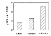
上記の焼結鍋による焼結実験の結果を図5および図6に示す。図5は、各焼結実験により製造された焼結鉱の落下強度の比較を示したもの、図6は、焼結鍋の異なる高さ位置4箇所(焼結ベッド下面を基準にそれぞれ150、250、350、450mmの各高さ位置)から焼結ベッド内に水平に挿入した熱電対によって測定された焼成中における焼結ベッド内各高さ位置における温度の経時変化から求めた保熱指数を焼結ベッド高さ位置に対してプロットしたものである。
【0045】
なお、焼結鉱の落下強度はJIS−M8711の冷間強度試験方法に基づいて測定した。一般に、同一の焼結原料を用いて同一のガス吸引条件で焼成しても焼結鍋試験装置の熱損失が大きいため、焼結鍋試験で焼成された焼結鉱(鍋試験焼結鉱)の落下強度は、実機焼結機で製造された焼結鉱(実機焼結鉱)の落下強度に比べて大幅に低くなることが知られている。本焼結鍋試験の場合には、鍋試験焼結鉱の落下強度は実機焼結鉱の落下強度より約40ポイント低くなることを過去の実績より把握おり、例えば、本発明例1の鍋試験焼結鉱の落下強度33%は、実機焼結鉱の落下強度約73%に相当する。
【0046】
また、「保熱指数」とは、測定された焼結ベッド各高さ位置における温度の経時変化の曲線から求まる最高到達温度を頂点とし、昇温時および降温時に通過する1100℃の2点を底辺として描かれる三角形の面積より算出した指数(単位:℃・min)であり、焼結反応に寄与する熱量を相対的に表す指標として用いるものである。
【0047】
図5より明らかなように、比較例では焼結鉱の落下強度は約31%であったものが、本発明例1では約33%、本発明例2ではさらに約38%に上昇し、本発明の効果が確認された。また、図6に示されるように、比較例では焼結ベッド上部から中部(焼結ベッド下面から450〜250mm高さ)にかけての保熱指数が極端に低くなっている。前述した高水分ガスの吸引の影響により上層部の温度上昇が阻害されるためと推測される。
【0048】
それに対して、本発明例1では、焼結ベッド上部(450mm高さ)の保熱指数が比較例に比して著しく上昇し、中部、下部についても比較例よりかなり高い値となった。上層部(焼結ベッド表面から焼結ベッド層厚の約18%までの深さ)に固体燃料(コークス粉)を焼結ベッド層厚全体の平均配合量より高く配合したことにより上層部の燃焼発熱量が増加したことによるものと推測される。これにより、落下強度が上昇したものといえる。
【0049】
また、本発明例2では、焼結ベッド層厚全体の保熱指数は本発明例1ほどには高くないが、比較例に比すれば高い値になった。上層部を圧密化したことによる焼成後の上層部の焼結構造が緻密化したことと相俟ってさらに落下強度が上昇したものと考えられる。
【0050】
(実施例2)
上記焼結鍋試験により本発明の効果を確認できたので、さらに本発明を排ガス循環方式(排ガス系を3分割)の実機焼結機に適用し、定量的な効果の確認を行なった。先ず、実機焼結機(図7参照)に上記第1発明(焼結ベッド上層部への固体燃料の選択的多量配置)の適用を行なった。用いた実機焼結機の各風箱群の風箱No.については、第1風箱群6Aは風箱No.1〜No.7、第2風箱群6Bは風箱No.8〜No.22、第3風箱群6Cは風箱No.23〜No.27である。また、循環ガスフード7の位置は、風箱No.3〜No.22の上方に相当する。図1に示す固体燃料散布装置21としては、本出願人が特願平10−356651号にて提案した図3に示す固体燃料散布装置を用いた。図3に示すように、この装置は、移動パレット2に積み付けられた焼結原料の上方に、その進行方向Gに対して横断する方向に分散板36が設けられている。分散板36は、その分散板36上に供給された固体燃料24を振動によってパレット横断方向Eへ移送する。分散板36のパレット進行方向板幅は、前記移送方向に向かって減少しており、上記移送される固体燃料24が次々と落下(F)し、焼結原料4上面に広範かつ均一に散布されるものである。この固体燃料分散装置21を用いて、焼結原料上面に散布する固体燃料(コークス粉)の量を順次増加し(その散布量に相当する量だけ焼結原料へのコークス粉の配合量を順次減少して)、製造される焼結鉱の落下強度および生産指数に及ぼす影響を調査した。ここに「生産指数」とは、固体燃料分散装置21によるコークス粉の添加を行なわない従来方法による生産量を基準(100%)として生産性を相対表示したものである。
【0051】
図8は、固体分散装置21で焼結原料上面にコークス粉を散布したあとカットプレート22でそのコークス粉と上層部の焼結原料とを混合した後の焼結ベッドの一部をサンプリングし、そのサンプルの異なる高さ位置ごとの固定炭素濃度を測定することにより、焼結ベッド高さ方向のコークス粉の分布状況を調査したものの一例である。なお、図8は、横軸および縦軸は無次元化して示している。すなわち、横軸の固定炭素濃度比は、測定された各固定炭素濃度を焼結ベッド全体の平均固定炭素濃度で割った値であり、縦軸の焼結ベッド高さ位置は、焼結ベッド下面からの各高さを焼結ベッド全層厚で割った値である。図8から明らかなように、コークス粉の散布を行なわない場合の固定炭素濃度分布に比較して、焼結ベッド上面から焼結ベッド層厚の約15%までの上層部のみ固定炭素濃度が高くなっており、所定の深さの上層部にコークス粉を選択的に多く配置できることを確認した。
【0052】
そこで、この固体燃料分散装置を用いて焼結原料上面に散布する固体燃料(コークス粉)の量を順次増加して焼結を行ない、図9の結果を得た。図9は、前記上層部の固体燃料配合率の焼結ベッド層厚全体の固体燃料平均配合率からの上乗せ分と製造された焼結鉱の落下強度および生産指数との関係を示したものである。図9から、前記上乗せ分を多くするほど焼結鉱の落下強度は上昇することを確認した。前記上乗せ分を多くするにしたがい、焼結ベッド上層部の脆化層の形成が減少する効果による。一方、生産指数は、前記上乗せ分を多くしていくと最初上昇するが、前記上乗せ分が約1質量%のときに最大となり、前記上乗せ分をさらに多くすると逆に低下することを確認した。このように前記上乗せ分がある一定値(約1質量%)までは生産指数が上昇するのは、前述したように焼結ベッド下部の熱バランスが改善され下部における過剰の融液の生成が回避されて通気性が向上するためであり、一方、前記上乗せ分が多すぎると生産指数が低下するのは、前述したように、上層部の融液の量が過剰になり焼結ベッドの通気性を阻害するためである。したがって、前記上乗せ分は、焼結鉱の落下強度が0.3%以上上昇して歩留りの改善効果が十分現れ、かつ生産指数も0.8%以上の上昇を確保できる0.5〜1.5質量%が好ましい。
【0053】
(実施例3)
次に、上記第2発明(焼結ベッド上層部への固体燃料の選択的多量配置+焼結ベッド表面の圧密)の定量的な効果を確認するため、前記実機焼結機に上記第2発明の適用を行なった(図2参照)。図2に示すように、実施例2の設備構成(図1参照)に、カットプレート22と点火炉5の間に圧密ローラー23を追加した。圧密ローラー23は、電動機にて駆動され任意の回転速度に調節でき、さらにローラーの軸の両端は上下に移動でき、ローラーの高さ位置の調整が可能な機構としている。
【0054】
移動パレット2上に装入された焼結原料は、まずカットプレート22でその表面が平滑化された後、さらに、所定の高さ位置に設定された圧密ローラー23でその表面が転圧される。なお、圧密ローラー23の回転速度を適宜調整することにより、圧密ローラー23による転圧後の焼結ベッド表面が波打たずできるだけ平滑なまま維持できる。上記固体燃料の上乗せ分を1%に固定したまま、圧密ローラー23の高さ位置を順次低下させて、全層厚に対する焼結ベッド表面の圧密割合を増加させたときの、焼結鉱の落下強度および生産指数に及ぼす影響を調査した。
【0055】
図10に、焼結ベッド表面の圧密割合と、製造された焼結鉱の落下強度および生産指数との関係を示す。図10から、焼結鉱の落下強度は、圧密割合を0%から順次大きくしていくと圧密割合が約7%に達するまでは加速度的に上昇するが、圧密割合が約7%を超えるとその上昇度合いは次第に小さくなり圧密割合が約9%を超えるとほとんど上昇しなくなることがわかった。一方、生産指数は、圧密割合を0%から順次大きくしていくにしたがって漸増するが、圧密割合が約7%でピークを示し、それを超えると急速に低下することがわかった。このように圧密割合が約7%を超えると焼結鉱の落下強度の上昇が鈍化し、かつ生産指数が低下するのは、表面近傍が緻密になりすぎたため充填層内で焼結機幅方向にガスの偏流が生じ十分焼結されない強度の弱い部分が存在し始め上層部の焼結鉱の落下強度の上昇分を希釈するとともに、通気抵抗が増大してガスの吸引量が少なくなりすぎ焼結速度が低下したためと推測される。したがって、圧密割合は、焼結鉱強度の改善効果が現れる約1%以上で、生産指数を上昇させつつ焼結鉱の落下強度が上昇できる、約7%以下とすることが好ましい。
【0056】
【発明の効果】
上記第1発明によれば、焼結ベッド表面から焼結ベッド層厚の15%までの上層部の固体燃料配合率を焼結ベッド全体の固体燃料の平均配合率より0.5〜1.5質量%高くすることにより、高水分の循環排ガスを吸引しても、生産性を向上させつつ、製品歩留りを向上させることができる。
【0057】
上記第2発明によれば、焼結ベッド表面から焼結ベッド層厚の15%までの上層部の固体燃料配合率を焼結ベッド全体の固体燃料の平均配合率より0.5〜1.5質量%高くし、さらに焼結ベッド表面を焼結ベッド層厚の1〜7%圧密することにより、上記と同じく生産性を向上させつつ、製品歩留りを一層向上させることができる。
【0058】
したがって、本発明により、系外に排出する排ガス量を一層削減しつつ、生産性、製品歩留りをともに向上でき、低コストで焼結鉱を製造できる排ガス循環方式焼結操業方法が確立できた。
【図面の簡単な説明】
【図1】 本発明(第1発明:焼結ベッド上層部への固体燃料の選択的多量配置)を実施するための排ガス循環方式焼結機の原料装入部近傍の概要を示す、概略説明図である。
【図2】 本発明(第2発明:焼結ベッド上層部への固体燃料の選択的多量配置+焼結ベッド表面の圧密)を実施するための排ガス循環方式焼結機の原料装入部の概要を示す、概略説明図である。
【図3】 本発明(第1および第2発明)における焼結ベッド上層部に固体燃料を選択的に多く配置するための固体燃料散布装置の概要を示す、概略説明図である。
【図4】 本発明(第1および第2発明)における焼結ベッド上層部に固体燃料を選択的に多く配置する装置の別の態様を示す、概略説明図である。
【図5】実施例1の、焼結鍋試験により製造された焼結鉱の落下強度を示す説明図である。
【図6】実施例1の、焼結鍋試験における焼結ベッド各高さ位置における保熱指数を示す説明図である。
【図7】実施例2および3の、本発明適用前の排ガス循環方式焼結機(排ガス系を3分割)の概略説明図である。
【図8】実施例2の、焼結ベッドの高さ方向での固体燃料の分布を示す説明図である。
【図9】実施例2の、焼結ベッド上層部への固体燃料配合率上乗せ分と焼結鉱の落下強度および生産指数との関係を示す説明図である。
【図10】実施例3の、焼結ベッド表面の圧密割合と焼結鉱の落下強度および生産指数との関係を示す説明図である。
【図11】大気吸引方式焼結機における排ガスの焼結機長手方向の温度変化、水分変化、および酸素濃度変化を示す概略説明図である。
【図12】排ガス循環方式焼結機の一例(排ガス系を2分割)の概略説明図である。
【図13】高水分ガス吸引時における燃焼部近傍の焼結鉱中FeO含有量の分布を示す説明図である。
【符号の説明】
1…焼結機、2…移動パレット、3…原料供給装置、4…焼結原料(焼結ベッド)、5…点火炉、6…風箱、6A…第1風箱群、6B…第2風箱群、6C…第3風箱群、7…循環ガスフード、8…低温ガス循環用排風機、9…高温ガス循環用排風機、10…主排風機、11A…循環ガスダクト、11B…循環ガスダクト、12…集塵機(電気集塵機)、13…煙突、14…排気ダクト、19…焼結原料(湿潤帯)、20…赤熱帯、21…固体燃料散布装置、22…カットプレート、23…圧密ローラー、24…固体燃料、25…固体燃料配合率の高い焼結原料層、35…固体燃料定量供給装置、36…分散板、41…焼結原料ホッパー、42…固体燃料ホッパー、43…ドラムフィーダー、44…装入シュート、45…固体燃料添加用ノズル、46…ガイドシュート、E…固体燃料移送方向、F…固体燃料落下方向、G…パレット進行方向[0001]
BACKGROUND OF THE INVENTION
The present invention relates to a method for operating a sintering machine in which the strength of sintered ore does not decrease even when high moisture gas is circulated to a sintering bed in the operation of an exhaust gas circulation type sintering machine.
[0002]
[Prior art]
In the following description, “water” in the exhaust gas means “water vapor” in the exhaust gas. For example, “
[0003]
The raw materials for the sintered ore are fine iron ore as an iron source, dust collection dust, mill scale, limestone as a solvent, dolomite, fine coke as solid fuel, anthracite, and the like. What mix | blended these is rolling-granulated with water and a binder with a drum mixer, and is set as the sintering raw material which consists of a particle | grain with an average particle diameter of 3-4 mm containing 6-7 mass% (outside number) of water. This sintering raw material is supplied to a sintering machine, and is continuously sintered by a dwelloid type sintering machine (DL type sintering machine). When producing sintered ore with a DL-type sintering machine, not a part of the exhaust gas generated by sintering is circulated, but the coke in the sintering raw material is burned only in the air (air) sucked downward. There are a sintering operation method by an atmospheric suction method and a sintering operation method by an exhaust gas circulation method in which a part of the exhaust gas is circulated for operation.
[0004]
In the sintering method using the air suction method, a sintered raw material is charged in a thickness of 50 to 60 cm onto a pallet that moves endlessly, and a raw material layer (firing) is produced in an ignition furnace by combustion heat such as coke oven gas or heavy oil. The coke on the surface is ignited, and the powder coke is burned by the air passing from the upper part to the lower part of the sintered bed by a group of wind boxes connected to the lower side of the pallet. While the sintering bed on the pallet moves to the discharge side, the combustion of the powder coke in the sintering bed proceeds from the upper layer to the lower layer, and when it reaches the discharge end of the sintering machine, It is intended to complete the tie.
[0005]
In general, in the case of the atmospheric suction method, the temperature change, moisture change, and oxygen concentration change in the longitudinal direction of the sintering machine of the exhaust gas that has passed through the sintering bed are as shown in FIG. That is, in the first half of the sintering machine, the raw material at the upper part of the sintering bed is heated and the water held in the raw material is evaporated and transferred into the gas. Therefore, the temperature of the exhaust gas that has passed through the sintering bed is as low as 50 to 60 ° C., and the moisture is as high as 5 to 16%. On the other hand, in the latter half of the sintering machine, the removal of water from the sintering bed is almost finished, and the high temperature part (combustion zone) 20 due to the combustion of the powder coke reaches the lower part of the sintering bed. Although it rises rapidly (up to about 460 ° C.), the water drops rapidly to 2-3%. The oxygen concentration is as high as 18 to 20% in the lower region of the
[0006]
The exhaust gas circulation system sintering operation method improves the disadvantages of the air suction system operation, reduces the amount of exhaust gas discharged from the sintering machine and the total amount of NOx from the viewpoint of environmental protection, and recovers exhaust gas heat. In order to improve productivity, the wind box group of the DL-type sintering machine is appropriately divided in the longitudinal direction of the sintering machine, and a part of the exhaust gas generated by the sintering is placed on the pallet of the sintering machine. In recent years, it has been widely adopted in recent years.
[0007]
For example, as shown in FIG. 12, the sintering machine exhaust gas system is divided into two in the machine length direction, and the exhaust gas having a high rear temperature and a relatively high oxygen concentration is circulated to the gas suction part of the sintering machine for reuse. In general, a method of reducing the amount of exhaust gas and recovering sensible heat of exhaust gas is performed. In such a method, since the exhaust gas having a temperature higher than that of the atmosphere is introduced from the top of the sintering bed, the degree of preheating of the raw material can be increased, but the temperature is generally in the range of 100 to 200 ° C., Since it is lower than the red-tropical temperature (over 1000 ° C), basically the cooling rate in the upper part of the sintering bed is in other parts (middle part, lower part) as in the case where exhaust gas is not circulated. Compared to larger. Therefore, also in the exhaust gas circulation sintering method, the yield of the upper layer portion tends to be relatively lowered as in the air suction sintering method. In addition, the exhaust gas circulation reduces the oxygen concentration in the introduced atmosphere (approximately 18% by volume) and reduces the combustion speed of the solid fuel, so that there is no heat propagation or accumulation effect from the top. It becomes a cause which promotes the yield fall in a tie bed upper layer part.
[0008]
Thus, as a method for improving the product yield in the exhaust gas circulation method, it has been proposed to improve the product yield by making the heat balance of the entire sintered bed appropriate. For example, Japanese Patent Application Laid-Open No. 7-278585 discloses a method in which the coke between the upper layer and the lower layer of the sintering bed is mixed in a gradient in the range of 0.7 to 1.2% in terms of segregation index depending on the exhaust gas circulation location and the circulation amount. Has been proposed. In addition, it has been proposed to adjust the blending ratio of +3 mm in the powdered coke to be blended at 1 to 10%.
[0009]
The coke slant blending method at this time employs a bear's hand-shaped sizing / dispersing charging device having a large number of bars described in Japanese Utility Model Publication No. 1-66599. In this method, a raw material with a large particle size is filled in the lower layer portion when the raw material is charged into the moving pallet, and the raw material with a smaller particle size is sequentially filled from the lower layer portion to the upper layer portion. And since powdery coke has adhered to the surface of the raw material particles, a larger amount of powdery coke adheres as the particle size of the raw material particles decreases and the surface area per volume increases. As a result, the amount of coke is higher in the upper layer than in the lower layer in a gradient composition.
[0010]
[Problems to be solved by the invention]
In Japanese Patent Application No. 2000-53803, the present applicant divided the sintering machine exhaust gas system into three parts instead of the conventional two parts, and not only the exhaust gas having a high temperature and a relatively high oxygen concentration in the rear region, but also the front region. A method has been proposed in which the amount of exhaust gas discharged outside the system can be further reduced by circulating an exhaust gas having a low temperature and high moisture but a relatively high oxygen concentration to the suction part of the sintering machine (see FIG. 7). In this method, the high temperature exhaust gas from the rear region further increases the degree of preheating of the raw material before sintering, and the oxygen in the exhaust gas from the front region and the rear region maintains and does not reduce the combustion rate of the solid fuel in the raw material It contributes to that.
[0011]
However, in this exhaust gas circulation method sintering method, the yield reduction of the upper part of the sintering bed is more significant than in the conventional exhaust gas circulation method sintering method in which the exhaust gas system is divided into two parts. It has been found that the yield of the upper layer portion cannot be sufficiently improved by the coke gradient blending method described in the Japanese Patent Publication.
[0012]
As a result of various studies on the cause of the remarkable yield reduction of the upper layer portion, the present inventors have found that high concentration of water contained in the circulating gas reduces the sinter strength (yield). In the exhaust gas circulation method sintering method, the moisture of the gas sucked into the sintering bed is at most 2 to 3% in the exhaust gas circulation method sintering operation method in which the conventional exhaust gas system is divided into two. Circulates high-moisture exhaust gas from the front area, reaching about 8-9% by volume. Therefore, by using the same sintering raw material as in the comparative example of Example 1 using the sintering pot test apparatus used in Example 1 described later, only the moisture in the suction gas was changed, and a sintering experiment was performed. The effect of the water content on the drop strength of the sintered ore was investigated. The results are shown in Table 1. As is clear from Table 1, the drop in strength of the sintered ore is small when the moisture in the suction gas is up to 6%, but when the moisture in the suction gas exceeds 6%, the drop strength of the sintered ore suddenly increases. It turns out that it falls.
[0013]
[Table 1]
When the moisture in the suction gas becomes high, the water gasification reaction and the water gas modification reaction shown by the following two reaction formulas become active in the red tropics (near the heat front).2The production amount of H increases.2Is hematite (Fe2OThree) Or magnetite (FeThreeOFour) Is promoted to increase the content of wustite (FeO) (see FIG. 10), and this wustite is the gangue component SiO in the raw ore.2And a low melting point compound is formed and melted to form a macro void having a diameter of about 5 mm to become an embrittled layer, and the strength of the sintered ore is significantly reduced.
[0015]
C + H2O → CO + H2 (Water gasification reaction)
CO + H2O → CO2+ H2 (Water gas shift reaction)
In addition, the solid fuel is consumed in the water gasification reaction to reduce the amount of combustion heat generated by the original oxygen, and this water gasification reaction is a large endothermic reaction, which amplifies the lack of heat supply at the top of the sintering bed. It is assumed that the yield reduction was promoted.
[0016]
The reason why the upper layer portion yield cannot be sufficiently prevented by the coke gradient blending method proposed in Japanese Patent Laid-Open No. 7-278585 is as follows. In this coke gradient blending method, when the raw material is charged, fine coke is granulated together with the fine raw material to form large particles (pseudo particles) with a large amount of coke, which are filled in the lower layer part of the sintering bed. From the upper layer part of the bed to the lower layer part, it is practically difficult to incline the coke depending on the purpose. Moreover, since the particle size of the coke distributed to an upper layer part is small, the heat-transfer efficiency to the ore which is a solid falls. In other words, coke with a small particle size burns fast, and heat transfer to air preferentially proceeds to heat transfer to solid ores, so the ore temperature does not rise sufficiently, and ore particles A sufficient melt bond strength cannot be obtained. Therefore, the improvement effect is small with respect to the exhaust gas circulation system sintering method which sucks the high moisture gas accompanied by a large strength reduction of the upper portion of the sintering bed.
[0017]
Therefore, the present applicant has studied the means for solving the above-mentioned problem, and in Japanese Patent Application No. 11-064661, in the exhaust gas circulation method, when filling the sintering raw material from the charging chute onto the moving pallet, By newly adding the solid fuel on the charging chute, the amount of the solid fuel in the upper layer portion of the sintering bed, particularly in the region from 50 to 100 mm from the surface of the sintering bed, is changed to the solid fuel in the lower layer region. The production method of the sintered ore which prevents the formation of the embrittlement layer formed in the upper layer part of a sintering bed by operating with the compounding quantity of more than was proposed. This method can surely add more solid fuel to the upper layer than the lower layer, and can easily change the thermal balance of the entire sintered bed. However, if the amount of new solid fuel added to the upper layer is small, the formation of the embrittlement layer cannot be completely prevented, so the yield is not improved sufficiently. On the other hand, if the amount of addition is too large, the lower layer is insufficiently heat-deficient. As a result, the yield deteriorates. Therefore, it is impossible to simply increase the amount of the solid fuel in the upper layer than that in the lower layer, and the yield has not been sufficiently improved.
[0018]
The present invention has been made in view of such circumstances, and in the exhaust gas circulation sintering method for circulating a high moisture gas, sintering with high product yield that prevents formation of an embrittlement layer formed in the upper layer portion of the sintering bed. It aims at providing the manufacturing method of an ore.
[0019]
[Means for Solving the Problems]
First to solve the above problemsThe invention is an exhaust gas circulation system sintering operation method in which a part of the exhaust gas from the sintering machine is circulated again to the sintering bed, and is present in the upper layer part from the surface of the sintering bed to approximately 15% below the sintering bed layer thickness. The exhaust gas circulation system sintering operation method is characterized in that the operation is performed with the solid fuel blending ratio being higher by 0.5 to 1.5 mass% than the average blending ratio of the solid fuel of the entire sintered bed layer thickness. .
[0020]
Second invention (Claim1Invention described in)In the exhaust gas circulation method sintering operation method in which a part of the exhaust gas from the sintering machine is circulated again to the sintering bed, the solid existing in the upper layer portion from the surface of the sintering bed to approximately 15% below the thickness of the sintering bed layer Sinter the surface of the sintering bed before the ignition of the sintering raw material by increasing the mixing ratio of the fuel by 0.5 to 1.5 mass% higher than the average mixing ratio of the solid fuel of the entire sintered bed layer thickness. The exhaust gas circulation system sintering operation method is characterized in that the operation is performed by compacting downward in a range of 1 to 7% of the bed layer thickness.
[0021]
By selectively disposing a large amount of solid fuel at a predetermined thickness (depth) of the upper part of the sintered bed, an appropriate heat balance can be obtained throughout the height direction of the sintered packed bed, and Formation of a fragile layer in the upper layer portion is prevented, product strength is increased, and product yield is improved. In addition, the blending ratio of the solid fuel at the bottom of the packed bed is lower than before, so excessive heat supply at the bottom of the packed bed is avoided, the formation of excess melt is prevented, and air permeability is improved, producing Also improves.
[0022]
Furthermore, by compacting the surface of the sintered bed downward by a predetermined thickness (depth), the sintered structure of the upper layer portion after firing becomes dense and the high temperature holding time of the upper layer portion is extended, so that the entire layer is Since the heat balance becomes more appropriate, the strength is further increased and the yield is improved.
[0023]
DETAILED DESCRIPTION OF THE INVENTION
FIG. 7 is a schematic explanatory diagram of an exhaust gas circulation type sintering machine proposed in Japanese Patent Application No. 2000-53803 before application of the present invention.
[0024]
The
[0025]
The wind box group includes a first
[0026]
The circulating
[0027]
The exhaust gas (main exhaust gas) from the second
[0028]
As described above, exhaust gas sensible heat is recovered by circulating the high temperature, low moisture exhaust gas from the third wind box group, and exhaust gas discharged outside the system by circulating the low temperature, high moisture exhaust gas from the first wind box group. The amount (exhaust gas amount) can be further reduced.
[0029]
Now, although the embrittlement layer produced by sintering exists in the upper layer part of a sintering bed, there exists a part which cannot be specified unconditionally because the existing depth varies depending on the sintering conditions. However, if the sintering conditions are operated within a substantially constant range, the embrittlement layer is generally generated at a depth of 5 to 10% of the total height of the sintering bed from the outermost surface of the sintering bed. And exist. Therefore, based on the location of the embrittlement layer, the upper layer part where the blending amount of the solid fuel is increased, considering the case where the embrittlement layer becomes deeper, the uppermost part of the sintering bed starts from It is preferable that the depth is up to about 15% of the total height. Moreover, if the blending amount of the solid fuel in the upper layer is higher than the average blending amount of the solid fuel in the entire sintered bed, the effect of preventing the formation of the embrittlement layer is small if the blending amount is too small. However, the temperature of the upper layer rises too much and the amount of melt produced becomes excessive, which deteriorates the air permeability and lowers the productivity. Therefore, it is preferable that the range of the above-described degree that productivity can be improved or maintained while preventing formation of the embrittlement layer is 0.5 to 1.5 mass% based on the experimental result of Example 2 described later.
[0030]
The blending ratio of the solid fuel existing in the upper layer portion from the surface of the sintering bed to approximately 15% below the sintering bed layer thickness is 0.5 to 1.5 mass from the average blending ratio of the solid fuel in the entire sintering bed. For example, the method shown in FIG. That is, the sintered
[0031]
In the case of the method of spraying the solid fuel on the sintered bed, it is not necessary to change the basic production conditions of the conventional sintered ore, and it is not preferable to influence the basic operation conditions. That is, in the present invention, it is preferable to change only the existing state of the solid fuel in the height direction of the sintered bed. Therefore, the blending amount of the entire solid fuel blended in the iron oxide raw material is constant so that the heat input to the iron oxide raw material is the same as the method for producing sintered ore that has not been applied to the present invention. (In other words, the average blending ratio of the solid fuel in the entire sintered bed is preferably constant). Therefore, in the present invention, the amount of solid fuel sprayed on the sintering bed is first set to the difference between the target solid fuel blending ratio of the upper layer and the average blending ratio of the solid fuel of the entire sintering bed. It determines by multiplying the quantity of the sintering raw material for the thickness (depth) of the upper layer part. Next, the amount of the solid fuel blended in advance with the iron oxide raw material may be set to an amount obtained by subtracting the spray amount from the amount blended with the entire sintered bed. In actual operation, the operating conditions such as the supply amount and particle size of the sintering raw material and the amount and particle size of the solid fuel to be applied are different, so the installation conditions (installation height, installation angle) of the soot and the
[0032]
As a result, an appropriate heat balance can be obtained throughout the height of the sintered bed, and the formation of a fragile layer in the upper layer of the sintered bed can be prevented without deteriorating productivity, resulting in an increase in product strength and product yield. It will also improve.
[0033]
In addition, the blending ratio of the solid fuel existing in the upper layer portion from the sintering bed surface to approximately 15% below the sintering bed layer thickness is set to 0.5 to 1.5 from the average blending ratio of the solid fuel in the entire sintering bed. As another means for increasing the mass%, it is possible to use an apparatus for adding solid fuel to the sintered raw material while the sintered raw material proposed in Japanese Patent Application No. 11-64661 flows down on the charging chute. Needless to say. As schematically shown in FIG. 4, in the method using this apparatus, the newly added
[0034]
In short, it is not limited to the above means as long as it is a means that can selectively dispose a large amount of solid fuel in the upper part of the sintered layer. When the present invention is applied to, for example, an existing actual machine sintering machine, It can be selected and changed as appropriate to suit the layout of the actual sintering machine equipment (especially charging equipment).
[0035]
It is preferable to adjust the particle size so that a substantial amount of the solid fuel existing in the upper layer portion of the sintering bed, for example, a particle size of 50% or more is 0.5 to 3 mm. The reason why the particle size adjustment of this solid fuel is preferable is that when the particle size of the solid fuel is less than 0.5 mm, the heat transfer of the combustion heat generated by burning the solid fuel is more than the radiant heat transfer to the ores that are solid. Since convective heat transfer to the gas passing through the packed bed is dominant, the temperature of the ore does not rise sufficiently, sufficient melt bonding between the ore particles cannot be obtained, and the strength may be reduced Because. On the other hand, if the particle size of the solid fuel exceeds 3 mm, the time until the solid fuel is ignited by the ignition burner becomes long, which may cause a reduction in production speed. Therefore, the above effect can be reliably exhibited by setting the solid fuel having an average particle size of 0.5 to 3 mm to a considerable amount, for example, 50% or more, relative to the amount of the solid fuel in the upper portion of the sintered bed. .
[0036]
More preferably, the sintering bed surface is consolidated downward in the range of 1 to 7% of the thickness of the sintering bed layer before igniting the sintering raw material. Here, “consolidate the surface of the sintered bed downward” means that the surface of the sintered bed is compacted by using a roller or the like to make only the surface of the sintered bed dense and reduce the thickness of the sintered bed layer. For example, “consolidate 7% below the sintered bed layer thickness” means that the layer thickness is reduced by 7% by compaction based on the sintered bed layer thickness before consolidation. Say. The reason why the range of consolidation is 1 to 7% of the sintered bed layer thickness is that, as shown in Example 3 described later, if the consolidation is less than 1% of the sintered bed layer thickness, This is because the range of densification of the sintered structure is small, and the suction amount of the circulating gas is hardly reduced, so that the high temperature holding time is hardly extended and the effect of improving the sinter strength is small. On the other hand, if the consolidation exceeds 7% of the thickness of the sintered bed layer, the time required for sintering the portion densified by the consolidation increases in the proportion of time required for the entire sintered bed to sinter. This is because the decline in productivity cannot be ignored.
[0037]
As a method for compacting the sintered bed, for example, a method using a compacting roller shown in FIG. 2 can be employed. The surface of the sintered bed whose surface is smoothed by the
[0038]
【Example】
Example 1
In order to confirm the effect of selective mass arrangement of the solid fuel on the upper part of the sintering bed of the present invention and further the effect of consolidation of the surface of the sintering bed, a so-called sintering pot test apparatus is used to sinter the exhaust gas circulation system. A sintering experiment was conducted with a suction gas having a low oxygen concentration and a high moisture, assuming operation.
[0039]
A sintering pot having an inner diameter of 320 mm was used for the sintering pot test. Iron ore having the chemical composition shown in Table 2 was used as the iron oxide raw material, and coke powder was used as the solid fuel. Three types of sintered raw materials differing only in the amount of coke powder produced by kneading them at the blending ratio shown in Table 3 were prepared. Coke powder having the same particle size (−5 mm, average particle size 1.5 mm) was used for the three types of sintered raw materials. As a comparative example to which the present invention is not applied, a sintering raw material having a coke powder mixing ratio of 3.2% (outside number) is charged into a sintering pan with a bed layer thickness of 550 mm, ignited with a COG burner, and then with a suction pressure of 15700 Pa. Firing was carried out by sucking a gas having an oxygen concentration, moisture and temperature adjusted on the assumption of circulating exhaust gas. Note that suction gas assuming circulating exhaust gas is N2The oxygen concentration was adjusted to 18% by adding gas, and a predetermined amount of water vapor was added to make the moisture 16%, and then heated to 200 ° C. with an electric heater. The moisture content of the suction gas is 16%, which is higher than the moisture content of the suction gas in the circulation gas hood of the gas circulation type sintering machine described above, which is 8-9%. This is to increase the degree of influence (adverse effect) and clearly confirm the effect of the present invention.
[0040]
In Invention Example 1,The firstIn order to confirm the effect of the invention (selective mass arrangement of solid fuel on the upper part of the sintering bed), the average mixing ratio of the coke powder of the entire sintering bed is 3.2% (outside number) as in the comparative example, First, a sintered raw material having a coke powder blending ratio of 3.0% (outside number) is charged for a layer thickness of 450 mm, and a coke powder blending ratio of 4.2% (outside number) (about 1 from the average blending ratio). % Of the sintered raw material was charged in a layer thickness of 100 mm (about 18% of the total layer thickness) and fired under the same suction gas conditions as in the comparative example.
[0041]
In the present invention example 2,Second aboveIn order to confirm the effect of the invention (selective mass arrangement of the solid fuel to the upper part of the sintering bed + consolidation of the surface of the sintering bed), after charging the same sintering raw material as Example 1 of the present invention into the sintering pan, The surface of the sintering bed was pressed downward with a disk-shaped plate slightly smaller than the inner diameter of the sintering pan, and compacted by 35 mm (about 6% of the total layer thickness), and the sintering experiment was performed under the same suction gas conditions as in the comparative example. went.
[0042]
[Table 2]
[Table 3]
The result of the sintering experiment using the above-described sintering pot is shown in FIGS. FIG. 5 shows a comparison of the drop strengths of sintered ore manufactured by each sintering experiment, and FIG. 6 shows four different height positions of the sintering pot (150, respectively, based on the lower surface of the sintering bed, The heat retention index determined from the change over time of the temperature at each height position in the sintering bed during firing measured by a thermocouple inserted horizontally into the sintering bed from each height position of 250, 350, 450 mm) It is plotted against the sintered bed height position.
[0045]
In addition, the drop strength of the sintered ore was measured based on the cold strength test method of JIS-M8711. In general, even if the same sintering raw material is used and fired under the same gas suction conditions, the heat loss of the sintering pot test equipment is large, so the sintered ore fired in the sintering pot test (pot test sintered ore) It is known that the drop strength of is significantly lower than the drop strength of sintered ore (actual sintered ore) manufactured by an actual sintering machine. In the case of the main sintering pot test, it is known from the past results that the drop strength of the pot test sintered ore is about 40 points lower than that of the actual sintered ore. The drop strength 33% of the sintered ore corresponds to the drop strength of about 73% of the actual sintered ore.
[0046]
The “heat retention index” refers to two points of 1100 ° C. that pass when the temperature rises and falls, with the highest temperature obtained from the curve of temperature change at each height position of the measured sintering bed as the peak. This is an index (unit: ° C./min) calculated from the area of the triangle drawn as the base, and is used as an index that relatively represents the amount of heat contributing to the sintering reaction.
[0047]
As is clear from FIG. 5, the drop strength of the sintered ore was about 31% in the comparative example, but increased to about 33% in the present invention example 1 and further to about 38% in the present invention example 2. The effect of the invention was confirmed. Further, as shown in FIG. 6, in the comparative example, the heat retention index from the upper part of the sintering bed to the middle part (450 to 250 mm height from the lower surface of the sintering bed) is extremely low. It is presumed that the temperature rise of the upper layer is hindered by the influence of the high moisture gas suction described above.
[0048]
On the other hand, in Example 1 of the present invention, the heat retention index at the upper part (450 mm height) of the sintering bed was significantly increased as compared with the comparative example, and the middle part and the lower part were considerably higher than the comparative example. Combustion of the upper layer portion by blending solid fuel (coke powder) in the upper layer portion (depth from the sintered bed surface to about 18% of the sintered bed layer thickness) higher than the average blending amount of the entire sintered bed layer thickness This is presumably due to an increase in the amount of heat generation. Thereby, it can be said that the drop strength has increased.
[0049]
In Invention Example 2, the heat retention index of the entire sintered bed layer thickness was not as high as that of Invention Example 1, but was higher than that of Comparative Example. It is considered that the drop strength further increased in combination with the densification of the sintered structure of the upper layer portion after firing due to the consolidation of the upper layer portion.
[0050]
(Example 2)
Since the effect of the present invention could be confirmed by the above-mentioned sintering pot test, the present invention was further applied to an actual sintering machine of an exhaust gas circulation system (exhaust gas system divided into 3 parts) to confirm the quantitative effect. First, the actual machine sintering machine (see Fig. 7)The firstApplication of the invention (selective mass arrangement of solid fuel to the upper part of the sintering bed) was carried out. Wind box No. of each wind box group of the actual sintering machine used. For the first
[0051]
FIG. 8 shows a sample of a portion of the sintering bed after the coke powder is dispersed on the upper surface of the sintered raw material by the solid dispersion device 21 and the coke powder and the upper layer sintered raw material are mixed by the
[0052]
Therefore, sintering was performed by sequentially increasing the amount of solid fuel (coke powder) sprayed on the upper surface of the sintered raw material using this solid fuel dispersing apparatus, and the result of FIG. 9 was obtained. FIG. 9 shows the relationship between the solid fuel blending ratio of the upper layer from the average solid fuel blending ratio of the entire sintered bed layer thickness and the drop strength and production index of the manufactured sintered ore. is there. From FIG. 9, it was confirmed that the drop strength of the sintered ore increased as the added amount increased. This is due to the effect of reducing the formation of the embrittlement layer in the upper layer portion of the sintered bed as the amount of addition is increased. On the other hand, it was confirmed that the production index first increases as the added amount increases, but reaches a maximum when the added amount is about 1% by mass, and decreases when the added amount is further increased. In this way, the production index rises up to a certain value (about 1% by mass) as described above. The heat balance at the lower part of the sintering bed is improved as described above, and the formation of excessive melt at the lower part is avoided. On the other hand, as described above, the production index decreases when the added amount is excessive. As described above, the amount of the melt in the upper layer becomes excessive, and the air permeability of the sintered bed is reduced. It is for inhibiting. Therefore, the added amount can increase the drop strength of the sintered ore by 0.3% or more to sufficiently improve the yield, and the production index can be ensured to increase by 0.8% or more. 5 mass% is preferable.
[0053]
(Example 3)
next,The second invention(Selective mass placement of solid fuel on the upper part of the sintering bed + consolidation of the sintering bed surface)ofIn order to confirm the quantitative effect, the actual machine sintering machineSecond aboveThe invention was applied (see FIG. 2). As shown in FIG. 2, a compacting
[0054]
The sintered raw material charged on the moving
[0055]
FIG. 10 shows the relationship between the consolidation ratio of the sintered bed surface, the drop strength of the produced sintered ore, and the production index. From FIG. 10, the drop strength of the sintered ore increases at an increasing rate until the consolidation ratio reaches about 7% when the consolidation ratio is increased from 0%, but when the consolidation ratio exceeds about 7%. It was found that the degree of increase gradually decreased and hardly increased when the consolidation ratio exceeded about 9%. On the other hand, it was found that the production index gradually increased as the consolidation ratio was gradually increased from 0%, but showed a peak at the consolidation ratio of about 7% and rapidly decreased when the consolidation ratio was exceeded. Thus, when the consolidation ratio exceeds about 7%, the increase in the drop strength of the sintered ore slows down and the production index decreases because the vicinity of the surface becomes too dense and the width direction of the sintering machine is within the packed bed. As a result, gas weakly flows and there is a weak portion that does not sinter enough and dilutes the increase in fall strength of the upper ore sintered ore. This is presumed to be due to a decrease in the setting speed. Therefore, the consolidation ratio is preferably about 1% or more where the effect of improving the strength of the sinter is exhibited, and is preferably about 7% or less, which can increase the drop strength of the sinter while increasing the production index.
[0056]
【The invention's effect】
The firstAccording to the invention, the solid fuel blending ratio in the upper layer portion from the sintering bed surface to 15% of the sintering bed layer thickness is 0.5 to 1.5 mass% higher than the average blending ratio of the solid fuel in the entire sintering bed. As a result, even if high-moisture circulating exhaust gas is sucked, the product yield can be improved while improving the productivity.
[0057]
Second aboveAccording to the invention, the solid fuel blending ratio in the upper layer portion from the sintering bed surface to 15% of the sintering bed layer thickness is 0.5 to 1.5 mass% higher than the average blending ratio of the solid fuel in the entire sintering bed. Further, by compacting the sintered bed surface by 1 to 7% of the sintered bed layer thickness, the product yield can be further improved while improving the productivity as described above.
[0058]
Therefore, according to the present invention, an exhaust gas circulation type sintering operation method capable of improving both productivity and product yield and producing sintered ore at low cost while further reducing the amount of exhaust gas discharged outside the system can be established.
[Brief description of the drawings]
[FIG. 1] The present invention (1st inventionFIG. 3 is a schematic explanatory view showing an outline of the vicinity of a raw material charging portion of an exhaust gas circulation type sintering machine for carrying out (selective large-scale arrangement of solid fuel on a sintering bed upper layer portion).
[Fig. 2] The present invention (Second inventionFIG. 4 is a schematic explanatory diagram showing an outline of a raw material charging portion of an exhaust gas circulation type sintering machine for carrying out (selective large-volume arrangement of solid fuel on a sintering bed upper layer + consolidation of a sintering bed surface).
[Fig. 3] The present invention (1st and 2nd inventionFIG. 2 is a schematic explanatory view showing an outline of a solid fuel spraying device for selectively arranging a large amount of solid fuel in the upper layer portion of the sintered bed in FIG.
[Fig. 4] The present invention (1st and 2nd inventionFIG. 8 is a schematic explanatory view showing another aspect of an apparatus for selectively arranging a large amount of solid fuel in the upper layer portion of the sintered bed in FIG.
5 is an explanatory diagram showing the drop strength of sintered ore manufactured by a sintering pot test in Example 1. FIG.
6 is an explanatory view showing a heat retention index at each height position of the sintering bed in the sintering pot test of Example 1. FIG.
FIG. 7 is a schematic explanatory diagram of an exhaust gas circulation type sintering machine (exhaust gas system divided into three parts) before application of the present invention in Examples 2 and 3.
FIG. 8 is an explanatory diagram showing the distribution of solid fuel in the height direction of the sintered bed in Example 2.
FIG. 9 is an explanatory diagram showing the relationship between the amount of solid fuel added to the upper part of the sintered bed, the drop strength of the sintered ore, and the production index in Example 2.
10 is an explanatory diagram showing the relationship between the consolidation ratio of the sintered bed surface, the drop strength of the sintered ore, and the production index in Example 3. FIG.
FIG. 11 is a schematic explanatory view showing temperature change, moisture change, and oxygen concentration change in the longitudinal direction of the exhaust gas in the atmospheric suction type sintering machine.
FIG. 12 is a schematic explanatory diagram of an example of an exhaust gas circulation type sintering machine (exhaust gas system is divided into two parts).
FIG. 13 is an explanatory diagram showing a distribution of FeO content in sintered ore in the vicinity of a combustion portion during high moisture gas suction.
[Explanation of symbols]
DESCRIPTION OF
Claims (1)
Priority Applications (1)
| Application Number | Priority Date | Filing Date | Title |
|---|---|---|---|
| JP2000315158A JP3721068B2 (en) | 2000-10-16 | 2000-10-16 | Exhaust gas circulation method sintering operation method |
Applications Claiming Priority (1)
| Application Number | Priority Date | Filing Date | Title |
|---|---|---|---|
| JP2000315158A JP3721068B2 (en) | 2000-10-16 | 2000-10-16 | Exhaust gas circulation method sintering operation method |
Publications (2)
| Publication Number | Publication Date |
|---|---|
| JP2002121620A JP2002121620A (en) | 2002-04-26 |
| JP3721068B2 true JP3721068B2 (en) | 2005-11-30 |
Family
ID=18794304
Family Applications (1)
| Application Number | Title | Priority Date | Filing Date |
|---|---|---|---|
| JP2000315158A Expired - Lifetime JP3721068B2 (en) | 2000-10-16 | 2000-10-16 | Exhaust gas circulation method sintering operation method |
Country Status (1)
| Country | Link |
|---|---|
| JP (1) | JP3721068B2 (en) |
Families Citing this family (9)
| Publication number | Priority date | Publication date | Assignee | Title |
|---|---|---|---|---|
| JP5168802B2 (en) * | 2005-11-25 | 2013-03-27 | Jfeスチール株式会社 | Method for producing sintered ore |
| KR100722399B1 (en) * | 2005-12-26 | 2007-05-28 | 주식회사 포스코 | Sintered ore charging device |
| AT503199B1 (en) * | 2006-01-19 | 2008-02-15 | Voest Alpine Ind Anlagen | METHOD FOR SINTERING ON A SINTERING MACHINE |
| DE102008051063B4 (en) * | 2008-10-09 | 2014-08-21 | Outotec Oyj | Device for smoothing the surface of a sintered mixture |
| JP5811936B2 (en) * | 2012-04-13 | 2015-11-11 | 新日鐵住金株式会社 | Method for producing sintered ore |
| JP6001487B2 (en) * | 2013-03-29 | 2016-10-05 | 株式会社神戸製鋼所 | Method for producing sintered ore for iron making |
| RU2614475C2 (en) * | 2015-09-03 | 2017-03-28 | Открытое акционерное общество "Научно-исследовательский институт металлургической теплотехники" (ОАО "ВНИИМТ") | Charge igniting method and furnace for its implementation |
| CN109564065A (en) * | 2016-07-29 | 2019-04-02 | 株式会社Posco | Agglomerating plant and the method for manufacturing sinter using the agglomerating plant |
| KR101862150B1 (en) * | 2016-08-04 | 2018-05-31 | 주식회사 포스코 | sintering apparatus and method for manufacturing sintered ore of using it |
-
2000
- 2000-10-16 JP JP2000315158A patent/JP3721068B2/en not_active Expired - Lifetime
Also Published As
| Publication number | Publication date |
|---|---|
| JP2002121620A (en) | 2002-04-26 |
Similar Documents
| Publication | Publication Date | Title |
|---|---|---|
| JP5194378B2 (en) | Method for producing sintered ore | |
| CN1327072A (en) | Method and device for making metal iron | |
| JP3721068B2 (en) | Exhaust gas circulation method sintering operation method | |
| JP2009097027A (en) | Method for producing sintered ore | |
| CN1048758C (en) | Sintered steel manufacturing process | |
| JP3930570B2 (en) | Method for producing sintered ore and sintering machine therefor | |
| JP4470490B2 (en) | Method for producing semi-reduced agglomerate | |
| JP4918754B2 (en) | Semi-reduced sintered ore and method for producing the same | |
| JP5703715B2 (en) | Method for producing sintered ore | |
| JP2007119841A (en) | Method for manufacturing half-reduced and sintered ore | |
| WO1994005817A1 (en) | Method for producing sintered ore | |
| JP3397091B2 (en) | Sinter production method | |
| JP3879408B2 (en) | Method for producing sintered ore and sintered ore | |
| JP7095561B2 (en) | Sintered ore manufacturing method | |
| JP4379083B2 (en) | Method for producing semi-reduced agglomerate | |
| JP2510555B2 (en) | Blast furnace charging raw material sintering method | |
| CN217636810U (en) | Sintering machine capable of improving sintering yield | |
| JPH11209827A (en) | Production of sintered ore | |
| JP3531464B2 (en) | Method for producing sintered ore with low SiO2 content | |
| JP3651270B2 (en) | Blast furnace operation method using low SiO2 sintered ore | |
| JP4501656B2 (en) | Method for producing sintered ore | |
| JP4639436B2 (en) | Pallet for sintering machine | |
| JP5831694B2 (en) | Sintering machine | |
| JP3355967B2 (en) | Method for producing reduced iron | |
| KR101723446B1 (en) | Raw material processing method and Raw material processing apparatus |
Legal Events
| Date | Code | Title | Description |
|---|---|---|---|
| A621 | Written request for application examination |
Free format text: JAPANESE INTERMEDIATE CODE: A621 Effective date: 20040401 |
|
| A977 | Report on retrieval |
Free format text: JAPANESE INTERMEDIATE CODE: A971007 Effective date: 20050519 |
|
| A131 | Notification of reasons for refusal |
Free format text: JAPANESE INTERMEDIATE CODE: A131 Effective date: 20050524 |
|
| A521 | Written amendment |
Free format text: JAPANESE INTERMEDIATE CODE: A523 Effective date: 20050707 |
|
| TRDD | Decision of grant or rejection written | ||
| A01 | Written decision to grant a patent or to grant a registration (utility model) |
Free format text: JAPANESE INTERMEDIATE CODE: A01 Effective date: 20050830 |
|
| A61 | First payment of annual fees (during grant procedure) |
Free format text: JAPANESE INTERMEDIATE CODE: A61 Effective date: 20050909 |
|
| R150 | Certificate of patent or registration of utility model |
Free format text: JAPANESE INTERMEDIATE CODE: R150 Ref document number: 3721068 Country of ref document: JP Free format text: JAPANESE INTERMEDIATE CODE: R150 |
|
| FPAY | Renewal fee payment (event date is renewal date of database) |
Free format text: PAYMENT UNTIL: 20080916 Year of fee payment: 3 |
|
| FPAY | Renewal fee payment (event date is renewal date of database) |
Free format text: PAYMENT UNTIL: 20090916 Year of fee payment: 4 |
|
| FPAY | Renewal fee payment (event date is renewal date of database) |
Free format text: PAYMENT UNTIL: 20090916 Year of fee payment: 4 |
|
| FPAY | Renewal fee payment (event date is renewal date of database) |
Free format text: PAYMENT UNTIL: 20100916 Year of fee payment: 5 |
|
| FPAY | Renewal fee payment (event date is renewal date of database) |
Free format text: PAYMENT UNTIL: 20100916 Year of fee payment: 5 |
|
| FPAY | Renewal fee payment (event date is renewal date of database) |
Free format text: PAYMENT UNTIL: 20110916 Year of fee payment: 6 |
|
| FPAY | Renewal fee payment (event date is renewal date of database) |
Free format text: PAYMENT UNTIL: 20110916 Year of fee payment: 6 |
|
| FPAY | Renewal fee payment (event date is renewal date of database) |
Free format text: PAYMENT UNTIL: 20120916 Year of fee payment: 7 |
|
| FPAY | Renewal fee payment (event date is renewal date of database) |
Free format text: PAYMENT UNTIL: 20120916 Year of fee payment: 7 |
|
| FPAY | Renewal fee payment (event date is renewal date of database) |
Free format text: PAYMENT UNTIL: 20130916 Year of fee payment: 8 |