JP3717180B2 - Bicycle hand drive device - Google Patents
Bicycle hand drive device Download PDFInfo
- Publication number
- JP3717180B2 JP3717180B2 JP51405596A JP51405596A JP3717180B2 JP 3717180 B2 JP3717180 B2 JP 3717180B2 JP 51405596 A JP51405596 A JP 51405596A JP 51405596 A JP51405596 A JP 51405596A JP 3717180 B2 JP3717180 B2 JP 3717180B2
- Authority
- JP
- Japan
- Prior art keywords
- pedal
- bicycle
- connecting rod
- pair
- lever
- Prior art date
- Legal status (The legal status is an assumption and is not a legal conclusion. Google has not performed a legal analysis and makes no representation as to the accuracy of the status listed.)
- Expired - Fee Related
Links
Images


Classifications
-
- B—PERFORMING OPERATIONS; TRANSPORTING
- B60—VEHICLES IN GENERAL
- B60C—VEHICLE TYRES; TYRE INFLATION; TYRE CHANGING; CONNECTING VALVES TO INFLATABLE ELASTIC BODIES IN GENERAL; DEVICES OR ARRANGEMENTS RELATED TO TYRES
- B60C23/00—Devices for measuring, signalling, controlling, or distributing tyre pressure or temperature, specially adapted for mounting on vehicles; Arrangement of tyre inflating devices on vehicles, e.g. of pumps or of tanks; Tyre cooling arrangements
-
- B—PERFORMING OPERATIONS; TRANSPORTING
- B62—LAND VEHICLES FOR TRAVELLING OTHERWISE THAN ON RAILS
- B62M—RIDER PROPULSION OF WHEELED VEHICLES OR SLEDGES; POWERED PROPULSION OF SLEDGES OR SINGLE-TRACK CYCLES; TRANSMISSIONS SPECIALLY ADAPTED FOR SUCH VEHICLES
- B62M1/00—Rider propulsion of wheeled vehicles
- B62M1/12—Rider propulsion of wheeled vehicles operated by both hand and foot power
Abstract
Description
発明の分野
本発明は、一般に、自転車に関する。特に、本発明は、自転車の着脱可能ハンドドライブ装置に関する。
発明の背景
ますます多くのアメリカ人が、毎日、自転車に乗っている。健康のために自転車に乗る人もあれば、大気汚染減少に寄与し環境向上のために乗る人もある。しかし、自転車に乗る理由に関わらず、人が自転車に乗っている間、活動し仕事のすべてを行うのは、自転車のライダーの脚および下半身である。このため、自転車をこいでいる人が疲れることになり、自転車に乗っている間、全身ではなくて、脚の運動だけを行うことになり得る。また、時には、足の力および手の力の両方が、上り坂を走行する際に有用であり得る。
ハンドドライブ機器を有する自転車が、当該分野で公知である。これらの特許の初期のものの1つは、1896年11月10日発行のPettinatiの米国特許第571,051号に開示されている。Pettinatiにおいて、自転車のフレームに取り付けられた点のまわりを回動し、レバーを介して自転車のクランクに接続される補助ハンドルバーが、設けられ、これにより、自転車のライダーは、脚および腕で自転車を動かすことが可能である。
自転車を手で動かす別の初期の手法が、1929年6月22日発行のFerriのフランス特許第658,967号に開示されている。Ferriは、自転車フレームに回動的に装着され、第2のレバーによって自転車のペダルに接続された一対のハンドルレバーを有し、これにより、自転車を動かすための自転車のライダーの脚の使用を増大させる自転車を教示している。しかし、Pettinatiとは違って、Ferriの特許は、ハンドドライブ装置が、自転車のハンドルバーの代替物として働く自転車を教示している。
別の初期の手で動かす自転車が、Hortonの英国特許第8247号に開示されている。Hortonにおいて、一対のハンドルバーならびに自転車フレームおよびペダルに取り付けられたハンドパワーアセンブリを有する自転車が、開示されている。しかし、PettinatiおよびFerriの特許と同様に、Hortonの発明が、自転車から取り外されるときは必ず、自転車のペダルまたは他の部分を取り外さなければならないので、ハンドパワー装置なしで自転車に乗ることができない。
先行技術の共通の問題は、ハンドパワー装置またはアセンブリは、自転車に取り付けられると、装置が作動し続け、レバーが、走行の間、自転車のペダルまたは自転車のクランクの動きと共に動くことである。従って、自転車のハンドパワーアセンブリは、動き続けるので、使用されていないとき、自転車およびハンドパワーアセンブリの両方を動かすために、自転車のライダーは付加的な脚の力が必要である。また、先行技術のハンドパワー自転車において、ハンドパワーアセンブリは、使用されていないとき、自転車のライダーの前方にあるので、自転車走行プロセスの補助というよりむしろ障害になる。
従って、従来の自転車に素早く設置され、自転車から素早くかつ簡単に取り外され得、もし、自転車のライダーが、腕の運動を望まないなら、あるいは、腕または手の力でペダルを踏む努力を増大させることを望まないなら、アセンブリを自転車から取り外し得る、自転車のハンドドライブ装置が必要とされている。
発明の要旨
本願に開示された本発明は、任意の新規または既存の自転車に素早くかつ簡単に係合または改装され得、自転車のライダーの脚の使用のみで自転車を動かすことが所望であるときは、素早くかつ簡単に取り外され得る機構を設けることによって、先行技術の問題を克服する。
本発明は、1対の中心を回動するレバーの上端部に回動的に取り付けられた2つのハンドルレバーを有する1対のレバーを備えている。回動レバーの下端部は、1対のペダル接続ロッドに回動的に取り付けられ、ペダル接続ロッドの端部が、自転車のフットペダルの心棒上に着脱可能に回動的に支持される。1対のレバーは、着脱可能なT字形ブラケットによって自転車に関し定位置に回動的に固定され、直立の柄によって自転車フレームに固定される。ペダル接続ロッドの端部は、各自転車のペダルの軸シャフトに載せるためのノッチ部分を備え、ストップが、ペダル接続ロッド固定具を定位置に保持するために各ペダル接続ロッドの端部に形成される。
ペダル接続ロッド固定具は、ペダル接続ロッドの上を滑り、ストップの方向に移動し、ストップにより定位置に保持され、ペダル接続ロッドに形成されたノッチの底を閉じ、自転車ペダルの軸シャフトにペダル接続ロッドを固定する。ハンドルレバーの端部の直立ハンドルにより、ライダーが、手および腕の動きによって選択的にレバーを操作して装置を動かし自転車を操縦することが可能になる。
自転車のハンドドライブ装置をこのように構成することによって、ハンドドライブ装置は、自転車ペダルの軸シャフト上にペダル接続ロッドのノッチを載せ、ペダル接続ロッド固定具をペダル接続ロッド上のストップまで下方に滑らせ、一方、2つの固定板が、T字形ブラケットをフレームおよび自転車フレームの操縦ヘッドに保持することによって自転車に素早く取り付け得る。その後、自転車が使用され、脚の力および手の力の両方によって推進され得る。ハンドドライブ装置を自転車から取り外すことが所望であるとき、またはそれが所望であるなら、ペダルレベル固定具が、前方に滑り、ペダル接続ロッドが、自転車ペダル心棒から取り外され、アセンブリのT字形のブラケットが、固定板から外されるか、または固定板自体が、自転車フレームから取り外され得る。従って、この自転車ハンドドライブ装置は、ほとんどの任意の従来の自転車で使用され得、脚の力のみで自転車をこぐことを望むとき、素早くかつ簡単に自転車から取り外され得る機構を提供する。
従って、本発明の目的は、任意の新規または既存の自転車に素早くかつ簡単に係合し得る、自転車のよりよいハンドドライブ装置を提供することである。
本発明の別の目的は、自転車を動かす際、自転車のライダーの足の力を増大させるために、自転車のライダーの手および腕の力を自転車のクランクに伝達させる自転車のハンドドライブ装置を提供することである。
本発明のさらに別の目的は、自転車のライダーをその意図する目的地に運ぶ間、自転車のライダーの上半身の運動のために用いられ得る、自転車のハンドドライブ装置を提供することである。
本発明のさらなる目的は、製造が安価で、構造に耐久性があり、操作が効率的であり、メインテナンスが少なくて済む、自転車のハンドドライブ装置を提供することである。
本発明のさらに別の目的は、自転車を動かすために1つの手または両手で使用され得る、自転車のハンドドライブのための機器を提供することである。
本発明のこれらのおよび他の目的、特徴および利点は、添付の図面を参照して考慮すると、以下の説明から明らかである。いくつかの図面において、同一部分は、同じ参照符号で表される。
好適な実施態様の詳細な説明
図1は、本発明によって構成された自転車のハンドドライブ装置の部分斜視図の側立面図である。
図2は、図1に示すハンドドライブ装置のハンドルレバーの斜視図である。
図3は、図1に示すハンドドライブ装置の回動レバーの斜視図である。
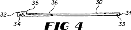
図4は、図1に示すハンドドライブ装置のペダル接続ロッドの斜視図である。
図5は、図1に示すハンドドライブ装置のT字形ブラケットの斜視図である。
図6は、図1に示すハンドドライブ装置の固定板の斜視図である。
図7は、ハンドドライブ装置を互いに固定するために使用される固定具の斜視図である。
図8は、回動レバーをT字形ブラケットに固定するために使用される固定具の斜視図である。
図9は、本発明の固定板を互いに固定するために使用される固定具の斜視図である。
図10は、ペダルレベル固定具の斜視図である。
図11は、自転車ペダルの軸シャフト上に置かれたペダル接続ロッドおよびペダル接続ロッド固定具の斜視図である。
詳細な説明
図面を詳細に参照すると、図1の符号5は、自転車のハンドドライブ装置の好適な実施態様を示す。ハンドドライブ装置5は、フレーム8、傾斜フレーム部材10、操縦ヘッドまたは操縦ハブ12、フレーム8に回転可能に取り付けられたフットクランク機構および該フットクランク機構に回転可能に接続されるペダル13を有する従来の自転車7に取り付けられる。各ペダルは、その中心を貫通して形成される軸シャフト14を備える。
図1を参照すると、ハンドドライブ装置5は、1対の離れたハンドルレバー15、1対の離れた回動レバー22、1対の離れたペダル接続ロッド30および各ペダル接続ロッド30の端部に滑動可能に装着される1対のペダル接続ロッド固定具38を備える。ハンドドライブ装置5はまた、1対の対向する固定板50によって自転車7のフレーム8および操縦ハブ12に固定されるT字形ブラケット40を備える。
ハンドルレバー15は、図2に最適に示される。ハンドルレバー15は、第1の端部16および第2の端部17を有する。図示されるように、ハンドルレバー15の第1の端部16は、第2の端部17から90度上に曲がり、第1の端部16の上のハンドル19は、ハンドルレバーの第2の端部17にほぼ垂直である。孔部20は、ハンドルレバー15の第2の端部17に形成され、ハンドルレバー15を回動レバー22に回動的に接続するためにそれを貫通している。
回動レバー22が、図3に示される。回動レバー22は、第1の端部23および第2の端部24を有する細長い棒またはロッドである。1対の同一の孔部26が、回動レバーの各端部に1つずつ形成される。各孔部26は、それぞれ、回動レバー22の第1および第2の端部を貫通する。回動レバー22はまた、回動レバー22の端部23および24の中間に位置する回動孔部28を備える。図3に示すように、該回動孔部28は、回動レバーの中央に示される。しかし、回動孔部28は、自転車7の使用中、ハンドドライブ装置5のレバー活動効果を増加または減少させるために、回動レバー22の長さに沿った他の位置に位置し得る。
図4を参照すると、ペダル接続ロッド30が示されている。ペダル接続ロッド30は、回動レバー22と同様に、第1の端部31および第2の端部32を有する細長い棒またはロッドである。孔部33が、ペダル接続ロッドの第1の端部31に形成され、完全に貫通している。ペダル接続ロッド30の第2の端部32には、自転車ペダル13の軸シャフト14(図11)上に係合するような大きさおよび形状を有するアーチ形ノッチ34が形成されている。ペダル接続ロッド30にはまた、第2の端部32にストップ35が形成されている。ストップ35は、ペダル接続ロッド30と同じ幅を有する。しかし、ストップ35は、ストップとして、かつペダル接続ロッド30の適切な位置にペダルレベル固定具38を配置させるための位置決め装置として機能するように、ペダル接続ロッド30の上表面36より上に上がっている。ペダル接続ロッド30の上表面36の上のストップ35の高さは、以下に詳細に説明するように、ペダル接続ロッド固定具38のケース部74の高さに相当する。
ハンドドライブ装置5のT字形ブラケット40が、図5に示される。T字形ブラケット40は、第1の端部41および第2の端部42を有する。T字形ブラケットの第1の端部41は、円形の管または棒から構成され、回動レバー22のそれぞれを自転車7のフレーム8の上部に固定空間関係で保持し、かつ間隔を保つのに十分な幅の水平部44を有する。さらに、水平部44の幅は、図11に示すように、ペダル接続ロッド30が、正確な間隔を保って、自転車クランクアセンブリの各ペダルの各軸シャフト14に置かれるように、自転車クランクアセンブリの幅と関連して決定される。垂直部47は、水平部44の中央に接続され、傾斜部48に向かって下方に伸びる。傾斜部48は、T字形ブラケット40を固定板50に保持する固定具66および68を受け入れるための2つの孔部49を有する。孔部49のそれぞれは、T字形ブラケット40の第2の端部42を貫通している。
T字形ブラケット40を、従って、ハンドドライブ装置5を自転車7に固定する固定板50が、図1および図6の両方に示される。図6を参照すると、固定板50は、第1の端部51および第2の端部52を有して示されている。固定板50の第1の端部および第2の端部の中間に、固定板50の水平方向の長さに関してほぼ斜めの位置に向けられたアーチ部54がある。リッジ部56が、固定板50の水平および長手方向軸に沿って位置し、自転車フレーム8の傾斜フレーム部材10に受け入れられるような大きさおよび形状を有する。同様に、アーチ部54は、自転車フレーム8の操縦ヘッド12に受け入れられるような大きさおよび形状を有する。なお、図6を参照すると、固定板50は、固定具66および68を受け入れるためにそこに形成されそれを貫通した6つの孔部58を有し、それらは、自転車7の傾斜フレーム部材10の各側面において、一方の固定板50を、平行で離れ対向しているすなわち鏡像の固定板50に接続するためのものである。固定板50(図1)は、各固定板50の間に傾斜フレーム部材10を挟み、一方、アーチ部54は、自転車フレームの操縦ハブ12を挟む。固定板50の第2の端部52に位置する2つの孔部58は、T字形ブラケット40を各固定板50、従って、自転車7に固定するための固定部66および68(図9)を受け入れるためのものである。
図1を参照すると、設置されたばかりの固定板50は、傾斜フレーム部材10および操縦ハブ12に沿って、かつ傾斜フレーム部材10および操縦ハブ12のまわりで他方と接続され、T字形ブラケット40の第2の端部42を受け入れるために傾斜フレーム部材10と同じ方向に上方に傾斜する。固定板50は、第1の端部51および第2端部52を有するまっすぐな長手方向軸を有するように示されているが、もし、図1および図5に示すような傾斜部48を有していないT字形ブラケット40を設けることが所望であれば、固定板50は、アーチ部54から第2の端部52の方へ上方に傾斜し得ると考えられる。しかし、構成の簡素化のために、固定板50は、まっすぐな長手方向軸を有して示されている。
図7を参照すると、固定具60および62が示されている。固定具60は、従来のボルトであり、固定具62は、従来のナットである。1つのボルト60および1つのナット62が、ハンドルレバー15、回動レバー22およびペダル接続ロッド30のそれぞれ孔部20、26および33に挿着され、各レバーを回動的に接続する。図示されていないが、各固定具60および62はまた、ナット62が、ボルト60にねじ込まれると、定位置に保持され、固定具が各レバーの他方への接続点での回動接続を形成するように、ロックワッシャーを備え得ると考えられる。ボルト60の孔部20、26および33内に係合する部分は、回動接続のための平滑な支持面を有する。
同様に、図8において、T字形ブラケット40で用いられる固定具64が、示される。ボルト64は、回動レバー22の各回動孔部28に挿着され、T字形ブラケットの各ねじ溝孔部45に受け入れられる。ボルト64は、ねじ溝孔部45のそれぞれにねじ込まれ、回動レバー30とT字形ブラケット40との間の回動接続を形成する。
同様に、図9は、一方の固定板50の他方の固定板に接続する際に使用され、T字形ブラケット40に固定板50を接続するための固定具66および68を示す。固定具66は、従来のボルトであり、固定具68は、従来のナットである。固定具60および62の場合と同様に、固定具66および68は、各ナット68が、一旦、ボルト66にねじ込まれると、ナットがボルトから外れないように、そして、傾斜フレーム部材10および操縦ヘッド12と固定板50との、および固定板50とT字形ブラケット40との堅固な接続を形成するように、ロックワッシャーを備え得る。
ペダル接続ロッド固定具38が図10に示される。ペダル接続ロッド固定具38は、第1の端部71および第2の端部72を有する。第1の端部71には、ほぼ水平で方形のケース部74が形成され、ケース部は、そこに形成され貫通し、ペダル接続ロッド30の第1の端部31を収納し、通過させるような大きさおよび形状を有する方形の通孔75を有し、これによって、ペダル接続ロッド固定具38がペダル接続ロッド30の長さに沿って移動すると、ケース部74が、ロッドの第2の端部32に形成されたストップ35で止まるまで、ロッド長さに沿って移動する。翼部76が、ペダル接続ロッド固定具の第1の端部71と第2の端部72との間に伸びており、これは、シャフトが、ペダル接続ロッド30の第2の端部32に形成されたアーチ形ノッチ34内に受け入れられると、ペダル13の軸シャフト14のまわりの閉シールドとして作用する。このように、ペダル接続ロッド固定具38は、各ペダル接続ロッド30に形成された各ノッチ34内にペダル心棒14をしっかりと保持する。しかし、本発明の特徴は、ペダルレベル固定具38がペダル接続ロッドの第1の端部31に向かって上方に移動し得ることによって、ノッチ部34が、ペダル心棒14から離れ、ハンドドライブ装置5を自転車7から素早くかつ簡単に取り外し得ることである。もちろん、T字形ブラケット40もまた、装置5を自転車から取り外すために、固定板50から取り外されなければならない。
なお、図10を参照すると、ケース部74は、その高さが、ペダル接続ロッド30の第2の端部32に形成されたストップ35の高さに相当するような大きさおよび形状を有する。これは、図11においてさらに詳細に示される。ケース部74内に形成された通孔75は、ペダルレベル固定具38が、各ペダル接続ロッド30の上をそれに沿って素早く、ペダル接続ロッドの第2の端部32の方向に移動するように、ペダル接続ロッド30の高さおよび幅より、わずかに大きな幅および高さを有する。
ハンドドライブ装置5を組み立てるために、ナット62が、ハンドルレバー15の孔部20を貫通するボルト60にねじ込まれ、回動レバー22の第1の端部23で孔部26に回動的に接続される。次に、ボルト60が、回動レバー22の第2の端部24に形成された孔部26を貫通し、ペダル接続ロッド30での第1の端部31に形成された孔部33を貫通する。それから、ナット62が、ボルト60にねじ込まれ、回動レバー22をペダル接続ロッド30に回動的に接続する。しかし、ペダル接続ロッド30および回動レバー22が接続される前に、ペダル接続ロッド固定具38が、ペダル接続ロッド30の第1の端部上に置かれ、ペダル接続ロッドの第2の端部32の方に進む。一旦、レバーが互いに接続されると、T字形ブラケットボルト64が、回動レバー22の両端部の中間に位置する回動孔部28を通して置かれ、T字形ブラケットの水平部44のねじ溝45の1つにねじ込まれる。しかし、各回動レバーが、T字形ブラケット40に取り付けられる前に、各固定板50が、傾斜部材10に沿って、かつ操縦ヘッド12と係合して配置され、固定具66および68を用いてボルトで締められる。それから、T字形ブラケット40が、T字形ブラケット40の第2の端部42の孔部49の各1つに固定具66および68を挿着することによって、固定板50に固定する。それから、各ペダル接続ロッド30のアーチ形ノッチ34が、各軸シャフト14に置かれ、ペダル接続ロッド固定具38が移動して、ストップ35に接触し、固定具が、各ロッド30の第2の端部32内に軸シャフト14を閉じ込める。
ハンドドライブ装置5を自転車から取り外すことが所望であるとき、ペダルレベル固定具38は、ペダル接続ロッド30の第1の端部31の方に移動するだけでよく、ペダル接続ロッドは、ペダル心棒14から離れ、T字形ブラケット40従って、ハンドドライブ装置5全体を自転車7から取り外すためには、T字形ブラケット40の孔部から2つのボルトおよび2つのナットを取り外すだけでよい。
ハンドルレバー15、回動レバー22、ペダル接続ロッド30およびT字形ブラケット40は、従来の鋼鉄の棒または管部材から形成される。図1に示すように、これらの各レバーは、ハンドドライブ装置5が自転車で使用されるとき、レバー内のねじり曲げに抵抗するのに十分な厚さの断面を有する中空の鋼鉄または金属管から構成される。中実な棒またはロッドが中空の管の代わりに用いられ得るが、これは、自転車のライダーが自転車を前に動かそうとしているとき、ハンドドライブ装置の重量、従って、自転車7の重量を増加させ得る。固定板50は、鋼鉄または金属化合物から構成され得、固定板50が、傾斜フレーム部材10に沿って自転車7に接続されるのに十分な厚さを有し得る。固定板50は、固定具66および68によって互いに接続されているとき、変形しない。同様に、ペダルレベル固定具38は、鋼鉄または金属のケーシングから構成され得る。固定具60、62、64、66および68は、従来の固定具である。最後に、ハンドルレバー15の第1の端部16の直立ハンドル19は、ゴム、ネオプレン、発泡ゴムまたは、ハンドルレバー15の第1の端部16のクッションのある把持表面を提供するのに十分な適切な材料から構成され得る。
このように、構成およびハンドドライブ装置を自転車に装着する方法を記載したが、ハンドドライブ装置の操作は、図1を参照して説明する。自転車(図示せず)は、自転車7に座っている間、ハンドドライブ装置5を利用する。自転車のライダーの足は、従来のように、ペダル13に置かれる。その後、自転車ライダーが、自転車のハンドルバーを握るか、または、各ハンドルレバー15の端部に位置する各ハンドル19を握るかのいずれかであり得る。それから、自転車の動きは、ペダル13にフット圧力を加えるか、および/またはハンドル19に引く力を加えるかのいずれかによって開始する。ハンドルレバー15およびはハンドル19は、ハンドドライブ装置が使用されているとき、自転車を操縦するために用いられる。その後、自転車は、手の力および足の力の組合せによって、あるいは手の力のみまたは足の力のみによって推進され得る。さらに、ハンドドライブ5は、着脱可能に構成されるので、自転車7がハンドドライブ装置5なしに使用されるとき、ハンドドライブ装置5が自転車7から取り外され得、ハンドドライブ装置5が使用のために自転車に戻される時にT字形ブラケット40を受け入れるよう残される固定板50を除いて、装置のうちの何も残らないと考えられる。
本発明の開示のための本明細書中に選択された実施態様において、添付の請求項によって定義されたような範囲から離れることなく、多くの変形がなされ得ることは、当業者には自明である。 Field of the Invention The present invention relates generally to bicycles. In particular, the present invention relates to a detachable hand drive device for a bicycle.
Background of the invention More and more Americans are riding bicycles every day. Some people ride bicycles for health, and others ride to improve the environment by reducing air pollution. However, regardless of the reason for riding the bicycle, it is the rider's legs and lower body that act and do all the work while the person is riding. For this reason, the person who is riding the bicycle becomes tired, and while riding the bicycle, only the exercise of the legs, not the whole body, can be performed. Also, sometimes both foot and hand forces can be useful when traveling uphill.
Bicycles with hand drive devices are known in the art. One of these early patents is disclosed in Pettinati US Pat. No. 571,051, issued Nov. 10, 1896. In Pettinati , an auxiliary handlebar is provided that pivots around a point attached to the bicycle frame and is connected to the bicycle crank via a lever, so that the rider of the bicycle can Can be moved.
Another early method of moving the bicycle by hand is disclosed in Ferri French Patent 658,967, issued June 22, 1929. Ferri has a pair of handle levers pivotally attached to the bicycle frame and connected to the bicycle pedal by a second lever, thereby increasing the use of the bicycle rider's legs to move the bicycle Teaching bicycles to let you. However, unlike Pettinati , Ferri 's patent teaches a bicycle where a hand drive device acts as an alternative to a bicycle handlebar.
Another early hand-operated bicycle is disclosed in Horton UK Patent No. 8247. In Horton , a bicycle having a pair of handlebars and a hand power assembly attached to a bicycle frame and pedal is disclosed. However, like the Pettinati and Ferri patents, Horton 's invention cannot be ridden on a bicycle without a hand-powered device because the bicycle pedal or other part must be removed whenever it is removed from the bicycle.
A common problem of the prior art is that when a hand-powered device or assembly is attached to a bicycle, the device continues to operate and the lever moves with the movement of the bicycle pedal or bicycle crank during travel. Thus, since the bicycle hand power assembly continues to move, the bicycle rider needs additional leg power to move both the bicycle and the hand power assembly when not in use. Also, in prior art hand powered bicycles, when not in use, the hand power assembly is in front of the bicycle rider and is therefore an obstacle rather than assisting the bicycle running process.
Thus, it can be quickly installed on a conventional bicycle and can be quickly and easily removed from the bicycle, increasing the effort of the bicycle rider if he does not want to exercise his arm or pedals with his arm or hand There is a need for a bicycle hand drive that allows the assembly to be removed from the bicycle if it is not desired.
SUMMARY OF THE INVENTION The invention disclosed herein can be quickly and easily engaged or retrofitted to any new or existing bicycle, and it is desirable to move the bicycle only with the use of the bicycle rider's legs. When this is the case, it overcomes the problems of the prior art by providing a mechanism that can be quickly and easily removed.
The present invention includes a pair of levers having two handle levers pivotally attached to upper ends of levers that pivot about a pair of centers. The lower end of the pivot lever is pivotally attached to a pair of pedal connection rods, and the end of the pedal connection rod is pivotably supported on the foot pedal mandrel of the bicycle. The pair of levers are pivotally fixed in place with respect to the bicycle by a detachable T-shaped bracket and fixed to the bicycle frame by an upright handle. The end of the pedal connection rod is provided with a notch for mounting on the axle shaft of each bicycle pedal, and a stop is formed at the end of each pedal connection rod to hold the pedal connection rod fixture in place. The
The pedal connecting rod fixture slides over the pedal connecting rod, moves in the direction of the stop, is held in place by the stop, closes the bottom of the notch formed in the pedal connecting rod, and pedals on the axle shaft of the bicycle pedal Secure the connecting rod. The upright handle at the end of the handle lever allows the rider to selectively operate the lever by hand and arm movement to move the device and steer the bicycle.
By configuring the bicycle hand drive device in this way, the hand drive device places the notch of the pedal connection rod on the axle shaft of the bicycle pedal and slides the pedal connection rod fixture down to the stop on the pedal connection rod. On the other hand, the two fixing plates can be quickly attached to the bicycle by holding the T-shaped bracket on the steering head of the frame and the bicycle frame. The bicycle can then be used and propelled by both leg and hand forces. When it is desired, or if desired, to remove the hand drive device from the bicycle, the pedal level fixture slides forward, the pedal connection rod is removed from the bicycle pedal mandrel, and the assembly's T-shaped bracket Can be removed from the stationary plate, or the stationary plate itself can be removed from the bicycle frame. Thus, this bicycle hand drive device can be used on almost any conventional bicycle and provides a mechanism that can be quickly and easily removed from the bicycle when it is desired to ride the bicycle with the power of the legs alone.
Accordingly, it is an object of the present invention to provide a better hand drive device for a bicycle that can be quickly and easily engaged with any new or existing bicycle.
Another object of the present invention is to provide a bicycle hand drive device that transmits the power of the bicycle rider's hand and arm to the bicycle crank to increase the force of the bicycle rider's legs when moving the bicycle. That is.
Yet another object of the present invention is to provide a bicycle hand drive device that can be used for movement of the bicycle rider's upper body while carrying the bicycle rider to its intended destination.
It is a further object of the present invention to provide a bicycle hand drive device that is inexpensive to manufacture, durable in construction, efficient in operation, and requires less maintenance.
Yet another object of the present invention is to provide a device for a bicycle hand drive that can be used with one or both hands to move the bicycle.
These and other objects, features and advantages of the present invention will be apparent from the following description when considered with reference to the accompanying drawings. In the several drawings, the same parts are denoted by the same reference numerals.
Detailed Description of the Preferred Embodiment Figure 1 is a side elevational view of a partial perspective view of a bicycle hand drive device constructed in accordance with the present invention.
FIG. 2 is a perspective view of a handle lever of the hand drive device shown in FIG.
FIG. 3 is a perspective view of a rotation lever of the hand drive device shown in FIG.
FIG. 4 is a perspective view of a pedal connection rod of the hand drive device shown in FIG. 1.
FIG. 5 is a perspective view of the T-shaped bracket of the hand drive device shown in FIG.
6 is a perspective view of a fixing plate of the hand drive device shown in FIG.
FIG. 7 is a perspective view of a fixture used to secure the hand drive devices together.
FIG. 8 is a perspective view of a fixture used to fix the pivot lever to the T-shaped bracket.
FIG. 9 is a perspective view of a fixture used to fix the fixing plates of the present invention to each other.
FIG. 10 is a perspective view of the pedal level fixture.
FIG. 11 is a perspective view of the pedal connection rod and pedal connection rod fixture placed on the axle shaft of the bicycle pedal.
DETAILED DESCRIPTION Referring to the drawings in detail,
Referring to FIG. 1, the
The
A pivoting
Referring to FIG. 4, a
The T-shaped
A securing
Referring to FIG. 1, the fixed
Referring to FIG. 7,
Similarly, in FIG. 8, a
Similarly, FIG. 9 shows
A pedal
Referring to FIG. 10, the
In order to assemble the
When it is desired to remove the
The
As described above, the configuration and the method of mounting the hand drive device on the bicycle have been described. The operation of the hand drive device will be described with reference to FIG. A bicycle (not shown) uses the
It will be apparent to those skilled in the art that many changes can be made in the embodiments selected herein for the disclosure of the present invention without departing from the scope as defined by the appended claims. is there.
Claims (10)
該装置は:
自転車のライダーの腕の動きを該自転車の該ペダルに伝達させる1対の離れたレバー手段;
該1対の離れたレバー手段と回動的に接続されるブラケット手段;
該ブラケット手段を該自転車フレームに着脱可能に固定する手段;および
該レバー手段を各自転車ペダルの該軸シャフトに着脱可能に固定する手段、
を備え、
該ドライブ装置の該レバー手段が、自転車のライダーの手および腕によって動かされ、該レバー手段の動きが、該ドライブ装置を通して該自転車の該フットクランク機構に伝達され、該自転車の動きの動力を助ける、装置。Removable hand drive device for use with any new or existing bicycle, the bicycle comprising a frame having an inclined frame member connected to a steering head, a foot rotatably attached to the frame A crank mechanism and a pedal each rotatably connected to the foot crank mechanism, each pedal comprising an axial shaft formed through the center;
The device:
A pair of distant lever means for transmitting the movement of the arm of a bicycle rider to the pedals of the bicycle;
Bracket means pivotally connected to the pair of spaced lever means;
Means for removably securing the bracket means to the bicycle frame; and means for removably securing the lever means to the axle shaft of each bicycle pedal;
With
The lever means of the drive device is moved by a bicycle rider's hand and arm, and the movement of the lever means is transmitted through the drive device to the foot crank mechanism of the bicycle to assist in the power of the bicycle movement. kicking, equipment.
各ハンドルレバーが第1の端部および第2の端部を有する、1対のハンドルレバー;
各回動レバーが、第1の端部および第2の端部を有する、1対の回動レバー;
各ペダル接続ロッドが、第1の端部および第2の端部を有する、1対のペダル接続ロッド、
をさらに備え、
該ハンドルレバーのそれぞれの該第2の端部が、該回動レバーのそれぞれの該第1の端部に回動的に接続され、該回動レバーのそれぞれの該第2の端部が、該ペダル接続ロッドの該第1の端部に回動的に接続され、該ペダル接続ロッドのそれぞれの該第2の端部が、各自転車ペダルの該軸シャフト上に支持されるような大きさおよび形状を有する、請求項1に記載の装置。Said lever means
A pair of handle levers, each handle lever having a first end and a second end;
A pair of pivot levers, each pivot lever having a first end and a second end;
A pair of pedal connecting rods, each pedal connecting rod having a first end and a second end;
Further comprising
The second end of each of the handle levers is pivotally connected to the first end of each of the pivot levers, and the second end of each of the pivot levers is Rotatingly connected to the first end of the pedal connection rod and sized such that each second end of the pedal connection rod is supported on the axle shaft of each bicycle pedal. The device of claim 1, wherein the device has a shape.
該自転車ペダルの該軸シャフトに回動的に受け入れられるように形成された、前記ペダル接続ロッドのそれぞれの前記第2の端部に形成されたアーチ形ノッチ、
ペダル接続ロッド固定具、
該ノッチおよび該自転車ペダルの該軸シャフトに関して該ペダル接続ロッド固定具の位置決めを行う、該ペダル接続ロッドの該第2の端部に形成されたストップ、
を備え、
該ペダル接続ロッド固定具が、該ペダル接続ロッドのそれぞれの該第2の端部の該ノッチ内に該自転車ペダルの該軸シャフトを閉じ込めるように形成されることにより、該ペダル接続ロッドおよび該自転車ペダルが、一緒に動く、請求項2に記載の装置。Means for detachably fixing the lever means to the shaft shaft of each bicycle pedal;
An arched notch formed at the second end of each of the pedal connecting rods, wherein the arched notch is configured to be pivotally received on the axle shaft of the bicycle pedal;
Pedal connecting rod fixture,
A stop formed at the second end of the pedal connection rod for positioning the pedal connection rod fixture with respect to the notch and the shaft shaft of the bicycle pedal;
With
The pedal connecting rod fastener by the this formed to confine the axial shaft of the bicycle pedal within the notch of each of said second end of said pedal connecting rod, the pedal connecting rod and the The apparatus of claim 2, wherein the bicycle pedals move together.
互いに平行であり離れている、1対の対向する固定板であって、該板のそれぞれが、第1の端部および第2の端部を有し、該固定板のそれぞれの該第1の端部が、該自転車フレームの前記傾斜フレーム部材に沿って、かつ該傾斜フレーム部材の両側に置かれるような大きさおよび形状を有し、該固定板のそれぞれは、該固定板の長さに関して形成されたほぼ斜めのアーチ部を有し、該アーチ部は、その該端部の中間に形成される、1対の対向する固定板、
該ブラケット手段が、該固定板のそれぞれの該第2の端部に接続され、
該固定板の一方を該自転車フレームおよび操縦ヘッドのまわりで他方に固定するねじ溝固定手段、および
該ブラケット手段を該固定板に接続するねじ溝固定手段
をさらに備える、請求項1に記載の装置。Means for removably fixing the bracket means to the bicycle frame,
A pair of opposing fixed plates that are parallel to and spaced from each other, each of the plates having a first end and a second end, the first of each of the fixed plates Ends are sized and shaped to lie along the inclined frame members of the bicycle frame and on both sides of the inclined frame members, each of the fixing plates being related to the length of the fixing plate A pair of opposing fixed plates formed in the middle of the end, the arch having a generally oblique arch formed;
The bracket means is connected to the second end of each of the securing plates;
The apparatus according to claim 1, further comprising thread groove fixing means for fixing one of the fixing plates to the other around the bicycle frame and the steering head, and screw groove fixing means for connecting the bracket means to the fixing plate. .
各ハンドルレバーが第1の端部および第2の端部を有する、1対の離れたハンドルレバー;
各回動レバーが、第1の端部および第2の端部を有する、1対の離れた回動レバー;
各ペダル接続ロッドが、第1の端部および第2の端部を有する、1対の離れたペダル接続ロッド;
該自転車フレームに着脱可能に固定されるような大きさおよび形状を有するT字形ブラケット;
該ペダル接続ロッドのそれぞれの該第2の端部を、該自転車ペダルの該軸シャフトのそれぞれの上に回動的に支持するペダル接続ロッド固定手段、
を備え、
該ハンドルレバーのそれぞれの該第2の端部が、該回動レバーのそれぞれの該第1の端部に回動的に接続され、該回動レバーのそれぞれの該第2の端部が、該ペダル接続ロッドのそれぞれの該第1の端部に回動的に接続され、該回動レバーのそれぞれが、該T字形ブラケットにその両端部の中間で回動的に接続され、互いに固定空間関係で保持される、装置。A hand drive device for use with any new or existing bicycle, the bicycle comprising a frame having an inclined frame member connected to a steering head, a foot crank mechanism rotatably attached to the frame, and Each comprises a pedal rotatably connected to the foot crank mechanism, each pedal comprising an axial shaft formed through the center, the device comprising:
A pair of spaced handle levers, each handle lever having a first end and a second end;
A pair of spaced pivot levers, each pivot lever having a first end and a second end;
A pair of spaced pedal connection rods, each pedal connection rod having a first end and a second end;
A T-shaped bracket having a size and a shape so as to be detachably fixed to the bicycle frame;
Pedal connection rod fixing means for pivotally supporting the second end of each of the pedal connection rods on each of the axle shafts of the bicycle pedal;
With
The second end of each of the handle levers is pivotally connected to the first end of each of the pivot levers, and the second end of each of the pivot levers is Each of the pedal connecting rods is pivotally connected to the first end of each of the pedal connecting rods, and each of the pivoting levers is pivotally connected to the T-shaped bracket in the middle of both ends thereof. A device that is held in a relationship.
前記自転車ペダルの前記軸シャフト上に該ペダル接続ロッドを回動的に支持するように形成された、該ペダル接続ロッドの前記第2の端部に形成されたほぼアーチ形のノッチ;
該ノッチに関して該ペダル接続ロッドの該第2の端部に形成されたストップ;
第1の端部および第2の端部を有するペダル接続ロッド固定具であって、該第1の端部が、そこに形成され、それを貫通し、該ロッドの該第2の端部の方へ該ペダル接続ロッドの該第1の端部を通すように形成された中空の通孔を有する、ほぼ方形のケース部を備え、該ペダル接続ロッド固定具が、該ケース部から該固定具の該第2の端部の方へ伸びている細長い翼部を有し、該固定具が、該ペダル接続ロッドの該第1の端部の上を通り、該ストップにとどまり、該翼部が該ノッチを閉じる、ペダル接続ロッド固定具、
を備える、請求項6に記載の装置。The pedal connecting rod fixing means for each of the pedal connecting rods is
A generally arched notch formed at the second end of the pedal connection rod, configured to pivotally support the pedal connection rod on the axle shaft of the bicycle pedal;
A stop formed at the second end of the pedal connecting rod with respect to the notch;
A pedal connection rod fixture having a first end and a second end, wherein the first end is formed therethrough and penetrates the second end of the rod. A substantially square case portion having a hollow through hole formed to pass the first end of the pedal connecting rod toward the direction, the pedal connecting rod fixture from the case portion to the fixture An elongate wing extending toward the second end of the pedal, the fastener passes over the first end of the pedal connecting rod and remains at the stop, the wing being Closing the notch, pedal connecting rod fixture,
The apparatus of claim 6, comprising:
1対の離れた固定板を該自転車フレームの該傾斜フレーム部材および操縦ヘッドに取り付ける工程;
T字形ブラケットを接続板に取り付ける工程;
レバー手段を該T字形ブラケットに回動的に取り付ける工程であって、該レバー手段が、1対の細長いペダル接続ロッドを備える工程;
該自転車ペダルのそれぞれの該軸シャフトを、該ペダル接続ロッドのそれぞれの端部に形成されたアーチ形ノッチに閉じ込めることによって、かつ、ペダル接続ロッド固定具を該ペダル接続ロッドを覆って通過させ、該ペダル接続ロッド固定具を、該自転車ペダルの該軸シャフトを覆って置かれた該ペダル接続ロッドの該端部の方へ、該ロッドの長さに沿って滑らせることによって、該自転車ペダルの該軸シャフトに該レバー手段を固定する工程;および
該ペダル接続ロッドの該端部に形成されたストップ手段によって、該ペダル接続ロッドの該端部で該ペダル接続ロッド固定具を保持し、該ペダル接続ロッド固定具が、該ペダル接続ロッドに形成された該ノッチに関して固定された位置で保持される工程、
を包含する、方法。A method of attaching a hand drive device to a bicycle, the bicycle comprising a frame having an inclined frame member connected to a steering head, a foot crank mechanism rotatably attached to the frame, and each rotating to the foot crank mechanism Two bicycle pedals operatively connected, each pedal comprising an axial shaft formed through the center, the method comprising:
Attaching a pair of spaced apart fixed plates to the inclined frame member and the steering head of the bicycle frame;
Attaching the T-shaped bracket to the connecting plate;
Pivotally attaching lever means to the T-shaped bracket, the lever means comprising a pair of elongated pedal connection rods;
By confining the shaft shaft of each of the bicycle pedals to an arcuate notch formed at each end of the pedal connecting rod and passing a pedal connecting rod fixture over the pedal connecting rod; By sliding the pedal connecting rod fixture along the length of the rod toward the end of the pedal connecting rod placed over the axle shaft of the bicycle pedal, Fixing the lever means to the shaft shaft; and holding the pedal connection rod fixture at the end of the pedal connection rod by the stop means formed at the end of the pedal connection rod; A connecting rod fixture is held in a fixed position with respect to the notch formed in the pedal connecting rod;
Including the method.
自転車のライダーの腕の動きを該自転車の該ペダルに伝達する1対の離れたレバー手段であって、該レバー手段が、それぞれ第1の端部および第2の端部を有する1対のハンドルレバー、それぞれ第1の端部および第2の端部を有する1対の回動レバー、それぞれ第1の端部および第2の端部を有する1対のペダル接続ロッドを備え、該ハンドルレバーのそれぞれの該第2の端部が、該回動レバーのそれぞれの該第1の端部に回動的に接続され、該回動レバーのそれぞれの該第2の端部が、該ペダル接続ロッドの該第1の端部に回動的に接続され、該ペダル接続ロッドのそれぞれの該第2の端部が、各自転車ペダルの該軸シャフトで支持されるような大きさおよび形状を有する、レバー手段;
該1対の離れたレバー手段と回動的に接続されるブラケット手段;
該ブラケット手段を該自転車フレームに固定する手段;および
該レバー手段を各自転車ペダルの該軸シャフトに固定する手段
を備える、装置。A hand drive device for use with any new or existing bicycle, the bicycle comprising a frame having an inclined frame member connected to a steering head, a foot crank mechanism rotatably attached to the frame , And each comprising a pedal rotatably connected to the foot crank mechanism, each pedal comprising an axial shaft formed through the center, the device comprising:
The movement of the bicycle rider's arms a pair of distant lever means for transmitting to said pedal of the bicycle, the lever means, a pair of each having a first end and a second end A handle lever, a pair of pivot levers each having a first end and a second end, and a pair of pedal connecting rods each having a first end and a second end; The second end of each of the pivot levers is pivotally connected to the first end of each of the pivot levers, and the second end of each of the pivot levers is connected to the pedal connection. Pivotally connected to the first end of the rod, each second end of the pedal connecting rod being sized and shaped to be supported by the axle shaft of each bicycle pedal Lever means;
Bracket means pivotally connected to the pair of spaced lever means;
Means for securing said bracket means to said bicycle frame; El Bei means for securing the and the lever means to the shaft the shaft of each bicycle pedal device.
Applications Claiming Priority (3)
| Application Number | Priority Date | Filing Date | Title |
|---|---|---|---|
| US08/326,526 US5511810A (en) | 1994-10-20 | 1994-10-20 | Hand driving device for a bicycle |
| US08/326,526 | 1994-10-20 | ||
| PCT/US1995/013470 WO1996012640A1 (en) | 1994-10-20 | 1995-10-11 | Hand driving device for a bicycle |
Related Child Applications (1)
| Application Number | Title | Priority Date | Filing Date |
|---|---|---|---|
| JP2002252105A Division JP2003081175A (en) | 1994-10-20 | 2002-08-29 | Hand drive device for bicycle |
Publications (2)
| Publication Number | Publication Date |
|---|---|
| JPH10507714A JPH10507714A (en) | 1998-07-28 |
| JP3717180B2 true JP3717180B2 (en) | 2005-11-16 |
Family
ID=23272593
Family Applications (2)
| Application Number | Title | Priority Date | Filing Date |
|---|---|---|---|
| JP51405596A Expired - Fee Related JP3717180B2 (en) | 1994-10-20 | 1995-10-11 | Bicycle hand drive device |
| JP2002252105A Pending JP2003081175A (en) | 1994-10-20 | 2002-08-29 | Hand drive device for bicycle |
Family Applications After (1)
| Application Number | Title | Priority Date | Filing Date |
|---|---|---|---|
| JP2002252105A Pending JP2003081175A (en) | 1994-10-20 | 2002-08-29 | Hand drive device for bicycle |
Country Status (13)
| Country | Link |
|---|---|
| US (1) | US5511810A (en) |
| EP (1) | EP0784561B1 (en) |
| JP (2) | JP3717180B2 (en) |
| KR (1) | KR100309120B1 (en) |
| CN (1) | CN1065826C (en) |
| AT (1) | ATE230367T1 (en) |
| AU (1) | AU701689B2 (en) |
| DE (1) | DE69529292T2 (en) |
| DK (1) | DK0784561T3 (en) |
| ES (1) | ES2189833T3 (en) |
| PT (1) | PT784561E (en) |
| TW (1) | TW290507B (en) |
| WO (1) | WO1996012640A1 (en) |
Families Citing this family (29)
| Publication number | Priority date | Publication date | Assignee | Title |
|---|---|---|---|---|
| US5775708A (en) * | 1995-10-02 | 1998-07-07 | Heath; Steven C. | Exercise vehicle with cable steering system |
| US6193253B1 (en) | 1999-08-18 | 2001-02-27 | Robert V. Barnett | Manual operating assembly for a vehicle |
| KR100824292B1 (en) | 2001-11-16 | 2008-04-24 | 변상복 | Improved Compound bicycle |
| US6688623B1 (en) * | 2002-01-16 | 2004-02-10 | Robert L. Yunaska | Human powered vehicle drive mechanism |
| AU2003209229A1 (en) * | 2003-02-20 | 2004-09-17 | Robert L. Yunaska | Human powered vehicle drive |
| US7140626B1 (en) | 2003-07-15 | 2006-11-28 | Keay Peter W | Running exercise bike |
| KR100775341B1 (en) | 2003-10-28 | 2007-11-08 | 최진만 | Bicycle |
| DE102004014559B9 (en) * | 2004-03-25 | 2006-02-16 | Quellmalz, Andreas, Dipl.-Ing. | Bicycle with a handlebar and an additional power-operated drive device |
| BRPI0418752B1 (en) | 2004-04-23 | 2014-08-05 | Pirelli | METHOD FOR CONTROLING THE INTERNAL PRESSURE OF A TIRE MOUNTED ON A RIM, WHEEL HAS A CONTROLLED PRESSURE, AND, VALVE ASSEMBLY |
| US8056916B2 (en) * | 2009-02-27 | 2011-11-15 | Louis Hudgin | Drive system for human powered device |
| US8181977B1 (en) * | 2009-04-08 | 2012-05-22 | Bartlett Christopher B | Bicycle arm-drive apparatus |
| KR100936837B1 (en) * | 2009-04-14 | 2010-01-14 | 황도선 | Complex steering cycle having a function to run by hand |
| GB2472089A (en) * | 2009-07-24 | 2011-01-26 | Michael John Robinson | Child's hand and foot operated bicycle |
| DE102010034035B4 (en) * | 2010-08-12 | 2017-01-05 | Johannes Poremba | Bicycle with arm drive |
| US8439379B2 (en) * | 2010-10-05 | 2013-05-14 | Mark T. Schanzer | Bicycle |
| KR101075843B1 (en) * | 2011-04-28 | 2011-10-25 | 신한호 | A bicycle equipped auxiliary power unit by top-and-bottom motion |
| US8752851B2 (en) * | 2011-07-25 | 2014-06-17 | Shia-Lin Chen | Auxiliary device for bicycle |
| US9155932B1 (en) | 2012-09-11 | 2015-10-13 | Adam Paulsen | Bicycle with resistance arm exercise |
| US8857838B2 (en) * | 2013-03-15 | 2014-10-14 | Zike, Llc | Dual drive system for a non-motorized vehicle |
| KR101365183B1 (en) | 2013-06-27 | 2014-02-20 | 주식회사 신승정밀공업사 | Tire pressure controlling device |
| US9409621B2 (en) * | 2014-12-31 | 2016-08-09 | Alexander Clark Hunt | Bicycle with coordinated pedal and upper body leverage |
| CN104743040B (en) * | 2015-03-26 | 2017-05-24 | 李振卿 | Rickshaw driven by hands and feet |
| WO2016176123A1 (en) | 2015-04-27 | 2016-11-03 | Prosntitz Solutions Llc | Cycle-type exercise equipment conversion apparatus and methods of converting therof |
| US11786781B2 (en) | 2015-04-27 | 2023-10-17 | Prosnitz Solutions Llc | Combination stationary exercise equipment |
| NO20170217A1 (en) * | 2017-02-13 | 2018-08-14 | Rosales Entpr | Arm-handle mechanism for bicycle |
| CN106864657B (en) | 2017-04-13 | 2020-05-12 | 温州立意机电科技有限公司 | Universal joint steering titanium combined bicycle capable of riding with single leg |
| CN107021175B (en) * | 2017-04-13 | 2019-08-27 | 温州立意机电科技有限公司 | Universal joint turns to trick resultant force can single leg riding bicycle assemble method |
| WO2021000029A1 (en) * | 2019-07-04 | 2021-01-07 | Fardin Jose Henrique | Assembly for propelling a bicycle with the assistance of the upper-body muscles of the user |
| US11572130B1 (en) | 2021-03-18 | 2023-02-07 | Michael V. Huth | Bike pedal attachment system |
Family Cites Families (17)
| Publication number | Priority date | Publication date | Assignee | Title |
|---|---|---|---|---|
| US614146A (en) * | 1898-11-15 | Attor | ||
| US571051A (en) * | 1896-11-10 | pettinati | ||
| DE72450C (en) * | J. VALERE in Paris | Drive and steering device for bicycles with hand and foot operation | ||
| US664231A (en) * | 1900-06-12 | 1900-12-18 | John T Andreen | Tricycle. |
| GB190322971A (en) * | 1903-10-23 | 1904-09-08 | William Henry Forster Maddison | Improvements in Rotary Screens |
| FR658967A (en) * | 1927-08-13 | 1929-06-22 | Cycle activated by the movement of the legs and arms | |
| GB295590A (en) * | 1927-08-13 | 1929-02-14 | Aroldo Ferri | Improvements in and relating to the driving mechanism of cycles |
| FR694365A (en) * | 1930-04-24 | 1930-12-03 | Improvements to dual control cycles | |
| FR842437A (en) * | 1938-06-07 | 1939-06-12 | Device for additional use of arm strength in bicycle races | |
| US3913945A (en) * | 1974-05-01 | 1975-10-21 | Marion A Clark | Bicycle with variable speed lever action drive |
| CN85106803A (en) * | 1985-09-08 | 1986-07-02 | 刘玉生 | Chair-typed bicycle driven by both hands and feet |
| US4733880A (en) * | 1987-03-17 | 1988-03-29 | Wilhelm Iii Donald | Ridable arm exercise bicycle |
| US4925200A (en) * | 1989-06-01 | 1990-05-15 | Jones Micheal D | Tricycle drive mechanism |
| US5002298A (en) * | 1989-10-19 | 1991-03-26 | Motto Guy R | Hand assisted propulsion apparatus for bicycle |
| US5282640A (en) * | 1989-11-15 | 1994-02-01 | Ben Lindsey | Exercise bicycle |
| DE4040883A1 (en) * | 1990-12-20 | 1992-06-25 | Hans Schneider | Tandem tricycle for healthy person or cripple - has hand levers at rear seat coupled to pedals |
| US5372374A (en) * | 1993-07-29 | 1994-12-13 | Hudson; Larry R. | Lever device for equalizing bicycle workout |
-
1994
- 1994-10-20 US US08/326,526 patent/US5511810A/en not_active Expired - Lifetime
-
1995
- 1995-10-11 DK DK95938804T patent/DK0784561T3/en active
- 1995-10-11 WO PCT/US1995/013470 patent/WO1996012640A1/en active IP Right Grant
- 1995-10-11 EP EP95938804A patent/EP0784561B1/en not_active Expired - Lifetime
- 1995-10-11 DE DE69529292T patent/DE69529292T2/en not_active Expired - Fee Related
- 1995-10-11 ES ES95938804T patent/ES2189833T3/en not_active Expired - Lifetime
- 1995-10-11 CN CN95195739A patent/CN1065826C/en not_active Expired - Lifetime
- 1995-10-11 PT PT95938804T patent/PT784561E/en unknown
- 1995-10-11 AU AU40045/95A patent/AU701689B2/en not_active Ceased
- 1995-10-11 AT AT95938804T patent/ATE230367T1/en not_active IP Right Cessation
- 1995-10-11 JP JP51405596A patent/JP3717180B2/en not_active Expired - Fee Related
- 1995-10-18 KR KR1019950035963A patent/KR100309120B1/en not_active IP Right Cessation
- 1995-10-19 TW TW084111008A patent/TW290507B/zh active
-
2002
- 2002-08-29 JP JP2002252105A patent/JP2003081175A/en active Pending
Also Published As
| Publication number | Publication date |
|---|---|
| CN1169131A (en) | 1997-12-31 |
| US5511810A (en) | 1996-04-30 |
| JPH10507714A (en) | 1998-07-28 |
| DE69529292D1 (en) | 2003-02-06 |
| AU701689B2 (en) | 1999-02-04 |
| WO1996012640A1 (en) | 1996-05-02 |
| EP0784561A1 (en) | 1997-07-23 |
| EP0784561B1 (en) | 2003-01-02 |
| EP0784561A4 (en) | 1998-04-01 |
| ATE230367T1 (en) | 2003-01-15 |
| JP2003081175A (en) | 2003-03-19 |
| KR100309120B1 (en) | 2001-12-17 |
| PT784561E (en) | 2003-04-30 |
| ES2189833T3 (en) | 2003-07-16 |
| CN1065826C (en) | 2001-05-16 |
| AU4004595A (en) | 1996-05-15 |
| TW290507B (en) | 1996-11-11 |
| DK0784561T3 (en) | 2003-04-07 |
| KR960013710A (en) | 1996-05-22 |
| DE69529292T2 (en) | 2003-11-13 |
Similar Documents
| Publication | Publication Date | Title |
|---|---|---|
| JP3717180B2 (en) | Bicycle hand drive device | |
| US5549527A (en) | Stationary bike | |
| US6953203B2 (en) | Human powered vehicle | |
| US6352274B1 (en) | Occupant propelled land vehicle | |
| US6022036A (en) | Bicycle apparatus | |
| US6719665B1 (en) | Step simulator having pace adjustment device | |
| US4720117A (en) | Hand-pedalling attachment for wheel-chairs | |
| US20060226628A1 (en) | Mobility assistance vehicle | |
| EP1695896A1 (en) | Balancing vehicle with 2 wheels powered with a battery | |
| US20030030245A1 (en) | Step-cycle for exercise, recreation, and transport having telescopically movable pedals | |
| US9051016B2 (en) | Bicycle training handle | |
| US8622749B2 (en) | Four bar drive link system simulator | |
| JP7116510B2 (en) | very light bike | |
| KR100742999B1 (en) | Horse riding bicycle | |
| JP2000326883A (en) | Device for training shared by bicycle | |
| US6659488B1 (en) | Tricycle | |
| US5342074A (en) | Dual recumbent vehicle | |
| US2872191A (en) | Amusement and exercising device | |
| GB2171655A (en) | Device resulting from the combination of a scooter with a bicycle, operated by the rider's weight | |
| US8540264B1 (en) | Stepper bike | |
| KR200427359Y1 (en) | Bicycle of a Combination Direction Caster | |
| KR200484192Y1 (en) | bicycle | |
| KR100636544B1 (en) | Hand and legs drive vehicle | |
| CN104890797A (en) | Coupled axle drive tandem bicycle controlled to turn through feet | |
| RU2022545C1 (en) | Sports-rehabilitation transportation facility |
Legal Events
| Date | Code | Title | Description |
|---|---|---|---|
| A521 | Request for written amendment filed |
Free format text: JAPANESE INTERMEDIATE CODE: A523 Effective date: 20050727 |
|
| A61 | First payment of annual fees (during grant procedure) |
Free format text: JAPANESE INTERMEDIATE CODE: A61 Effective date: 20050830 |
|
| R150 | Certificate of patent or registration of utility model |
Free format text: JAPANESE INTERMEDIATE CODE: R150 |
|
| FPAY | Renewal fee payment (event date is renewal date of database) |
Free format text: PAYMENT UNTIL: 20090909 Year of fee payment: 4 |
|
| LAPS | Cancellation because of no payment of annual fees |