JP3713661B2 - sliding door - Google Patents
sliding door Download PDFInfo
- Publication number
- JP3713661B2 JP3713661B2 JP2000336270A JP2000336270A JP3713661B2 JP 3713661 B2 JP3713661 B2 JP 3713661B2 JP 2000336270 A JP2000336270 A JP 2000336270A JP 2000336270 A JP2000336270 A JP 2000336270A JP 3713661 B2 JP3713661 B2 JP 3713661B2
- Authority
- JP
- Japan
- Prior art keywords
- rail
- shoji
- plane direction
- auxiliary
- door
- Prior art date
- Legal status (The legal status is an assumption and is not a legal conclusion. Google has not performed a legal analysis and makes no representation as to the accuracy of the status listed.)
- Expired - Fee Related
Links
Images


Description
【0001】
【発明の属する技術分野】
本発明は、障子を上枠と下枠に沿って移動することで開閉する引戸に関する。
【0002】
【従来の技術】
特開平8−121014号公報に示す引戸が提案されている。
この引戸は、面外方向両側上部に第1レール、第2レールを有し、面外方向一側下部に第3レールを有する上枠と、前記第1レールと第2レールに跨り、面内方向に移動する車軸と、この車軸に沿って面外方向に移動する第1障子と、前記第3レールに沿って面内方向に移動する第2障子を備え、第1障子と第2障子を閉じ位置に移動して第1障子を面外方向に移動することで第1障子と第2障子を閉じ位置で面外方向に面一とすることができる。
【0003】
【発明が解決しようとする課題】
前述の引戸であると、第1障子を面内方向に移動する時や第1障子を開き位置とした時に、その第1障子を誤って車軸に沿って面外方向に移動すると第1障子と第2障子が衝突することがある。
【0004】
そこで、本発明は前述の課題を解決できるようにした引戸を提供することを目的とする。
【0005】
【課題を解決するための手段】
本発明は、面外方向他側に第1レール、面外方向一側に第2レールを備えた上枠と、
前記第1レールに沿って閉じ位置と開き位置に亘って面内方向に移動する第1障子と、
前記第2レールに沿って閉じ位置と開き位置に亘って面内方向に移動する第2障子と、
前記上枠に取付けられ、前記第1レールと第2レールを連続する面外方向に斜めの補助レール部を有した第1補助レールと、
前記上枠に取付けられ、前記第1レールと第2レールを連続する面外方向に斜めの補助レール部を有した第2補助レールを備え、
前記第1障子が閉じ位置近くで、その第1障子の面内方向一側部、面外方向他側部が、前記第1補助レールの補助レール部、第2補助レールの補助レール部に沿って第1レールと第2レールに亘ってそれぞれ斜めにガイドされて第1障子は第2レールに沿って閉じ位置に移動し、
前記第1補助レールに案内部材を設け、この案内部材は、弾性材で補助レール部を閉じ、かつ第2障子が第2レールに沿って開き位置に向けて移動することを許容する状態に保持され、第1障子の面内方向一側部が第1レールから第2レールに移動することで案内部材が揺動して補助レール部を開放し、かつ第1障子の面内方向一側部が第2レールに沿って開き位置に向けて移動することを阻止する状態となることを特徴とする引戸である。
【0006】
【作用】
本発明によれば、第1障子が第1レールに沿って開き位置から閉じ位置に向けて移動して閉じ位置近くになると、第1・第2補助レールの補助レール部に沿って第1障子の面内方向一側部、面内方向他側部が面外方向一側に向けて移動して第2レールに移動し、閉じ位置において第1障子と第2障子が面外方向に略同一位置となる。
これによって、引戸を閉じた時に第1障子と第2障子に面外方向の段差が生じないので、見栄えが良い。
【0007】
第1障子が閉じ位置近くと開き位置との間を移動する時には第1レールに沿って移動し、第1障子は面外方向に動くことなしに第1レールに沿って面内方向に移動する。
また、第1障子が閉じ位置から第2レールに沿って開き位置に向けて移動することが案内部材で阻止される。
これによって、第1障子を開閉移動する時に誤って第2障子と衝突する恐れがない。
【0008】
しかも、案内部材は第2障子が開き位置に向けて移動することを許容するので、第2障子を第2レールに沿って閉じ位置と開き位置に亘って移動することができる。
【0009】
【発明の実施の形態】
図1に示すように、第1障子1は一対の第1戸車2を介して上枠4に吊り下げ支承され、図2に示すように閉じ位置において矢印bで示すように面外方向に斜めに移動し、矢印cで示すように面内方向に移動する。
第2障子6は一対の第2戸車7を介して上枠4に沿って面内方向に真直ぐに移動自在に吊り下げ支承される。
下枠5には召合せ部障子支持具40、第1戸当り部障子支持具41、第2戸当り障子支持具42がそれぞれ設けてある。
【0010】
前記召合せ部障子支持具40は図2に示すように一側支持部40aと他側支持具40bを備えている。その他側支持具40bは実線で示す支持位置と2点鎖線で示す解放位置とに亘って面外方向に移動し、この他側支持具40bを支持位置とすることで、第1障子1の召合せ部と第2障子6の召合せ部を閉じ位置において面外方向に動かないように支持する。
【0011】
前記第1戸当り部障子支持具41は第1障子1の戸当り部を閉じ位置で面外方向に動かないように支持する。
前記第2戸当り部障子支持具42は第2障子6の戸当り部を閉じ位置で面外方向に動かないように支承する。
【0012】
次に各部材の具体形状を説明する。
前記上枠4は図3に示すように、面外方向他側の第1レール10と面外方向一側の第2レール11を有し、その第1レール10、第2レール11は略下向きコ字形状で、その開口縁内面に横向片10a,11aを相対向してそれぞれ有する。この第1レール10と第2レール11は同一高さである。
【0013】
前記第1戸車2は取付部20と、この取付部20に縦軸回りに旋回自在に取付けた車輪取付用の縦材25と、この縦材25に取付けた一対の車輪26を備え、その取付部20は一側プレート27と他側プレート28とビス29で形成され、その他側プレート28からビス29を第1障子1を貫通して他側プレート27に螺合することで第1障子1に固着される。
一対の車輪26が一対の横向片11a,11aに接する。
前記下枠5は図3に示すように、中空部5aを有する。
【0014】
前記召合せ部障子支持具40の一側支持部40aは図3と図4に示すように、縦向片43と横向片44でL字形状で、その横向片44が下枠5の上面に固着してある。
前記召合せ部障子支持具40の他側支持部40bは、下枠5の中空部5aに沿って面外方向に移動する移動子45と、この移動子45に連結片46を介して連結した縦片47と、この縦片47の面外方向一側面に一体的に設けた突片48と、前記移動子45を面外方向一側位置(支持位置)でロックする錠49を有する。
前記連結片46は横片44の長孔44aに沿って摺動する。
【0015】
このようであるから、錠49にキーを挿入してロック解除し、移動子45とともに縦片47を図3、図4に2点鎖線で示すように面外方向他側に移動することで、第1障子1を実線で示す閉じ位置から一点鎖線で示す面外方向他側位置に斜めに移動可能である。
前述の状態から移動子45とともに縦片47を図3、図4に実線で示す支持位置に移動し、錠49にキーを挿入してロックすることで第1障子1を閉じ位置で面外方向に動かないように支持できる。これによって第1障子1を閉じ位置でロックできる。
【0016】
前記第1戸当り部障子支持具41、第2戸当り部障子支持具42は図4に示すように、第1障子1の戸当り部、第2障子6の戸当り部が嵌まり込む面内方向に向う凹部41a,42aを有する。
なお、第1戸当り部障子支持具41の凹部41aは面外方向他側部分が一側部分に比べて浅く、第1障子1が面内方向に移動し易くしてある。
【0017】
次に第1障子1を閉じ位置近くで面外方向に斜めに移動する部分の構造について説明する。
図1に示すように、上枠4における第1障子1が閉じ位置の時に一方の第1戸車2(召合せ部寄りの第1戸車2)が位置する部分に第1補助レール50が取付けてあり、他方の第1戸車2(戸当り部寄りの第1戸車2)が位置する部分に第2補助レール60が取付けてある。
【0018】
前記第1補助レール50は図5、図6に示すように、第1ブロック51と第2ブロック52を備えている。第1レール10の面外方向一側の隔壁(縦板)10bと第2レール11の面外方向他側の隔壁11bが所定の長さに切欠きされている。
この各切欠き部10c,11cにおいて前記第1ブロック51と第2ブロック52が上枠4の上横板4aにボルト53でそれぞれ取付けてある。
前記第1ブロック51は取付部51aと下フランジ部51bを備え、その下フランジ部51bが第1・第2レール10,11の横向片10a,11aと連続している。
前記第2ブロック52は取付部52aと下フランジ部52bを備え、その下フランジ部52bが第1・第2レール10,11の横向片10a,11aと連続している。
第1ブロック51と第2ブロック52は面内方向(上枠長手方向)に離隔し、かつ取付部と下フランジ部の相対向した面51c,52cは面外方向に斜めの傾斜面で、第1レール10と第2レール11を連続する面外方向に斜めの補助レール部54を形成している。
【0019】
このようであるから、第1戸車2の車輪26(第1障子1の面内方向一側部)は補助レール部54を通って第1レール10と第2レール11とに亘って面外方向に斜めに移動する。
【0020】
前記第2ブロック52に案内部材55が縦軸56で面外方向に揺動自在に取付けてある。
この案内部材55はコイルスプリング等の弾性材で面外方向他側に向けて揺動付勢されて図6に示すように第1ブロック51の取付部50aの面51cに当接し、補助レール部54を閉じている。
【0021】
前記第2補助レール60は図5、図6に示すように、第1レール10の前述した隔壁10bと第2レール11の前述した隔壁11bを所定の長さに切欠きした切欠き部10d、11eにおいて上枠4の上横板4aの下面にボルト61で取付けてある。
この第2補助レール60は面外方向に斜めになった溝62を有し、その溝62の下部に下部フランジ63を有し、補助レール部64を形成している。
その補助レール部64の面外方向他側端部64aは第1レール10と連続して下部フランジ63が横向片10aと連続する。面外方向一側端部64bは行き止りで、かつ第2レール11と面外方向に同一位置である。
【0022】
このようであるから、第1障子1の第1戸車2(第1障子1の面内方向他側部)は補助レール部64に沿って面外方向に斜めに移動する。
【0023】
前記第2障子6の第2戸車7は前述した第1の実施の形態における第2障子6の第2戸車7と同一である。
【0024】
次に障子の開閉動作を説明する。
図7(a)に示すように第1障子1と第2障子6が閉じ位置の時には、第1障子1の一方の第1戸車2は第2レール11に接し、他方の戸車2は第2補助レール60の補助レール部64の面外方向他側端部64bに位置する。
これによって第1障子1と第2障子6は面外方向に面一である。
案内部材55は一方の第1戸車2に接して面外方向一側に揺動し、補助レール部54を開いている。
【0025】
前述の状態から第1障子1を開き位置に向けて移動すると、一方の第1戸車2が第1補助レール50の補助レール部54、他方の第1戸車2が第2補助レール部60の補助レール部64に沿ってそれぞれ面外方向一側に向けて斜め(矢印b)に移動し、図7(b)のように各第1戸車2が第1レール10に接する。
この時、一方の戸車2が第2レール11に沿って第2障子6側に移動することが案内部材55で防止されるので、第1障子1と第2障子6が誤って衝突することがない。
第1障子1が第1レール10側に移動すると案内部材55は第1補助レール50の第1ブロック51に当接する。
【0026】
前述の状態で第2障子6を第2レール11に沿って開き位置に向けて移動する時に、第2戸車7が案内部材55と干渉しないので開き位置に向けて第2レール11に沿って移動できる。
これにより、第2障子6を図7(d)を示すように開き位置まで移動できる。この時、第1補助レール50の補助レール部54は案内部材55で閉じられているので、第2障子6が第1レール10側に移動することがない。
【0027】
前述の実施の形態の引戸は、カーテンウォールの窓部の近くに取付けられて窓部との間に中間空気層を形成し、その中間空気層に空気を流通して室内を換気するように利用される。なお、これ以外にも利用できることは勿論である。
【0028】
【発明の効果】
請求項1に係る発明によれば、第1障子が第1レールに沿って開き位置から閉じ位置に向けて移動して閉じ位置近くになると、第1・第2補助レールの補助レール部に沿って第1障子の面内方向一側部、面内方向他側部が面外方向一側に向けて移動して第2レールに移動し、閉じ位置において第1障子と第2障子が面外方向に略同一位置となる。
これによって、引戸を閉じた時に第1障子と第2障子に面外方向の段差が生じないので、見栄えが良い。
【0029】
第1障子が閉じ位置近くと開き位置との間を移動する時には第1レールに沿って移動し、第1障子は面外方向に動くことなしに第1レールに沿って面内方向に移動する。
また、第1障子が閉じ位置から第2レールに沿って開き位置に向けて移動することが案内部材で阻止される。
これによって、第1障子を開閉移動する時に誤って第2障子と衝突する恐れがない。
【0030】
しかも、案内部材は第2障子が開き位置に向けて移動することを許容するので、第2障子を第2レールに沿って閉じ位置と開き位置に亘って移動することができる。
【図面の簡単な説明】
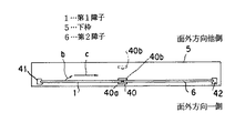
【図1】 本発明の実施の形態を示す引戸の概略正面図である。
【図2】 第1障子と第2障子の開閉動作を示す概略横断面図である。
【図3】 図1のE−E詳細断面図である。
【図4】 障子支持具の平面図である。
【図5】 上枠の一部破断詳細正面図である。
【図6】 図5のF−F断面図である。
【図7】 障子の開閉動作の詳細説明図である。
【符号の説明】
1…第1障子
2…第1戸車
4…上枠
5…下枠
6…第2障子
7…第2戸車
10…第1レール
11…第2レール
50…第1補助レール
54…補助レール部
55…案内部材
60…第2補助レール[0001]
BACKGROUND OF THE INVENTION
The present invention relates to a sliding door that opens and closes by moving a shoji along an upper frame and a lower frame.
[0002]
[Prior art]
A sliding door as disclosed in Japanese Patent Application Laid-Open No. 8-121014 has been proposed.
This sliding door has a first rail and a second rail on the upper part on both sides in the out-of-plane direction, an upper frame having a third rail on a lower part on one side in the out-of-plane direction, straddling the first rail and the second rail, and in-plane An axle that moves in a direction, a first shoji that moves in an out-of-plane direction along the axle, and a second shoji that moves in an in-plane direction along the third rail, and the first and second shoji By moving to the closed position and moving the first shoji in the out-of-plane direction, the first shoji and the second shoji can be flush with the out-of-plane direction at the closed position.
[0003]
[Problems to be solved by the invention]
In the case of the aforementioned sliding door, when the first shoji is moved in an in-plane direction or when the first shoji is in the open position, if the first shoji is moved in the out-of-plane direction along the axle, the first shoji The second shoji may collide.
[0004]
Then, an object of this invention is to provide the sliding door which enabled it to solve the above-mentioned subject.
[0005]
[Means for Solving the Problems]
The present invention includes an upper frame provided with a first rail on the other side in the out-of-plane direction and a second rail on one side in the out-of-plane direction;
A first shoji that moves in the in-plane direction along the first rail over a closed position and an open position;
A second shoji that moves in the in-plane direction along the second rail over the closed position and the open position;
A first auxiliary rail attached to the upper frame and having an auxiliary rail portion oblique to the out-of-plane direction connecting the first rail and the second rail;
A second auxiliary rail that is attached to the upper frame and has an auxiliary rail portion that is inclined in an out-of-plane direction connecting the first rail and the second rail;
The first shoji is close to the closed position, and one side in the in-plane direction and the other side in the out-of-plane direction of the first shoji are along the auxiliary rail of the first auxiliary rail and the auxiliary rail of the second auxiliary rail. And the first shoji is moved to the closed position along the second rail, being guided obliquely across the first rail and the second rail,
The first auxiliary rail is provided with a guide member, and the guide member is held in a state in which the auxiliary rail portion is closed with an elastic material and the second shoji is allowed to move along the second rail toward the open position. When the one side part in the in-plane direction of the first shoji moves from the first rail to the second rail, the guide member swings to open the auxiliary rail part, and one side part in the in-plane direction of the first shoji The sliding door is characterized in that it is in a state of preventing movement along the second rail toward the open position.
[0006]
[Action]
According to the present invention, when the first shoji moves along the first rail from the open position toward the close position and becomes close to the close position, the first shoji is moved along the auxiliary rail portions of the first and second auxiliary rails. One side part in the in-plane direction and the other side part in the in-plane direction move toward one side in the out-of-plane direction and move to the second rail , and the first and second shojis are substantially identical in the out-of-plane direction at the closed position. Position.
Thereby, when the sliding door is closed, there is no step in the out-of-plane direction between the first shoji and the second shoji, so the appearance is good.
[0007]
When the first shoji moves between the close position and the open position, it moves along the first rail, and the first shoji moves in the in-plane direction along the first rail without moving in the out-of-plane direction. .
Further, the guide member prevents the first shoji from moving from the closed position along the second rail toward the open position.
Thus, there is no risk of accidentally colliding with the second shoji when the first shoji is opened and closed.
[0008]
Moreover, since the guide member allows the second shoji to move toward the open position, the second shoji can be moved along the second rail between the closed position and the open position.
[0009]
DETAILED DESCRIPTION OF THE INVENTION
As shown in FIG. 1, the first shoji 1 is suspended and supported by the
The
The
[0010]
As shown in FIG. 2, the summoning
[0011]
The first door stopper part
The second door stopper
[0012]
Next, the specific shape of each member will be described.
As shown in FIG. 3, the
[0013]
The
A pair of
The
[0014]
As shown in FIGS. 3 and 4, the one side support 40 a of the summoning
The other side support
The connecting
[0015]
Since it is like this, by inserting a key into the
From the above-mentioned state, the
[0016]
As shown in FIG. 4, the first door-contact part
In addition, the recessed part 41a of the 1st door part part
[0017]
Next, the structure of a portion where the first shoji 1 is moved obliquely in the out-of-plane direction near the closed position will be described.
As shown in FIG. 1, when the first shoji 1 in the
[0018]
The first
The
The
The
The
[0019]
Since it is like this, the wheel 26 (one side in the in-plane direction of the first shoji 1) of the
[0020]
A
The
[0021]
As shown in FIGS. 5 and 6, the second
The second
The other end 64a in the out-of-plane direction of the
[0022]
As such, the
[0023]
The
[0024]
Next, the opening / closing operation of the shoji will be described.
As shown in FIG. 7A, when the first shoji 1 and the
Accordingly, the first shoji 1 and the
The
[0025]
When the first shoji 1 is moved from the above-described state toward the open position, one
At this time, the
When the first shoji 1 moves to the
[0026]
When the
Thereby, the
[0027]
The sliding door of the above-mentioned embodiment is used in such a way that an intermediate air layer is formed between the curtain wall and the window portion, and air is circulated through the intermediate air layer to ventilate the room. Is done. Of course, it can be used other than this.
[0028]
【The invention's effect】
According to the first aspect of the present invention, when the first shoji moves along the first rail from the open position toward the closed position and approaches the closed position , the first shoji is moved along the auxiliary rail portions of the first and second auxiliary rails. The one side in the in-plane direction and the other side in the in-plane direction move toward one side in the out-of-plane direction and move to the second rail , and the first and second shoji are out-of-plane at the closed position. It becomes substantially the same position in the direction.
Thereby, when the sliding door is closed, there is no step in the out-of-plane direction between the first shoji and the second shoji, so the appearance is good.
[0029]
When the first shoji moves between the close position and the open position, it moves along the first rail, and the first shoji moves in the in-plane direction along the first rail without moving in the out-of-plane direction. .
Further, the guide member prevents the first shoji from moving from the closed position along the second rail toward the open position.
Thus, there is no risk of accidentally colliding with the second shoji when the first shoji is opened and closed.
[0030]
Moreover, since the guide member allows the second shoji to move toward the open position, the second shoji can be moved along the second rail between the closed position and the open position.
[Brief description of the drawings]
FIG. 1 is a schematic front view of a sliding door showing an embodiment of the present invention.
FIG. 2 is a schematic cross-sectional view showing opening and closing operations of a first shoji and a second shoji.
FIG. 3 is a detailed cross-sectional view taken along the line EE of FIG.
FIG. 4 is a plan view of a shoji support.
FIG. 5 is a detailed front view of a partially broken upper frame.
6 is a cross-sectional view taken along line FF in FIG.
FIG. 7 is a detailed explanatory diagram of a shoji opening / closing operation.
[Explanation of symbols]
DESCRIPTION OF SYMBOLS 1 ...
Claims (1)
前記第1レールに沿って閉じ位置と開き位置に亘って面内方向に移動する第1障子と、
前記第2レールに沿って閉じ位置と開き位置に亘って面内方向に移動する第2障子と、
前記上枠に取付けられ、前記第1レールと第2レールを連続する面外方向に斜めの補助レール部を有した第1補助レールと、
前記上枠に取付けられ、前記第1レールと第2レールを連続する面外方向に斜めの補助レール部を有した第2補助レールを備え、
前記第1障子が閉じ位置近くで、その第1障子の面内方向一側部、面外方向他側部が、前記第1補助レールの補助レール部、第2補助レールの補助レール部に沿って第1レールと第2レールに亘ってそれぞれ斜めにガイドされて第1障子は第2レールに沿って閉じ位置に移動し、
前記第1補助レールに案内部材を設け、この案内部材は、弾性材で補助レール部を閉じ、かつ第2障子が第2レールに沿って開き位置に向けて移動することを許容する状態に保持され、第1障子の面内方向一側部が第1レールから第2レールに移動することで案内部材が揺動して補助レール部を開放し、かつ第1障子の面内方向一側部が第2レールに沿って開き位置に向けて移動することを阻止する状態となることを特徴とする引戸。 An upper frame having a first rail on the other side in the out-of-plane direction and a second rail on one side in the out-of-plane direction;
A first shoji that moves in the in-plane direction along the first rail over a closed position and an open position;
A second shoji that moves in the in-plane direction along the second rail over a closed position and an open position;
A first auxiliary rail attached to the upper frame and having an auxiliary rail portion oblique to the out-of-plane direction connecting the first rail and the second rail;
A second auxiliary rail attached to the upper frame and having an auxiliary rail portion oblique to the out-of-plane direction connecting the first rail and the second rail;
The first shoji is close to the closed position, and the in-plane direction one side portion and the out-of-plane direction other side portion of the first shoji are along the auxiliary rail portion of the first auxiliary rail and the auxiliary rail portion of the second auxiliary rail. The first shoji is moved to the closed position along the second rail, being guided obliquely across the first rail and the second rail,
A guide member is provided on the first auxiliary rail, and the guide member is held in a state in which the auxiliary rail portion is closed with an elastic material and the second shoji is allowed to move along the second rail toward the open position. When the one side part in the in-plane direction of the first shoji moves from the first rail to the second rail, the guide member swings to open the auxiliary rail part, and one side part in the in-plane direction of the first shoji The sliding door is in a state in which it is prevented from moving toward the open position along the second rail.
Priority Applications (1)
| Application Number | Priority Date | Filing Date | Title |
|---|---|---|---|
| JP2000336270A JP3713661B2 (en) | 2000-11-02 | 2000-11-02 | sliding door |
Applications Claiming Priority (1)
| Application Number | Priority Date | Filing Date | Title |
|---|---|---|---|
| JP2000336270A JP3713661B2 (en) | 2000-11-02 | 2000-11-02 | sliding door |
Publications (2)
| Publication Number | Publication Date |
|---|---|
| JP2002138740A JP2002138740A (en) | 2002-05-17 |
| JP3713661B2 true JP3713661B2 (en) | 2005-11-09 |
Family
ID=18811873
Family Applications (1)
| Application Number | Title | Priority Date | Filing Date |
|---|---|---|---|
| JP2000336270A Expired - Fee Related JP3713661B2 (en) | 2000-11-02 | 2000-11-02 | sliding door |
Country Status (1)
| Country | Link |
|---|---|
| JP (1) | JP3713661B2 (en) |
Families Citing this family (3)
| Publication number | Priority date | Publication date | Assignee | Title |
|---|---|---|---|---|
| JP2009019466A (en) * | 2007-07-13 | 2009-01-29 | Best:Kk | Flat sliding door |
| JP5717132B2 (en) * | 2011-02-04 | 2015-05-13 | Ykk Ap株式会社 | Shoji's upper summoning member |
| JP2020105831A (en) * | 2018-12-27 | 2020-07-09 | パナソニックIpマネジメント株式会社 | Sliding door device |
-
2000
- 2000-11-02 JP JP2000336270A patent/JP3713661B2/en not_active Expired - Fee Related
Also Published As
| Publication number | Publication date |
|---|---|
| JP2002138740A (en) | 2002-05-17 |
Similar Documents
| Publication | Publication Date | Title |
|---|---|---|
| JP2002339646A (en) | Lock device for locking traveling device guided by rail | |
| KR101077227B1 (en) | Caster having a function of automatically opening and closing | |
| JP4130020B2 (en) | Elevator control panel opening and closing device | |
| KR20100001473A (en) | Chassis for windows and doors having hidden type rail | |
| US5001861A (en) | Automatic universal deadbolt locking device | |
| JP3713661B2 (en) | sliding door | |
| WO2006014164A3 (en) | Electromagnetically operated elevator door lock | |
| JPH02267023A (en) | Slider link of car door glass | |
| JPS6120940Y2 (en) | ||
| JP4169905B2 (en) | Sliding door sickle lock device | |
| JPH1171081A (en) | Entrance for elevator | |
| JP4693233B2 (en) | Elevator sliding door device | |
| JP4093421B2 (en) | Four-story sliding sash | |
| JP7186611B2 (en) | evacuation door | |
| CN113966309B (en) | Elevator door | |
| JPH0524869U (en) | Lower guide device for sliding doors | |
| JP4606609B2 (en) | Elevator doorway device | |
| KR101896961B1 (en) | Window structure | |
| JP2005351080A (en) | Clearance closing device | |
| JP2002038819A (en) | Interlocking sliding door | |
| JP3256433B2 (en) | Sliding door structure | |
| JPS62387Y2 (en) | ||
| JPH0680364A (en) | Elevator | |
| KR200341293Y1 (en) | Open and shut crime prevention door | |
| JP2001240350A (en) | Car door lock device of elevator |
Legal Events
| Date | Code | Title | Description |
|---|---|---|---|
| A977 | Report on retrieval |
Free format text: JAPANESE INTERMEDIATE CODE: A971007 Effective date: 20041213 |
|
| A131 | Notification of reasons for refusal |
Free format text: JAPANESE INTERMEDIATE CODE: A131 Effective date: 20041222 |
|
| A521 | Written amendment |
Free format text: JAPANESE INTERMEDIATE CODE: A523 Effective date: 20050221 |
|
| A131 | Notification of reasons for refusal |
Free format text: JAPANESE INTERMEDIATE CODE: A131 Effective date: 20050406 |
|
| A521 | Written amendment |
Free format text: JAPANESE INTERMEDIATE CODE: A523 Effective date: 20050606 |
|
| TRDD | Decision of grant or rejection written | ||
| A01 | Written decision to grant a patent or to grant a registration (utility model) |
Free format text: JAPANESE INTERMEDIATE CODE: A01 Effective date: 20050810 |
|
| A61 | First payment of annual fees (during grant procedure) |
Free format text: JAPANESE INTERMEDIATE CODE: A61 Effective date: 20050811 |
|
| R150 | Certificate of patent or registration of utility model |
Free format text: JAPANESE INTERMEDIATE CODE: R150 |
|
| FPAY | Renewal fee payment (event date is renewal date of database) |
Free format text: PAYMENT UNTIL: 20090902 Year of fee payment: 4 |
|
| FPAY | Renewal fee payment (event date is renewal date of database) |
Free format text: PAYMENT UNTIL: 20100902 Year of fee payment: 5 |
|
| FPAY | Renewal fee payment (event date is renewal date of database) |
Free format text: PAYMENT UNTIL: 20100902 Year of fee payment: 5 |
|
| FPAY | Renewal fee payment (event date is renewal date of database) |
Free format text: PAYMENT UNTIL: 20110902 Year of fee payment: 6 |
|
| FPAY | Renewal fee payment (event date is renewal date of database) |
Free format text: PAYMENT UNTIL: 20110902 Year of fee payment: 6 |
|
| FPAY | Renewal fee payment (event date is renewal date of database) |
Free format text: PAYMENT UNTIL: 20120902 Year of fee payment: 7 |
|
| FPAY | Renewal fee payment (event date is renewal date of database) |
Free format text: PAYMENT UNTIL: 20130902 Year of fee payment: 8 |
|
| LAPS | Cancellation because of no payment of annual fees |