JP3712036B2 - Salt water desalination equipment - Google Patents
Salt water desalination equipment Download PDFInfo
- Publication number
- JP3712036B2 JP3712036B2 JP13859199A JP13859199A JP3712036B2 JP 3712036 B2 JP3712036 B2 JP 3712036B2 JP 13859199 A JP13859199 A JP 13859199A JP 13859199 A JP13859199 A JP 13859199A JP 3712036 B2 JP3712036 B2 JP 3712036B2
- Authority
- JP
- Japan
- Prior art keywords
- salt water
- heat collector
- solar heat
- gas
- pipe
- Prior art date
- Legal status (The legal status is an assumption and is not a legal conclusion. Google has not performed a legal analysis and makes no representation as to the accuracy of the status listed.)
- Expired - Fee Related
Links
Images


Classifications
-
- Y—GENERAL TAGGING OF NEW TECHNOLOGICAL DEVELOPMENTS; GENERAL TAGGING OF CROSS-SECTIONAL TECHNOLOGIES SPANNING OVER SEVERAL SECTIONS OF THE IPC; TECHNICAL SUBJECTS COVERED BY FORMER USPC CROSS-REFERENCE ART COLLECTIONS [XRACs] AND DIGESTS
- Y02—TECHNOLOGIES OR APPLICATIONS FOR MITIGATION OR ADAPTATION AGAINST CLIMATE CHANGE
- Y02A—TECHNOLOGIES FOR ADAPTATION TO CLIMATE CHANGE
- Y02A20/00—Water conservation; Efficient water supply; Efficient water use
- Y02A20/124—Water desalination
- Y02A20/138—Water desalination using renewable energy
- Y02A20/142—Solar thermal; Photovoltaics
-
- Y—GENERAL TAGGING OF NEW TECHNOLOGICAL DEVELOPMENTS; GENERAL TAGGING OF CROSS-SECTIONAL TECHNOLOGIES SPANNING OVER SEVERAL SECTIONS OF THE IPC; TECHNICAL SUBJECTS COVERED BY FORMER USPC CROSS-REFERENCE ART COLLECTIONS [XRACs] AND DIGESTS
- Y02—TECHNOLOGIES OR APPLICATIONS FOR MITIGATION OR ADAPTATION AGAINST CLIMATE CHANGE
- Y02A—TECHNOLOGIES FOR ADAPTATION TO CLIMATE CHANGE
- Y02A20/00—Water conservation; Efficient water supply; Efficient water use
- Y02A20/20—Controlling water pollution; Waste water treatment
- Y02A20/208—Off-grid powered water treatment
- Y02A20/212—Solar-powered wastewater sewage treatment, e.g. spray evaporation
-
- Y—GENERAL TAGGING OF NEW TECHNOLOGICAL DEVELOPMENTS; GENERAL TAGGING OF CROSS-SECTIONAL TECHNOLOGIES SPANNING OVER SEVERAL SECTIONS OF THE IPC; TECHNICAL SUBJECTS COVERED BY FORMER USPC CROSS-REFERENCE ART COLLECTIONS [XRACs] AND DIGESTS
- Y02—TECHNOLOGIES OR APPLICATIONS FOR MITIGATION OR ADAPTATION AGAINST CLIMATE CHANGE
- Y02E—REDUCTION OF GREENHOUSE GAS [GHG] EMISSIONS, RELATED TO ENERGY GENERATION, TRANSMISSION OR DISTRIBUTION
- Y02E10/00—Energy generation through renewable energy sources
- Y02E10/40—Solar thermal energy, e.g. solar towers
- Y02E10/44—Heat exchange systems
Description
【0001】
【発明の属する技術分野】
本発明は、塩水淡水化装置に係り、特に、太陽熱によって、海水等から淡水を得る塩水淡水化装置に関するものである。
【0002】
【従来の技術】
従来、海水等の塩分を含んだ水を加熱し、水分を蒸発させ、その水蒸気を凝縮させることで、塩分を含まない水である淡水を得る塩水淡水化装置はよく知られた装置である。該装置は、通常、発生した蒸気を用いて、低圧部の塩水を順次加熱蒸発させる、所謂、多重効用とすることが多い。
前記塩水淡水化装置に用いる電気としては、真空発生装置(真空ポンプ、又は水ジェットポンプ)、濃塩水排出ポンプ及び淡水取出ポンプ等のモーターや、切替弁駆動モーターなどの小容量モーター類の駆動用電源と制御用電源とが必要であり、使用する電力量が多くなるという問題点があった。
【0003】
【発明が解決しようとする課題】
本発明は、上記従来技術に鑑み、消費電力を極端に減らし、太陽電池単独、あるいは太陽電池と蓄電池とで駆動し、外部電力を不要とする太陽熱利用の塩水淡水化装置を提供することを課題とする。
【0004】
【課題を解決するための手段】
上記課題を解決するために、本発明では、塩水タンク、太陽熱集熱器、気液分離器、蒸発濃縮器、凝縮器を主要構成機器として、これらを塩水経路及び水・蒸気経路で接続し、太陽熱集熱器からの熱を熱源として、塩水を加熱蒸発させて淡水を作る多重効用型塩水淡水化装置において、前記太陽熱集熱器と前記気液分離器とで蒸発濃縮器を構成し、該太陽熱集熱器の上部と該気液分離器の上部とを配管で連結し、該太陽熱集熱器の下部と該気液分離器の下部とを配管で連結し、該太陽熱集熱器の下部と気液分離器下部とを結ぶ前記配管と、前記塩水タンクとを配管で連結し、前記太陽熱集熱器の上部と、前記塩水タンクを配管で連結し、該塩水タンク内に凝縮器を設けたことを特徴とする多重効用型塩水淡水化装置としたものである。
また、本発明では、塩水タンク、太陽熱集熱器、気液分離器、蒸発濃縮器、凝縮器を主要構成機器として、これらを塩水経路及び水・蒸気経路で接続し、太陽熱集熱器からの熱を熱源として、塩水を加熱蒸発させて淡水を作る多重効用型塩水淡水化装置において、前記太陽熱集熱器と気液分離器とで第1段目の蒸発濃縮器を構成し、該太陽熱集熱器は、水平面から傾斜させて設置され、その上部と気液分離器の上部空間とを配管で結び、その下部と気液分離器の下部とを配管で連結し、また、該太陽熱集熱器下部と気液分離器下部とを結ぶ配管と、前記塩水タンクの下部とを配管で連結し、前記太陽熱集熱器の上部と、塩水タンクの液を有する上部位置とを配管で連結し、該塩水タンクには、レベルスイッチを設け、塩水液面を所定のレベルに保つ制御手段を有すると共に、該塩水タンク内に凝縮器用熱交換器を設けることとしたものである。
【0005】
前記多重効用型塩水淡水化装置において、太陽熱集熱器の上部と、気液分離器又は塩水タンク上部とを結ぶ配管、及び太陽熱集熱器下部と、塩水タンク又は気液分離器下部とを結ぶ配管には、それぞれ弁を設け、選択的に液を連通させるようにすることができる。
また、前記塩水タンクの液面を所定のレベルに保つ制御手段は、外部からの塩水供給を制御して行うことができ、太陽熱集熱器の上部と塩水タンクとを連結する配管の該塩水タンクの上部位置は、前記の所定の液面レベルよりは下である。
【0006】
【発明の実施の形態】
本発明は、蓄熱タンク内の蓄熱剤として塩水を用い、該タンク内に塩水淡水化装置の凝縮器用熱交換器を設け、夜間に天空放射により集熱器を冷却させ、集熱器と蓄熱タンクとを結んで、塩水を循環させて、蓄熱タンク内の塩水を冷却することに特徴を有する。
次に、図面を用いて、本発明を詳細に説明する。
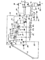
図1〜4は、本発明の塩水淡水化装置のフロー構成図を示し、図1は淡水化運転、図2は夜間冷却運転、図3及び図4は塩水淡水化装置の別の構成を示すフロー構成図である。
図において、1は塩水タンク、2A、2B、2Cは予熱器、3は太陽熱集熱器、4は気液分離器、5、6、7は蒸発濃縮器、8は濃塩水タンク、9は凝縮器、10は淡水タンク、11は液面センサーを示す。
【0007】
まず、図1を用いて塩水淡水化運転を説明する。
図1は、四重効用として示しており、外部からの塩水aを塩水タンク1に管21から入れ、凝縮器9の冷却に利用する。塩水タンク1の塩水aは、大気圧と塩水淡水化装置の内圧の差により、管22を通り装置内に吸入されて行く。予熱器2A、2B、2Cで各蒸発濃縮器7、6、5からの蒸気で加熱された後、第1段目の蒸発濃縮器としての太陽熱集熱器3に入る。
集熱器3で加熱され、沸騰しながら集熱器出口にある気液分離器4に入る。発生した蒸気は管31を通り、第2段目の蒸発濃縮器5の熱交換器に入り、熱交換器外側の塩水を加熱し、一部液化し、予熱器2Cに入り、供給塩水を加熱して液化し、下段の予熱器2Bに入る。一方、第1段目で濃縮された塩水は、管26から第2段目の蒸発濃縮器5に入り、前述の管31からの発生蒸気で加熱され、蒸発濃縮される。
【0008】
第2段目の蒸発濃縮器5で発生した蒸気は、管32から第3段目の蒸発濃縮器6の熱交換器に入り、また第3段目の蒸発濃縮器6で発生した蒸気は、管33から第4段目の蒸発濃縮器7の熱交換器に入って同様の蒸発濃縮を行う。また第2段目で濃縮された塩水は、管27から第3段目の蒸発濃縮器6に入り、第3段目で濃縮された塩水は、管28から第4段目の蒸発濃縮器7に入り、蒸発濃縮され、管29から濃塩水タンク8に入る。濃塩水bは液面センサー等の信号を基にポンプ19により断続的に排出される。
第4段目の蒸発濃縮器7で発生した蒸気は、管34から凝縮器9に入り、冷却されて液化し、一方、第4段目の蒸発濃縮器を加熱した蒸気は、管33から予熱器2Aに入り、液化し、管35から凝縮器9に入り、管36より淡水タンク10に貯えられ、貯えられた水cは、液面センサー等の信号を基に、ポンプ20により断続的に排出される。
【0009】
塩水a中に含まれていた溶存気体は、蒸発濃縮器で放出され、蒸気系を通して、最終的には、凝縮器9に集まってくる。凝縮器9から、真空装置37にてこの気体を排出する。
塩水タンク1内の塩水aは、凝縮器9を冷却し、自らは加熱されて、上昇流となって、自然対流を起こす。凝縮器9はこのため、塩水タンク1内の下部に設けるのが好ましい。太陽熱が確保できる間は、淡水化運転が可能であり、この間、凝縮熱が塩水タンクに放出される。塩水タンク容量はこの温度上昇を考慮して決める。なお、淡水化運転中であっても、塩水タンク1は外側から外気で冷却されている。しかし、凝縮熱の方が多いので温度は上昇する。
このような塩水淡水化運転においては、弁13が閉、弁12、14が開となり、弁15〜18は制御されている。
【0010】
このように太陽熱集熱器で、塩水aは加熱され、一部蒸気となって、気液分離器4に入る。蒸気は、塩水淡水化装置の第2段目の蒸発濃縮器5の熱交換器に入る。分離された塩水の一部は、第2段目の蒸発濃縮器5に行き、残りは太陽熱集熱器3の下部に導かれ、予熱器2Cからの塩水とともに集熱器3に入る。
集熱器3での蒸気発生が気泡ポンプの役目をし、気液分離器4からの塩水は自然循環が可能である。
なお、破線で示したように、循環ポンプ38を用い、強制循環も当然可能であり、この場合、ポンプは太陽電池で駆動するのも良い。
【0011】
図2は、塩水タンクを冷却する夜間冷却運転を示す。
太陽熱による塩水淡水化で、塩水タンク1内の塩水は温度上昇している。
夜間は、気液分離器4を弁12、14で仕切り、集熱器3と塩水タンク1との間に塩水の循環経路を設ける。塩水タンク1上部の塩水が管25から弁13を通って集熱器3上部に入り、集熱器3で夜間の冷気及び天空放射により冷却され、集熱器3内を下降し、管23、弁15、管22を通り、塩水タンク1下部に入る。循環は、温度差による自然循環が可能である。
この夜間運転では、弁13と15は全開で、弁12、14、16、17、18は閉である。
【0012】
図3は、本発明の塩水淡水化装置の別の構成を示すフロー構成図であり、図3では、塩水タンク1の上部空間部に真空装置37の配管が接続されると共に、この空間部と太陽熱集熱器3の上部とを配管30で結んでいる。
図3では、塩水タンク1を減圧して、塩水から溶存気体を放出させる。この場合、塩水タンク1の圧力によっては、塩水aを淡水化装置に供給するのにポンプ39が必要になる。
夜間冷却中、塩水タンク1上部と集熱器3上部を弁40を開として連通させると、塩水が落下し、冷却を完了させることができる。
図4は、図3と同様に塩水タンク1を減圧して、塩水aから溶存気体を放出させた例であり、図3との相違は、管30がない点にある。また、夜間の冷却に際しては、ポンプ41を設けて強制循環させることができる。
【0013】
【発明の効果】
本発明によれば、塩水の循環を自然循環とすることができるので、消費電力を極端に減らし、太陽電池単独、あるいは太陽電池と蓄電池で駆動し、外部電力を不要とすることができる塩水淡水化装置とすることができた。
【図面の簡単な説明】
【図1】本発明の塩水淡水化装置の淡水化運転を説明するフロー構成図。
【図2】本発明の塩水淡水化装置の夜間冷却運転を説明するフロー構成図。
【図3】本発明の塩水淡水化装置の別の構成を説明するフロー構成図。
【図4】本発明の塩水淡水化装置の別の構成を説明するフロー構成図。
【符号の説明】
1:塩水タンク、2A、2B、2C:予熱器、3:太陽熱集熱器、4:気液分離器、5、6、7:蒸発濃縮器、8:濃塩水タンク、9:凝縮器、10:淡水タンク、11:液面センサー[0001]
BACKGROUND OF THE INVENTION
The present invention relates to a salt water desalination apparatus, and more particularly to a salt water desalination apparatus that obtains fresh water from seawater or the like by solar heat.
[0002]
[Prior art]
2. Description of the Related Art Conventionally, a salt water desalination apparatus that obtains fresh water that is water that does not contain salt by heating water containing salt such as seawater, evaporating water, and condensing the water vapor is a well-known device. The apparatus usually has a so-called multiple effect, in which the generated steam is used to sequentially heat and evaporate the salt water in the low-pressure part.
Electricity used in the salt water desalination apparatus is for driving motors such as vacuum generators (vacuum pumps or water jet pumps), concentrated salt water discharge pumps and fresh water extraction pumps, and small capacity motors such as switching valve drive motors. A power supply and a control power supply are necessary, and there is a problem that the amount of power used increases.
[0003]
[Problems to be solved by the invention]
SUMMARY OF THE INVENTION In view of the above prior art, the present invention provides a solar water-based salt water desalination apparatus that drastically reduces power consumption, is driven by a solar cell alone or by a solar cell and a storage battery, and does not require external power. And
[0004]
[Means for Solving the Problems]
In order to solve the above problems, in the present invention, a salt water tank, a solar heat collector, a gas-liquid separator, an evaporative concentrator, and a condenser are used as main components, and these are connected by a salt water path and a water / steam path, In the multi-effect salt water desalination apparatus that produces fresh water by heating and evaporating salt water using heat from the solar heat collector as a heat source, the solar heat collector and the gas-liquid separator constitute an evaporation concentrator, The upper part of the solar heat collector and the upper part of the gas-liquid separator are connected by a pipe, the lower part of the solar heat collector and the lower part of the gas-liquid separator are connected by a pipe, and the lower part of the solar heat collector The pipe connecting the pipe and the lower part of the gas-liquid separator and the salt water tank are connected by a pipe, the upper part of the solar heat collector and the salt water tank are connected by a pipe, and a condenser is provided in the salt water tank This is a multi-effect salt water desalination apparatus characterized by the above.
In the present invention, a salt water tank, a solar heat collector, a gas-liquid separator, an evaporative concentrator, and a condenser are used as main components, and these are connected by a salt water path and a water / steam path, In a multi-effect salt water desalination apparatus that heats and evaporates salt water to produce fresh water using heat as a heat source, the solar heat collector and the gas-liquid separator constitute a first stage evaporative concentrator, and the solar heat collection The heater is installed to be inclined from a horizontal plane, the upper part thereof is connected to the upper space of the gas-liquid separator by a pipe, the lower part thereof is connected to the lower part of the gas-liquid separator by a pipe, and the solar heat collecting A pipe connecting the lower part of the vessel and the lower part of the gas-liquid separator, and a lower part of the salt water tank are connected by a pipe, and the upper part of the solar heat collector and the upper part having the liquid of the salt water tank are connected by a pipe, The salt water tank is provided with a level switch, and the salt water level is set to a predetermined level. Which has a control means for maintaining, in which was the provision of the condenser heat exchanger in said brine tank.
[0005]
In the multi-effect salt water desalination apparatus, a pipe connecting the upper part of the solar heat collector and the upper part of the gas-liquid separator or the salt water tank, and a lower part of the solar heat collector and the lower part of the salt water tank or the gas-liquid separator. Each pipe can be provided with a valve so that the liquid can be selectively communicated therewith.
Further, the control means for maintaining the liquid level of the salt water tank at a predetermined level can be performed by controlling the supply of salt water from the outside, and the salt water tank of the pipe connecting the upper part of the solar heat collector and the salt water tank The upper position is lower than the predetermined liquid level.
[0006]
DETAILED DESCRIPTION OF THE INVENTION
The present invention uses salt water as a heat storage agent in a heat storage tank, a heat exchanger for a condenser of a salt water desalination apparatus is provided in the tank, the heat collector is cooled by sky radiation at night, and the heat collector and the heat storage tank And the salt water is circulated to cool the salt water in the heat storage tank.
Next, the present invention will be described in detail with reference to the drawings.
1-4 shows the flow block diagram of the salt water desalination apparatus of this invention, FIG. 1 shows desalination operation, FIG. 2 shows nighttime cooling operation, FIG.3 and FIG.4 shows another structure of a salt water desalination apparatus. It is a flow block diagram.
In the figure, 1 is a salt water tank, 2A, 2B and 2C are preheaters, 3 is a solar heat collector, 4 is a gas-liquid separator, 5, 6 and 7 are evaporative concentrators, 8 is a concentrated salt water tank, and 9 is condensed. 10 is a fresh water tank, and 11 is a liquid level sensor.
[0007]
First, the salt water desalination operation will be described with reference to FIG.
FIG. 1 shows a quadruple effect, and salt water a from the outside is put into a
It is heated by the
[0008]
The steam generated in the second stage
The steam generated in the fourth stage
[0009]
The dissolved gas contained in the salt water a is discharged by the evaporation concentrator, and finally gathers in the
The salt water a in the
In such a saltwater desalination operation, the
[0010]
In this way, the salt water a is heated by the solar heat collector, and partially enters the gas-liquid separator 4 as steam. The steam enters the heat exchanger of the
Steam generation in the
In addition, as shown with the broken line, the
[0011]
FIG. 2 shows a night-time cooling operation for cooling the salt water tank.
Due to the desalination of salt water by solar heat, the temperature of the salt water in the
At night, the gas-liquid separator 4 is partitioned by
In this nighttime operation, the
[0012]
FIG. 3 is a flow configuration diagram showing another configuration of the salt water desalination apparatus of the present invention. In FIG. 3, the piping of the
In FIG. 3, the
If the
FIG. 4 shows an example in which the
[0013]
【The invention's effect】
According to the present invention, since salt water circulation can be natural circulation, salt water fresh water that can reduce power consumption drastically and can be driven by a solar cell alone or by a solar cell and a storage battery, eliminating the need for external power. It was possible to make it a device.
[Brief description of the drawings]
FIG. 1 is a flow diagram illustrating a desalination operation of a salt water desalination apparatus according to the present invention.
FIG. 2 is a flow diagram illustrating nighttime cooling operation of the salt water desalination apparatus of the present invention.
FIG. 3 is a flow configuration diagram illustrating another configuration of the salt water desalination apparatus of the present invention.
FIG. 4 is a flow configuration diagram illustrating another configuration of the salt water desalination apparatus of the present invention.
[Explanation of symbols]
1: salt water tank, 2A, 2B, 2C: preheater, 3: solar heat collector, 4: gas-liquid separator, 5, 6, 7: evaporative concentrator, 8: concentrated salt water tank, 9: condenser, 10 : Fresh water tank, 11: Liquid level sensor
Claims (3)
Priority Applications (1)
| Application Number | Priority Date | Filing Date | Title |
|---|---|---|---|
| JP13859199A JP3712036B2 (en) | 1999-05-19 | 1999-05-19 | Salt water desalination equipment |
Applications Claiming Priority (1)
| Application Number | Priority Date | Filing Date | Title |
|---|---|---|---|
| JP13859199A JP3712036B2 (en) | 1999-05-19 | 1999-05-19 | Salt water desalination equipment |
Publications (3)
| Publication Number | Publication Date |
|---|---|
| JP2000325941A JP2000325941A (en) | 2000-11-28 |
| JP2000325941A5 JP2000325941A5 (en) | 2005-05-19 |
| JP3712036B2 true JP3712036B2 (en) | 2005-11-02 |
Family
ID=15225688
Family Applications (1)
| Application Number | Title | Priority Date | Filing Date |
|---|---|---|---|
| JP13859199A Expired - Fee Related JP3712036B2 (en) | 1999-05-19 | 1999-05-19 | Salt water desalination equipment |
Country Status (1)
| Country | Link |
|---|---|
| JP (1) | JP3712036B2 (en) |
Cited By (1)
| Publication number | Priority date | Publication date | Assignee | Title |
|---|---|---|---|---|
| CN102976421A (en) * | 2012-11-22 | 2013-03-20 | 中国神华能源股份有限公司 | Sea water desalination system |
Families Citing this family (4)
| Publication number | Priority date | Publication date | Assignee | Title |
|---|---|---|---|---|
| KR101632252B1 (en) * | 2010-04-30 | 2016-06-21 | 하루오 우에하라 | Pure liquid production device |
| CN102863035A (en) * | 2011-07-07 | 2013-01-09 | 常州化工设备有限公司 | Multi-effect evaporating and desalting device desalting process |
| CN102923800B (en) * | 2012-11-06 | 2014-03-26 | 集美大学 | Heat accumulating type seawater desalination device and method of seawater desalination |
| CN102992426A (en) * | 2012-12-12 | 2013-03-27 | 众和海水淡化工程有限公司 | Small and simple seawater desalination device |
-
1999
- 1999-05-19 JP JP13859199A patent/JP3712036B2/en not_active Expired - Fee Related
Cited By (2)
| Publication number | Priority date | Publication date | Assignee | Title |
|---|---|---|---|---|
| CN102976421A (en) * | 2012-11-22 | 2013-03-20 | 中国神华能源股份有限公司 | Sea water desalination system |
| CN102976421B (en) * | 2012-11-22 | 2014-07-09 | 中国神华能源股份有限公司 | Sea water desalination system |
Also Published As
| Publication number | Publication date |
|---|---|
| JP2000325941A (en) | 2000-11-28 |
Similar Documents
| Publication | Publication Date | Title |
|---|---|---|
| US5816070A (en) | Enhanced lithium bromide absorption cycle water vapor recompression absorber | |
| US4302297A (en) | Desalination apparatus with power generation | |
| US6919000B2 (en) | Diffusion driven desalination apparatus and process | |
| AU618509B2 (en) | Absorption refrigeration method and apparatus | |
| US7225620B2 (en) | Diffusion driven water purification apparatus and process | |
| US6010599A (en) | Compact vacuum distillation device | |
| US4304577A (en) | Water producing apparatus | |
| JPH07508926A (en) | water distillation equipment | |
| CN103550941B (en) | Low-temperature evaporation and concentration device and high-concentration waste water concentration method | |
| CN108203129A (en) | Heat pump driven injection type negative pressure desalination plant and method | |
| US6260370B1 (en) | Solar refrigeration and heating system usable with alternative heat sources | |
| JP4139597B2 (en) | Desalination equipment | |
| JPS5926184A (en) | Compressed steam-type distillation of salt water | |
| JP3712036B2 (en) | Salt water desalination equipment | |
| JPH0952082A (en) | Apparatus for desalinating seawater | |
| JP2000325945A (en) | Device for desalting salt water | |
| CN203754456U (en) | Nitrogen circulation type low-temperature evaporation concentration device | |
| EP0162095B1 (en) | Method and equipment for utilization of the freezing heat of water as a source of heat of a heat pump | |
| CN203525336U (en) | Low-temperature evaporation and concentration device | |
| EP1062995A1 (en) | Reduced-pressure distillation system | |
| JP2000325946A (en) | Device for desalting salt water | |
| JP2000325942A (en) | Device for desalting salt water | |
| JP4112772B2 (en) | Desalination equipment | |
| JP2000325948A (en) | Apparatus for salt-to-fresh water distillation | |
| TWI303995B (en) | Absorption freezing method to separate pure water from sea water |
Legal Events
| Date | Code | Title | Description |
|---|---|---|---|
| A521 | Written amendment |
Free format text: JAPANESE INTERMEDIATE CODE: A523 Effective date: 20040705 |
|
| A621 | Written request for application examination |
Free format text: JAPANESE INTERMEDIATE CODE: A621 Effective date: 20040705 |
|
| A977 | Report on retrieval |
Free format text: JAPANESE INTERMEDIATE CODE: A971007 Effective date: 20050804 |
|
| TRDD | Decision of grant or rejection written | ||
| A01 | Written decision to grant a patent or to grant a registration (utility model) |
Free format text: JAPANESE INTERMEDIATE CODE: A01 Effective date: 20050809 |
|
| A61 | First payment of annual fees (during grant procedure) |
Free format text: JAPANESE INTERMEDIATE CODE: A61 Effective date: 20050809 |
|
| R150 | Certificate of patent or registration of utility model |
Free format text: JAPANESE INTERMEDIATE CODE: R150 |
|
| LAPS | Cancellation because of no payment of annual fees |