JP3707405B2 - Lane departure warning device - Google Patents
Lane departure warning device Download PDFInfo
- Publication number
- JP3707405B2 JP3707405B2 JP2001244290A JP2001244290A JP3707405B2 JP 3707405 B2 JP3707405 B2 JP 3707405B2 JP 2001244290 A JP2001244290 A JP 2001244290A JP 2001244290 A JP2001244290 A JP 2001244290A JP 3707405 B2 JP3707405 B2 JP 3707405B2
- Authority
- JP
- Japan
- Prior art keywords
- vehicle
- lane
- departure
- warning device
- actuator
- Prior art date
- Legal status (The legal status is an assumption and is not a legal conclusion. Google has not performed a legal analysis and makes no representation as to the accuracy of the status listed.)
- Expired - Fee Related
Links
Images


Description
【0001】
【発明の属する技術分野】
本発明は、車両が走行路から逸脱傾向にあると判定された場合に運転者に対し逸脱回避操作を促す警告を与える車線逸脱警告装置の技術分野に属する。
【0002】
【従来の技術】
従来、車線逸脱警告装置としては、例えば、特開平11−180327号公報に記載のものが知られている。この公報には、横ずれ量算出手段により、走行車線の基準位置からの車両の走行位置の横ずれ量を算出し、算出された横ずれ量に基づいて運転者が容易に打ち勝てる程度の大きさの操舵用制御トルクを算出し、操舵アクチュエータを駆動する技術が記載されている。
【0003】
また、上記従来の技術に対し、運転者の好みに合わせた走行位置では操舵用制御トルクを発生させないための技術として、走行車線に対する横ずれ量ではなく、走行車線に対する車両の進行方向がなすヨー角に基づいて、操舵アクチュエータを駆動するような下記の技術が提案されている。
【0004】
例えば、特開平11−189166号公報には、走行車線に対して車両の進行方向がなすヨー角を算出し、算出されたヨー角に基づいて運転者が容易に打ち勝てる程度の大きさの操舵用制御トルクを算出し、操舵アクチュエータを駆動することにより、車両の進行方向が走行車線に沿うように運転者の操舵操作を促すことになり、車線逸脱の防止を案内する。
【0005】
【発明が解決しようとする課題】
しかしながら、従来の車線逸脱警告装置にあっては、いずれも車両の横ずれ量が増加した場合や、白線への接近度合いが増すに従って操舵用制御トルクを徐々に増加させるもので、車両の運動としては滑らかな運動となるため、運転者が車線からの自車両逸脱に気付くのが遅れるおそれがある。すなわち、操舵用制御トルクにより一時的に逸脱が回避されたとしても、車両が今にも車線から逸脱しそうな不安定な状態は好ましくなく、早期に運転者に気付かせる必要があった。
【0006】
本発明は、上記問題点に着目してなされたもので、その目的とするところは、車線逸脱時に、運転者の適切で迅速な回避操舵を促すことができる車線逸脱警告装置を提供することにある。
【0007】
【課題を解決するための手段】
上記目的を達成するため、請求項1に係る発明では、
車両が走行路から逸脱傾向にあるかどうかを判定する逸脱判定手段と、
前記逸脱判定手段により車両が走行路から逸脱傾向にあると判定された場合、車線逸脱を警告する車線逸脱警告手段と、
を備えた車線逸脱警告装置において、
前記逸脱判定手段は、車両が走行路から右車線方向への逸脱傾向か左車線方向への逸脱傾向かにより車線中央部に向かう車線内側方向を判定し、
車両のステアリング機構に駆動力を付与する操舵アクチュエータを設け、
前記車線逸脱警告手段を、逸脱判定手段により車両が走行路から逸脱傾向にあると判定された場合、横加速度の変動を表す量としての横ジャークが車線内側に向けて車両に発生するように、前記操舵アクチュエータを瞬時に立ち上がる電流により駆動させるアクチュエータ駆動手段としたことを特徴とする。
【0009】
請求項2に係る発明では、請求項1に記載の車線逸脱警告装置において、
前記アクチュエータ駆動手段は、操舵アクチュエータへの駆動電流制御を、車両状態量を用いた時間的に連続なフィードバック制御ではなく、逸脱判定直前の逸脱条件から決まるステップ入力による開ループ制御により行う手段であることを特徴とする。
【0010】
請求項3に係る発明では、請求項1に記載の車線逸脱警告装置において、
前記アクチュエータ駆動手段は、操舵アクチュエータへの駆動電流制御を、車両状態量を用いた時間的に連続なフィードバック制御ではなく、逸脱判定直前の逸脱条件から決まる台形波入力による開ループ制御により行うと共に、台形波入力の立ち上がり波形、および、立ち下がり波形の傾きを変えることによる横ジャーク調整手段を備えた手段であることを特徴とする。
【0011】
請求項4に係る発明では、請求項1に記載の車線逸脱警告装置において、
前記アクチュエータ駆動手段は、操舵アクチュエータへの駆動電流を、少なくとも立ち上がり波形がステップ入力、もしくは、台形波入力であり、立ち下がり波形の傾きを立ち上がり波形の傾きに比べて小さい値に設定した手段であることを特徴とする。
【0012】
請求項5に係る発明では、請求項4に記載の車線逸脱警告装置において、
前記アクチュエータ駆動手段は、操舵アクチュエータへの駆動電流の立ち下がり波形を、入力をステップ入力とするローパスフィルタの出力で与える手段であることを特徴とする。
【0013】
請求項6に係る発明では、請求項5に記載の車線逸脱警告装置において、
前記アクチュエータ駆動手段は、操舵アクチュエータへの駆動電流の立ち下がり波形を生成するローパスフィルタが、2次以上の遅れ特性を有する手段であることを特徴とする。
【0014】
請求項7に係る発明では、請求項1ないし請求項5の何れか1項に記載の車線逸脱警告装置において、
車両ヨー角を検出するヨー角検出手段を設け、
前記アクチュエータ駆動手段は、操舵アクチュエータへの駆動電流の入力波形を、車両ヨー角が大きいほど電流値が大きくなるように切り替える手段であることを特徴とする。
【0015】
請求項8に係る発明では、請求項7に記載の車線逸脱警告装置において、
前記アクチュエータ駆動手段は、逸脱判定直前の車両ヨー角に基づき、逸脱回避操作終了後の車両のヨー角がゼロもしくはゼロに近い所定値となるように、前記操舵アクチュエータへの電流印加時間を設定する電流印加時間設定手段を備えた手段であることを特徴とする。
【0016】
【発明の作用および効果】
請求項1に係る発明にあっては、逸脱判定手段において、車両が走行路から逸脱傾向にあるかどうかと車両が走行路から右車線方向への逸脱傾向か左車線方向への逸脱傾向かにより車線中央部に向かう車線内側方向が判定され、車両が走行路から逸脱傾向にあると判定された場合、車線逸脱警告手段としてのアクチュエータ駆動手段において、横加速度の変動を表す量としての横ジャークが車線内側に向けて車両に発生するように、操舵アクチュエータを瞬時に立ち上がる電流により駆動する。
このため、運転者が意図しない車線逸脱傾向時、運転者は横ジャークを敏感に感じとることにより、適切な操舵方向が瞬時に認識され、運転者の適切かつ迅速な車線逸脱回避操作を促すことができる。
例えば、横加速度を必要としない直線路を走行中であっても、初心者の運転のように、頻繁に修正操舵を行った場合は横加速度が変動し、乗り心地が悪化する。すなわち、横加速度の変動に対して人間は非常に敏感である。横加速度の変動を表す量として、横ジャーク(横加速度の微分値≒単位時間当たりの横加速度の変化量)が定義され、車線逸脱時には、積極的に横ジャークを車線内側に向けて発生させることにより、運転者の適切で迅速な回避操舵を促すことができる。
逆に、横ジャークの発生が小さい状態で走行することができれば、カーブを走行中のようにある程度大きな横加速度が生じた場合でも、乗員に与える不快感は小さい。
加えて、車線逸脱警告手段としてアクチュエータ駆動手段が用いられるため、操舵アクチュエータを備えたレーンキープ制御システム等が搭載された車両において、新たに操舵アクチュエータを設ける必要なく、既存の操舵アクチュエータを車線逸脱警告手段として流用することができる。
【0018】
請求項2に係る発明にあっては、アクチュエータ駆動手段において、操舵アクチュエータへの駆動電流制御が、車両状態量を用いた時間的に連続なフィードバック制御ではなく、逸脱判定直前の逸脱条件から決まるステップ入力による開ループ制御により行われる。
すなわち、車線逸脱警告時の操舵アクチュエータの駆動に関しては、車両状態量を用いた時間的に連続なフィードバック制御ではなく、逸脱判定直前の逸脱条件(例えば、逸脱方向と逸脱速度)から決まるステップ入力による開ループ制御としていることで、車両状態推定量のノイズ成分による不要な制御を遮断でき、一方向のみに操舵トルクと横加速度が発生し、正しい進行方向を確実に運転者に伝えることができる。
さらに、逸脱警告開始後に白線検出に不具合が生じた場合であっても、アクチュエータ制御を続行することができるので、撮像装置の白線を検出する信頼性を必要以上に高めなくても逸脱警告装置としての信頼性を保つことができる。
【0019】
請求項3に係る発明にあっては、アクチュエータ駆動手段において、操舵アクチュエータへの駆動電流制御が、車両状態量を用いた時間的に連続なフィードバック制御ではなく、逸脱判定直前の逸脱条件から決まる台形波入力による開ループ制御により行われると共に、横ジャーク調整手段において、台形波入力の立ち上がり波形、および、立ち下がり波形の傾きが変えられるため、車両の横ジャークの大きさを任意の値に設定することができる。すなわち、車両の横ジャークは、横加速度の単位時間当たりの変化量であることから、操舵トルクの変化速度を変えることにより、横ジャークの大きさを変えることができる。そして、操舵トルクの変化速度は、アクチュエータ駆動電流の変化速度と等価である。
【0020】
請求項4に係る発明にあっては、アクチュエータ駆動手段において、操舵アクチュエータへの駆動電流が、少なくとも立ち上がり波形がステップ入力、もしくは、台形波入力とされ、立ち下がり波形の傾きが立ち上がり波形の傾きに比べて小さい値に設定されるため、逸脱警告終了時に横ジャークの反動成分が抑制され、逸脱警告後の運転者のステアリング操作に対する干渉を減らすことができる。
すなわち、車両の横ジャークの大きさは、横加速度の微分値(単位時間当たりの横加速度の変化量)であることから、アクチュエータ駆動電流の波形を、立ち上がり側と立ち下がり側とで同じ波形に設定すると、逸脱警告終了時には逸脱警告に使用した横ジャークと同じ大きさの反動成分が発生することになる。
【0021】
請求項5に係る発明にあっては、アクチュエータ駆動手段において、操舵アクチュエータへの駆動電流の立ち下がり波形が、入力をステップ入力とするローパスフィルタの出力で与えられるため、入力をステップ入力とする簡単なローパスフィルタ処理により、逸脱警告終了時に横ジャークの反動成分を抑制する駆動電流の立ち下がり波形を得ることができる。
【0022】
請求項6に係る発明にあっては、アクチュエータ駆動手段において、操舵アクチュエータへの駆動電流の立ち下がり波形が、2次以上の遅れ特性を有するローパスフィルタにより生成されるため、アクチュエータ駆動電流の停止遷移処理を行ったときに生じる停止遷移処理開始直後の不連続性が回避され、横ジャークの反動成分が滑らかに抑制され、逸脱警告後の運転者のステアリング操作に対する干渉をより減らすことができる。
すなわち、2次以上の遅れ特性を有するローパスフィルタの場合、ステップ応答波形として、ステップ入力直後の傾きは小さく、時間の経過と共に徐々に傾きを大きくしてゆくという設定が容易に実現できる。また、1次の遅れ特性を有するローパスフィルタや台形波形を用いた場合、アクチュエータ駆動電流の停止遷移処理を行ったときに、停止遷移処理開始直後に不連続性が生じる。
【0023】
請求項7に係る発明にあっては、アクチュエータ駆動手段において、操舵アクチュエータへの駆動電流の入力波形が、車両ヨー角が大きいほど電流値が大きくなるように切り替えられるため、ヨー角が大きく運転者への警告に緊急を要する場合には、強めの横ジャークを発生させることができ、運転者の迅速な逸脱回避操作を促す効果がある。
【0024】
請求項8に係る発明にあっては、アクチュエータ駆動手段の電流印加時間設定手段において、逸脱判定直前の車両ヨー角に基づき、逸脱回避操作終了後の車両のヨー角がゼロもしくはゼロに近い所定値となるように、操舵アクチュエータへの電流印加時間が設定されるため、逸脱警告開始時のアクチュエータ駆動電流の大小にかかわらず、逸脱警告終了後の車両の走行状態を一様に保つことができる。
【0025】
【発明の実施の形態】
以下、本発明における車線逸脱警告装置を実現する実施の形態を、請求項1,2,7,8に対応する第1実施例と、請求項3,4に対応する第2実施例と、請求項5,6に対応する第3実施例とに基づいて説明する。
【0026】
(第1実施例)
まず、構成を説明する。
図1は第1実施例の車線逸脱警告装置を示す概略構成図であり、図中、100は操舵アクチュエータ、101は撮像装置、102はコントロールユニット、103は車速センサ、104はステアリングホイール角センサ、105はターンシグナルスイッチ、106はブレーキペダルスイッチ、107は油圧パワーステアリング装置、108は横加速度センサ、109はヨーレートセンサ、110は右前輪、111は左前輪、112はステアリングラック、113はステアリングホイール、114はナビゲーション装置、115はステアリングシャフト、116はブザー・スピーカー、117は画像処理装置である。
【0027】
車両前方に向けて取り付けられた撮像装置101は、車両前方の映像を取り込み、取り込まれた車両前方の映像は撮像装置101と一体となっている画像処理装置117へと入力される。画像処理装置117で得られた道路形状や車線区分線(白線)の情報は、コントロールユニット102へと入力される。なお、個々で説明した撮像装置101は、例えば、CCDカメラであり、コントロールユニット102は、例えば、マイクロコンピュータである。
【0028】
前記コントロールユニット102には、車速センサ103からの自車速と、ステアリングホイール角センサ104からのステアリングホイール角の情報も入力され、これらの情報に基づいて、コントロールユニット102は自車両の状態量を算出する。なお、コントロールユニット102に入力する信号としては、推定または算出される車両の状態量の精度を向上させるため、横加速度センサ108からの横加速度や、ヨーレートセンサ109からの車両ヨーレート、また、ナビゲーション装置114からの道路のカーブ情報や分岐・合流情報などを加えても良い。
【0029】
前記コントロールユニット102では、車両状態量を推定または算出すると共に、自車速、自車位置、自車の向きに基づいて、車両が車線から逸脱傾向にあると判断された場合には、車線の逸脱回避を運転者に促すための操舵アクチュエータ駆動電流と電流印加時間を決定する。このコントロールユニット102では、また、逸脱回避操作を運転者に促すだけでなく、逸脱余裕時間を延ばしたり、場合によっては逸脱を防止するように操舵アクチュエータ駆動電流を決定することもできる。
【0030】
前記操舵アクチュエータ100は、減速ギア,電磁クラッチ等を介してステアリングコラムに設けられており、コントロールユニット102から供給されるアクチュエータ駆動電流に応じた操舵トルクをステアリングシャフト115に伝達し、左右前輪110,111を転舵させることができる。
【0031】
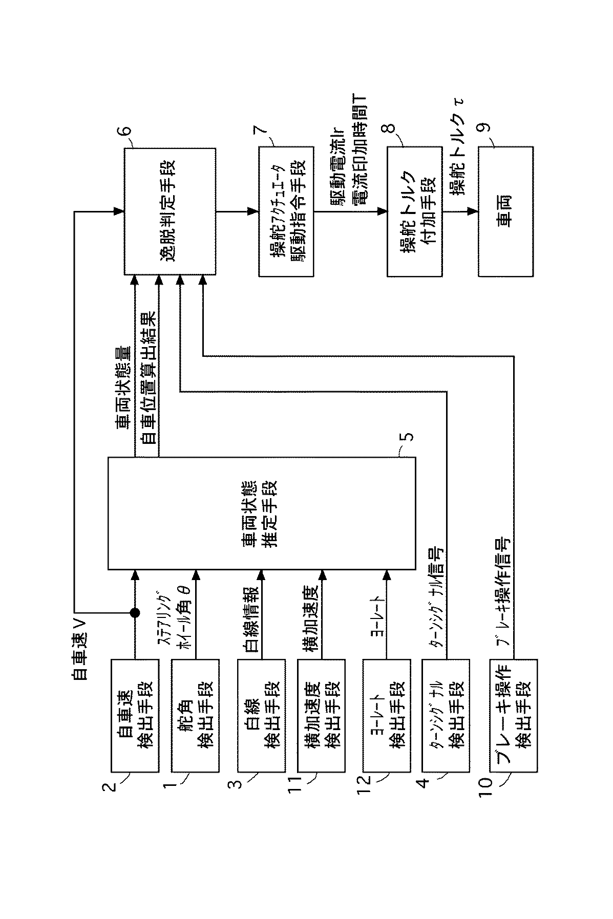
図2は第1実施例の車線逸脱警告装置の逸脱警告制御系ブロック図であり、図中、1は舵角検出手段(図1のステアリングホイール角センサ104に相当)、2は自車速検出手段(図1の車速センサ103に相当)、3は白線検出手段(図1の撮像装置101及び画像処理装置117に相当)、4はターンシグナル検出手段(図1のターンシグナルスイッチ105に相当)、5は車両状態推定手段(図1のコントロールユニット102に相当)、6は逸脱判定手段(図1のコントロールユニット102に相当)、7は操舵アクチュエータ駆動指令手段(図1のコントロールユニット102に相当)、8は操舵トルク付加手段(図1の操舵アクチュエータ100に相当)、9は車両、10はブレーキ操作検出手段(図1のブレーキペダルスイッチ106に相当)、11は横加速度検出手段(図1の横加速度センサ108に相当)、12はヨーレート検出手段(図1のヨーレートセンサ109に相当)である。
【0032】
前記車両状態推定手段5には、舵角検出手段1により得られるステアリングホイール角θと、自車速検出手段2により得られる自車速Vと、白線検出手段3により得られる道路形状情報や白線情報が入力され、これらの情報に基づいて、車両状態推定手段5は、自車両の状態量(基準となる走行中の車線中央からの横変位ycr、横速度dycr、ヨー角φ、ヨーレートγ=dφ)を算出する。なお、車両状態推定手段5に入力する信号としては、車両の状態量の精度を向上させるため、横加速度検出手段11により得られる横加速度や、ヨーレート検出手段により得られるヨーレートや、図外のナビゲーション情報などが加えられる。
【0033】
前記逸脱判定手段6は、車両状態推定手段5により推定された車両状態量および自車位置算出結果のうち、自車位置(白線からの距離ycdまたは車線中央からの距離ycr)、自車の向き(ヨー角φr)、自車速検出手段2からの自車速Vに基づいて、車両が左右どちらの車線方向に逸脱傾向があるかを判定する。ここで、車線の逸脱傾向を判定する際には、ターンシグナル検出手段4により得られるターンシグナル信号の有無や、ブレーキ操作検出手段10により得られるブレーキ操作の有無等により、運転者に車線変更の意思を確認し、運転者の車線変更の意思があると判断した場合には、逸脱警告(逸脱警報)の停止やアクチュエータ駆動電流の停止等の処理を行う。
【0034】
前記操舵アクチュエータ駆動指令手段7は、逸脱判定手段6による車線逸脱傾向判定結果と、車両状態推定手段5により推定された車両状態量および自車位置算出結果のうち、自車位置(白線からの距離ycdまたは車線中央からの距離ycr)、自車の向き(ヨー角φr)、自車速検出手段2からの自車速Vと、に基づいて、操舵トルク付加手段8に印加する駆動電流Irと電流印加時間Tを決定する。
【0035】
前記操舵トルク付加手段8は、操舵アクチュエータ駆動指令手段7で算出された駆動電流Irを、同じく操舵アクチュエータ駆動指令手段7で算出された電流印加時間Tをモータに印加することで、所望の操舵トルクτを車両の構成要素であるステアリングコラムに伝達し、車両の横方向の運動を発生させる。
【0036】
次に、作用を説明する。
【0037】
[操舵制御処理]
図3はコントロールユニット102で実行される操舵制御処理手順を表すフローチャートである。この操舵制御処理は、所定時間(例えば、10msec)毎のタイマ割込処理として実行される。
【0038】
先ず、ステップ12では、ステアリングホイール角センサ104からステアリングホイール角θを読み込み、車速センサ103から自車速Vを読み込み、画像処理装置117から白線検出座標を読み込み、ステップ15に移行する。
【0039】
次に、ステップ15では、ステアリングホイール角θ,自車速V,白線検出座標を用いて、車両状態推定手段5において、自車両の状態量(基準となる走行中の車線中央からの横変位ycr、横速度dycr、ヨー角φ、ヨーレートγ=dφ)を算出し、次のステップ16では、これらの車両状態量に基づいて、車両から白線までの距離ycdを算出する。
【0040】
次のステップ17では、ステップ16で算出されたヨー角φrと、車両から白線までの距離ycdと、車速センサ103から得られた自車速Vと、ターンシグナルスイッチ105から得られたターンシグナル信号等に基づいて、逸脱判定手段6において、運転者の意図しない車線逸脱を判定し、次いでステップ18に移行する。
【0041】
ステップ18では、ステップ17により、運転者の意図しない車線逸脱と判定された場合、操舵アクチュエータ駆動指令手段7において、車線逸脱を回避するのに必要なアクチュエータ駆動電流Irと電流印加時間Tを決定し、次いでステップ19に移行する。
【0042】
最後にステップ19では、ステップ18により決定されたアクチュエータ駆動電流Irが、同じくステップ18により決定された電流印加時間Tだけ印加されるように、実際にアクチュエータ(モータ)に流れる電流のサーボ処理を行う。
【0043】
[自車両状態量の推定法]
前記ステップ15における自車両状態量の推定法について説明する。
状態方程式と出力方程式で記述される動的システム
【式1】
【式2】
車両の運動方程式は次式で記述され、
【式3】
β:車体横滑り角、dφ:ヨーレート、
Cf(Cr):前(後)輪コーナリングパワー(二輪分)、
If(Ir):重心〜前(後)輪間距離、
δ:前輪実舵角、N:操舵系ギヤ比
白線を認識する撮像装置101は、前方LS[m]の注視点での目標軌道(車線中央)からの横変位を検出することができる。車両が目標軌道の近傍を走行する場合の近似式が、前方注視点での横変位ysrは、目標軌道からの相対横変位ycr,相対ヨー角φrを用いて次式により記述される。
【式4】
![]()
【式5】
![]()
【式6】
【0044】
[逸脱判断処理]
図4は図3のステップ17で実行される逸脱判断処理の手順を示すフローチャートであり、以下、各ステップについて説明する。
【0045】
先ず、ステップ32では、ターンシグナルスイッチ105により検出されたターンシグナル信号を用いて運転者の介入操作を判断する。ターンシグナルが検出された場合、ステップ36へ進み、ステップ36では、運転者の介入操作が行われたと判断して逸脱判定フラグF_dptに0を代入し、逸脱判断処理を終了する。そして、ステップ32でターンシグナルが検出されなかった場合、運転者の介入操作が行われなかったと判断してステップ33へ移行する。ここで、ターンシグナルについてのみ説明したが、同様に、運転者のブレーキ操作をブレーキペダルスイッチ106により検出して運転者の介入操作が行われたと判定しても良い。
【0046】
ステップ33では、車速Vと、ヨー角φrと、予め設定された逸脱余裕時間パラメータに基づいて、逸脱判定閾値ydを算出し、ステップ34へ移行する。
【0047】
ステップ34では、車両が右車線方向に逸脱傾向にあるかどうかが判定される。ステップ33で算出した逸脱判定閾値ydと車両の右前輪横変位を比較し、右前輪と右車線の間隔が逸脱判定閾値ydよりも小さい場合に右車線方向への逸脱傾向にあると判断して、ステップ37へ進み、ステップ37では、逸脱判定フラグF_dptに1を代入し、逸脱判断処理を終了する。右前輪と右車線の間隔が逸脱判定閾値ydよりも大きい場合には、左車線方向への逸脱傾向を判定するためにステップ35へ移行する。
【0048】
ステップ35では、車両が左車線方向に逸脱傾向にあるかどうかが判定される。ステップ33で算出した逸脱判定閾値ydと車両の左前輪横変位を比較し、左前輪と左車線の間隔が逸脱判定閾値ydよりも小さい場合に左車線方向への逸脱傾向にあると判断して、ステップ38へ進み、ステップ38では、逸脱判定フラグF_dptに−1を代入し、逸脱判断処理を終了する。また、左前輪と左車線の間隔が逸脱判定閾値ydよりも大きい場合に左右の車線中央部を自車が走行していて逸脱傾向にないと判断して、ステップ39へ進み、ステップ39では、逸脱判定フラグF_dptに0を代入し、逸脱判断処理を終了する。
【0049】
[アクチュエータ駆動電流設定処理]
図5は図3のステップ18で実行されるアクチュエータ駆動電流設定処理の手順を示すフローチャートであり、以下、各ステップについて説明する。
【0050】
先ず、ステップ52では、フラグF_actを参照し、本逸脱警告装置によるアクチュエータ駆動が既に行われているかどうかを判定する。参照したフラグF_actが0であり、アクチュエータ駆動が現時点で行われていなければ、ステップ53へ進み、ステップ53では、タイマー変数tをクリアし、ステップ56へ移行する。
【0051】
次に、ステップ56では、前記逸脱判断処理により得られた判定逸脱判定フラグF_dptを参照し、この値が0であれば、車両は左右の車線のどちらの方向にも逸脱していないと判断されるので、ステップ59へ進み、ステップ59では、アクチュエータ駆動電流Irに0を代入した後、ステップ63へ移行する。逸脱判定フラグF_dptが0以外の値である場合は、車両が左右どちらかへ逸脱傾向にあると判断されるので、ステップ57へ進み、ステップ57では、フラグF_actに1を代入してステップ60へ移行し、ステップ60では、車線逸脱を回避するのに必要なアクチュエータ駆動電流Irを算出し、ステップ62へ移行し、ステップ62では、ステップ60で算出されたアクチュエータ駆動電流Irと車両状態推定手段5で推定された車両状態量と、車速センサ103から読み込まれた自車速V等に基づいて、電流印加時間Tを設定し、ステップ63へ移行する。
【0052】
ステップ52で参照したフラグF_actが0以外の値を持っている場合、アクチュエータ駆動が既に行われているので、ステップ54において、電流印加時間を計測するタイマーtをdtだけインクリメントし、ステップ55へ移行する。ステップ55では、前記電流印加時間計測タイマーtが電流印加時間T未満かどうかが判定され、電流印加時間計測タイマーtが電流印加時間Tに満たない場合、アクチュエータ駆動電流Irと電流印加時間Tを保持したまま、ステップ63へ移行する。ステップ55において、電流印加時間計測タイマーtが電流印加時間Tに達した場合には、アクチュエータの駆動を停止する処理平行するため、ステップ58へ進み、ステップ58ではフラグF_actに0を代入し、次のステップ61へ進み、ステップ61では、アクチュエータ駆動電流Irに0を代入する。
【0053】
ステップ63では、アクチュエータ駆動電流に、フィルタ処理や時間遷移処理などを施すことにより駆動電流波形を整形し、最終的なアクチュエータ駆動電流波形を生成し、アクチュエータ駆動波形整形処理が終了したら、アクチュエータ駆動電流設定処理を終了する。
【0054】
[逸脱判断処理の具体的な演算内容例]
図6を用いて逸脱判断処理の具体的な演算内容例を説明する。
第1実施例では、基準となる車線に対する車両のヨー角φの大小に応じて逸脱判断の閾値を可変とするような処理を行っている。車両のヨー角絶対値|φ|が所定値φ0より小さい状態で、車両が逸脱傾向にある場合は、横ジャークを発生させる操舵制御の開始タイミングを、前輪が車線を跨ぐ程度に設定しても十分に逸脱を回避できる。また、運転者が車線逸脱傾向に認知することが多少遅れたとしても、車両の車線逸脱速度は十分に低いため、安全に逸脱回避操作を行うことが容易である。従って、操舵制御の開始タイミングを、前輪が車線を跨ぐ程度に設定しても十分に余裕を持って逸脱回避操作を行うことのできるヨー角φ0よりも車両の実ヨー角が大きい場合には、図6に示すように、ヨー角φの増加に応じて車両前輪と車線の距離ycdの大小を判断するための逸脱判定閾値ydを増加させる。また、同じヨー角φであっても車速Vの増加に応じて車線逸脱速度が増加してしまうことから、車速センサ103で検出された自車速Vの増加に応じて車両前輪と車線との距離ycdの大小を判断するための逸脱判定閾値ydを増加させる。第1実施例においては、逸脱余裕時間Tを定めた上で、下記の式(8)を用いて逸脱判定閾値ydを算出する。
yd=V×T×(|φ|−φ0) (8)
式(8)によると、逸脱判定閾値ydは、ヨー角φと自車速Vに比例しており、減時点から逸脱余裕時間Tを経過するまでの移動する車両の横移動量である。車両の前輪と車線との距離が逸脱判定閾値ydと比較して小さくなった場合、車両が逸脱傾向にあると判断し、判断のための条件式は下記の(9)式で与えられる。
【0055】
逸脱判断条件
w/2−yd<ycd (右車線方向へ逸脱)
ycd<−w/2+yd (左車線方向へ逸脱) (9)
ただし、wは車線の巾である。また、ycdは走行中の車線を基準とした前輪の横変位であり、
ycd=ycr+H/2(右前輪)
ycd=ycr+H/2(左前輪) (10)
の式を用いて算出する。
【0056】
[アクチュエータ駆動電流設定処理の具体的な演算内容例]
図7を用いてアクチュエータ駆動電流設定処理の具体的な演算内容例を説明する。
第1実施例では、逸脱判断処理において逸脱傾向にあると判断された場合、逸脱傾向にあると判定された時点での車両のヨー角φrを記憶する。
逸脱傾向にあると判定された時点での車両のヨー角φrが大きい場合には、運転者がより早く逸脱回避操作を行うことが要求されるため、車両の横ジャークを大きめに発生させて強めの警告を発することができるように、アクチュエータ駆動電流Irも大きい値を代入する。図7に示されている第1実施例においては、前記逸脱判断処理で用いたヨー角の所定値φ0の前後において、アクチュエータ駆動電流Irの大小を切り替える構成としているが、アクチュエータ駆動電流Irの切り替えには、前記逸脱判断処理で用いたφ0とは独立な値を用いても良いし、アクチュエータ駆動電流Irの切り替えの数を、第1実施例で用いた2段階ではなく、3段階にしたり、4段階以上にしたり、さらには、無段階にしても良い。
【0057】
アクチュエータ駆動電流Irに大きな値が代入されるのは、車線逸脱時の車両のヨー角φrが大きかった場合であるが、このような場合には、前記逸脱判断処理においても逸脱判定タイミングを早める処理を行っているため、単純にアクチュエータ駆動電流Irを大きい値にしてしまうと、車両が車線内側に戻りすぎてしまう。これを避けるため、第1実施例では、印加する電流の大きさに応じて、図7に示すように、電流印加時間を可変とし、アクチュエータ駆動電流Irをアクチュエータに印加した場合に車両に発生するヨーレートを用いてヨー角が0または所定値φr(ゼロに近い値)になるまでの時間Tを算出し、これを電流印加時間としている。電流印加時間Tは、下記の(11)式により算出される。
T=(φr−φ)/(K*Ir) (11)
ただし、Kは予め測定されたヨーレートゲインであり、外乱によるロバスト性を向上させたければヨーレートセンサ109により検出されたヨーレートγを用いて、
T=(φr−φ)/γ (12)
により電流印加時間を設定して良い。
これにより、車両のヨー角が大きいような場合であって、運転者に急いで適切な操作を促す必要があると考えられるような場合には、大きめの横ジャークを車両に発生させて運転者の強く警告することができ、かつ、逸脱警告後に車両が車線内側に向きすぎて反対側の車線方向に走行してしまうことも防止することができる。
【0058】
[逸脱警告作用]
図8(a)はアクチュエータ駆動電流波形を示す図、図8(b)は図8(a)に示すアクチュエータ駆動電流波形を印加した場合の車両横加速度特性を示す図、図8(c)は図8(a)に示すアクチュエータ駆動電流波形を印加した場合の車両横ジャーク特性図である。
【0059】
図8の破線は従来例であり、車両状態量の時間的に連続なフィードバック制御によりアクチュエータ駆動電流を算出したような場合を表している。従来例の場合、車両状態量の時間的に連続なフィードバック制御を行っているため、車線に接近するにつれて、徐々にアクチュエータ駆動電流Irが増加し、操舵アクチュエータの発生する操舵トルクが滑らかに発生することにより、車両の横加速度、横ジャークが共に小さい値に保たれ、その結果、運転者は車両が車線から逸脱傾向にあることをあまり意識しないまま、車両の車線逸脱が回避される。
【0060】
これに対して、第1実施例の場合、実線で示すように、車両前輪と車線との距離が逸脱判定閾値ydよりも接近したところで、車両の状態量によらない方形波入力で操舵アクチュエータ100が駆動される。方形波入力の立ち上がり時は、瞬時に0[A]からIr[A]の電流が操舵アクチュエータ100に印加されるため、印加電流に比例して操舵トルクも急激に増加する。操舵トルクは、ステアリングホイール角θや車両の横加速度と相関が強く、したがって、ステアリングホイール角θの微分値であるステアリングホイール角速度や横加速度の微分値である横ジャークは、操舵トルクの微分値、すなわち、操舵アクチュエータ100に印加される電流値の単位時間当たりの変化巾と強い相関がある。
【0061】
したがって、車両が車線に逸脱傾向にあると判断された場合、車線に接近中の車両の状態量によらない所定値以上の絶対値を持つ方形波入力で操舵アクチュエータ100を駆動することにより、所定値以上の横ジャークを車両に発生させることができる。人間はジャークに敏感であるため、自車両が車線逸脱傾向にあることや、適切な操舵方向を瞬時に認知することができるので、運転者の適切かつ迅速な車線逸脱回避操作を促すことができる。
【0062】
例えば、横加速度を必要としない直線路を走行中であっても、初心者の運転のように、頻繁に修正操舵を行った場合は横加速度が変動し、乗り心地が悪化する。すなわち、横加速度の変動に対して人間は非常に敏感である。横加速度の変動を表す量として、横ジャーク(横加速度の微分値≒単位時間当たりの横加速度の変化量)が定義され、車線逸脱時には、積極的に横ジャークを車線内側に向けて発生させることにより、運転者の適切で迅速な回避操舵を促すことができる。
逆に、横ジャークの発生が小さい状態で走行することができれば、カーブを走行中のようにある程度大きな横加速度が生じた場合でも、乗員に与える不快感は小さい。
【0063】
次に、効果を説明する。
【0064】
(1)車両が走行路から逸脱傾向にあるかどうかを判定する逸脱判定手段6と、車両が走行路から逸脱傾向にあると判定された場合、車両に所定値以上の横ジャークを車線内側に向けて発生させる車線逸脱警告手段として操舵アクチュエータ駆動指令手段7とを設けたため、運転者が意図しない車線逸脱傾向時、運転者は横ジャークを敏感に感じとることにより、適切な操舵方向が瞬時に認識され、運転者の適切かつ迅速な車線逸脱回避操作を促すことができる。
【0065】
(2)車線逸脱警告手段として操舵アクチュエータ駆動指令手段7が用いられ、操舵アクチュエータ駆動指令手段7において、逸脱判定手段6により車両が走行路から逸脱傾向にあると判定された場合、車両に所定値以上の横ジャークが車線内側に向けて発生するように、操舵アクチュエータ100を駆動するようにしたため、操舵アクチュエータを備えたレーンキープ制御システム等が搭載された車両の場合、新たに操舵アクチュエータ100を設ける必要なく、既存の操舵アクチュエータ100を車線逸脱警告手段として流用することができる。
【0066】
(3)操舵アクチュエータ駆動指令手段7において、操舵アクチュエータ100への駆動電流制御を、車両状態量によらないで、逸脱判定直前の逸脱条件から決まるステップ入力による開ループ制御により行なう、すなわち、車線逸脱警告時の操舵アクチュエータ100の駆動に関しては、車両状態量を用いた時間的に連続なフィードバック制御ではなく、逸脱判定直前の逸脱条件(例えば、逸脱方向と逸脱速度)から決まるステップ入力による開ループ制御としているため、車両状態推定量のノイズ成分による不要な制御を遮断でき、一方向のみに操舵トルクと横加速度が発生し、正しい進行方向を確実に運転者に伝えることができる。
さらに、逸脱警告開始後に白線検出に不具合が生じた場合であっても、アクチュエータ制御を続行することができるので、撮像装置101の白線を検出する信頼性を必要以上に高めなくても逸脱警告装置としての信頼性を保つことができる。
【0067】
(4)操舵アクチュエータ駆動指令手段7において、操舵アクチュエータ100への駆動電流の入力波形が、車両ヨー角φが大きいほどアクチュエータ駆動電流Irが大きくなるように切り替えられるため、ヨー角φが大きく運転者への警告に緊急を要する場合には、強めの横ジャークを発生させることができ、運転者の迅速な逸脱回避操作を促す効果がある。
【0068】
(5)操舵アクチュエータ駆動指令手段7において、逸脱判定直前の車両ヨー角φに基づき、逸脱回避操作終了後の車両のヨー角がゼロもしくはゼロに近い所定値φrとなるように、操舵アクチュエータ100への電流印加時間Tが設定されるため、逸脱警告開始時のアクチュエータ駆動電流Irの大小にかかわらず、逸脱警告終了後の車両の走行状態を一様に保つことができる。
【0069】
(第2実施例)
第2実施例は、図9の実線に示すように、操舵アクチュエータ100に印加する駆動電流波形を、立ち上がり時と立ち下がり時に傾きを与えた台形波入力とした例である。ここで、図9(a)はアクチュエータ駆動電流波形を示す図、図9(b)は図9(a)に示すアクチュエータ駆動電流波形を印加した場合の車両横加速度特性を示す図、図9(c)は図9(a)に示すアクチュエータ駆動電流波形を印加した場合の車両横ジャーク特性図であり、実線は第1実施例である。
なお、第2実施例の他の構成及び作用は第1実施例と同様であるので、図示並びに説明を省略する。
【0070】
次に、効果を説明する。
【0071】
この第2実施例の車線逸脱警告装置では、第1実施例の効果に加え、下記の効果を得ることができる。
【0072】
(6)操舵アクチュエータ駆動指令手段7において、操舵アクチュエータ100への駆動電流制御が、車両状態量によらないで、逸脱判定直前の逸脱条件から決まる台形波入力による開ループ制御により行うため、台形波入力の立ち上がり波形、および、立ち下がり波形の傾きが変えることで、図9(c)の横ジャーク調整代に示すように、車両の横ジャークの大きさを任意の値に設定する横ジャーク調整機能を得ることができる。
すなわち、車両の横ジャークは、横加速度の単位時間当たりの変化量であることから、操舵トルクの変化速度を変えることにより、横ジャークの大きさを変えることができる。そして、操舵トルクの変化速度は、アクチュエータ駆動電流の変化速度と等価である。
【0073】
(第3実施例)
第3実施例は、第2実施例と同様に、操舵アクチュエータ100に印加する駆動電流波形を、立ち上がり時と立ち下がり時に傾きを与えた台形波入力とすると共に、図9の破線に示す立ち下がり波形の傾きを、図9の実線に示す立ち上がり波形の傾きに比べて小さい値に設定した例である。なお、第3実施例の他の構成及び作用は第1実施例と同様であるので、図示並びに説明を省略する。
【0074】
次に、効果を説明する。
【0075】
この第3実施例の車線逸脱警告装置では、第1実施例及び第2実施例の効果に加え、下記の効果を得ることができる。
【0076】
(7)操舵アクチュエータ駆動指令手段7において、操舵アクチュエータ100への駆動電流を、立ち上がり時と立ち下がり時に傾きを与えた台形波入力とし、立ち下がり波形の傾きを立ち上がり波形の傾きに比べて小さい値に設定したため、図9(c)の横ジャーク調整代に示すように、逸脱警告終了時に横ジャークの反動成分が抑制され、逸脱警告後の運転者のステアリング操作に対する干渉を減らすことができる。
すなわち、車両の横ジャークの大きさは、横加速度の微分値(単位時間当たりの横加速度の変化量)であることから、アクチュエータ駆動電流の波形を、立ち上がり側と立ち下がり側とで同じ波形に設定すると、図9(c)の実線特性に示すように、逸脱警告終了時には逸脱警告に使用した横ジャークと同じ大きさの反動成分が発生することになる。
なお、立ち上がり波形は、台形入力ではなく、第1実施例のように、ステップ入力であっても適用することができる。
【0077】
(第4実施例)
第4実施例は、第1実施例と同様に、操舵アクチュエータ100に印加する駆動電流波形の立ち下がり波形をステップ入力とし、立ち下がり波形を、図10(a)の実線に示すように、入力をステップ入力とする1次遅れ特性のローパスフィルタの出力で与えるようにした例である。ここで、図10(a)はアクチュエータ駆動電流波形を示す図、図10(b)は図10(a)に示すアクチュエータ駆動電流波形を印加した場合の車両横加速度特性を示す図、図10(c)は図10(a)に示すアクチュエータ駆動電流波形を印加した場合の車両横ジャーク特性図であり、実線は第4実施例である。
なお、第4実施例の他の構成及び作用は第1実施例と同様であるので、図示並びに説明を省略する。
【0078】
次に、効果を説明する。
【0079】
この第4実施例の車線逸脱警告装置では、第1実施例の効果に加え、下記の効果を得ることができる。
【0080】
(8)操舵アクチュエータ駆動指令手段7において、操舵アクチュエータ100への駆動電流の立ち下がり波形が、入力をステップ入力とするローパスフィルタの出力で与えられるため、入力をステップ入力とする簡単なローパスフィルタ処理により、図10(c)の第4実施例による効果代に示すように、逸脱警告終了時に横ジャークの反動成分を抑制する駆動電流の立ち下がり波形を得ることができる。
【0081】
(第5実施例)
第5実施例は、第1実施例と同様に、操舵アクチュエータ100に印加する駆動電流波形の立ち下がり波形をステップ入力とし、立ち下がり波形を、図10(a)の実線に示すように、入力をステップ入力とする2次遅れ特性のローパスフィルタの出力で与えるようにした例である。なお、第5実施例の他の構成及び作用は第1実施例と同様であるので、図示並びに説明を省略する。
【0082】
次に、効果を説明する。
【0083】
この第5実施例の車線逸脱警告装置では、第1実施例の効果に加え、下記の効果を得ることができる。
【0084】
(9)操舵アクチュエータ駆動指令手段7において、操舵アクチュエータ100への駆動電流の立ち下がり波形が、2次の遅れ特性を有するローパスフィルタにより生成されるため、図10(c)の第5実施例による効果代に示すように、アクチュエータ駆動電流Irの停止遷移処理を行ったときに生じる停止遷移処理開始直後の不連続性が回避され、横ジャークの反動成分が滑らかに抑制され、逸脱警告後の運転者のステアリング操作に対する干渉をより減らすことができる。
すなわち、2次以上の遅れ特性を有するローパスフィルタの場合、ステップ応答波形として、ステップ入力直後の傾きは小さく、時間の経過と共に徐々に傾きを大きくしてゆくという設定が容易に実現できる。
【0085】
(他の実施例)
以上、本発明の車線逸脱警告装置を第1実施例ないし第5実施例に基づき説明してきたが、具体的な構成については、これらの実施例に限られるものではなく、特許請求の範囲の各請求項に係る発明の要旨を逸脱しない限り、設計の変更や追加等は許容される。
【0086】
例えば、第1〜第5実施例では、車線逸脱警告として横ジャークを車両に発生させる手段として、操舵アクチュエータを用いて操舵トルクを与える手段の例を示したが、非制動操作時においても各輪のブレーキ液圧を独立に制御できるブレーキ液圧アクチュエータを用い、逸脱判定時に左右輪に制動力差を与えることで横ジャークを車両に発生させるようにしても良い。
【0087】
また、第1〜第5実施例では、逸脱判定手段として、車速Vと逸脱余裕時間Tとヨー角φにより逸脱判定閾値ydを決め、車線巾wと前輪横変位ycdとにより逸脱判断条件を決める例を示したが、具体的な逸脱判定手法は、実施例に示した手法以外の手法を用いても良い。
【図面の簡単な説明】
【図1】第1実施例の車線逸脱警告装置を示す概略構成図である。
【図2】第1実施例の車線逸脱警告装置の逸脱警告制御系ブロック図である。
【図3】第1実施例装置のコントロールユニットで実行される操舵制御処理手順を示すフローチャートである。
【図4】第1実施例装置のコントロールユニットで実行される逸脱判断処理手順を示すフローチャートである。
【図5】第1実施例装置のコントロールユニットで実行されるアクチュエータ駆動電流設定処理手順を示すフローチャートである。
【図6】第1実施例装置での逸脱判断処理例を示す図である。
【図7】第1実施例装置でのアクチュエータ駆動電流設定処理例を示す図である。
【図8】第1実施例における駆動電流波形と車両横加速度と横ジャークと、従来例における駆動電流波形と車両横加速度と横ジャークとの比較特性図である。
【図9】第2実施例における駆動電流波形と車両横加速度と横ジャークと、第3実施例における駆動電流波形と車両横加速度と横ジャークと、従来例における駆動電流波形と車両横加速度と横ジャークとの比較特性図である。
【図10】第4実施例における駆動電流波形と車両横加速度と横ジャークと、第5実施例における駆動電流波形と車両横加速度と横ジャークと、従来例における駆動電流波形と車両横加速度と横ジャークとの比較特性図である。
【符号の説明】
1 舵角検出手段
2 自車速検出手段
3 白線検出手段
4 ターンシグナル検出手段
5 車両状態推定手段
6 逸脱判定手段
7 操舵アクチュエータ駆動指令手段
8 操舵トルク付加手段
9 車両
10 ブレーキ操作検出手段
11 横加速度検出手段
12 ヨーレート検出手段
100 操舵アクチュエータ
101 撮像装置
102 コントロールユニット
103 車速センサ
104 ステアリングホイール角センサ
105 ターンシグナルスイッチ
106 ブレーキペダルスイッチ
107 油圧パワーステアリング装置
108 横加速度センサ
109 ヨーレートセンサ
110 右前輪
111 左前輪
112 ステアリングラック
113 ステアリングホイール
114 ナビゲーション装置
115 ステアリングシャフト
116 ブザー・スピーカー
117 画像処理装置[0001]
BACKGROUND OF THE INVENTION
The present invention belongs to the technical field of a lane departure warning device that gives a warning that prompts a driver to perform a departure avoidance operation when it is determined that a vehicle tends to depart from a road.
[0002]
[Prior art]
Conventionally, as a lane departure warning device, for example, a device described in JP-A-11-180327 is known. In this publication, the lateral deviation amount calculating means calculates the lateral deviation amount of the vehicle travel position from the reference position of the travel lane, and is used for steering that can be easily overcome by the driver based on the calculated lateral deviation amount. A technique for calculating a control torque and driving a steering actuator is described.
[0003]
In addition, as a technique for preventing the generation of steering control torque at a travel position that suits the driver's preference, the yaw angle formed by the traveling direction of the vehicle with respect to the travel lane, not the amount of lateral deviation with respect to the travel lane, is provided. Based on the above, the following technique for driving a steering actuator has been proposed.
[0004]
For example, in Japanese Patent Laid-Open No. 11-189166, a yaw angle formed by a traveling direction of a vehicle with respect to a traveling lane is calculated, and a steering wheel having a size that can be easily overcome by a driver based on the calculated yaw angle. By calculating the control torque and driving the steering actuator, the driver's steering operation is urged so that the traveling direction of the vehicle is along the traveling lane, and guidance for prevention of lane departure is provided.
[0005]
[Problems to be solved by the invention]
However, in all of the conventional lane departure warning devices, the steering control torque is gradually increased when the lateral deviation amount of the vehicle increases or the degree of approach to the white line increases. Since the movement is smooth, it may be delayed for the driver to notice the departure of the vehicle from the lane. That is, even if a deviation is temporarily avoided by the steering control torque, an unstable state in which the vehicle is still likely to deviate from the lane is not preferable, and it is necessary to make the driver notice early.
[0006]
The present invention has been made paying attention to the above-mentioned problems, and an object of the present invention is to provide a lane departure warning device that can prompt the driver to perform appropriate and quick avoidance steering at the time of lane departure. is there.
[0007]
[Means for Solving the Problems]
In order to achieve the above object, in the invention according to
Departure determination means for determining whether or not the vehicle has a departure tendency from the road;
When it is determined by the departure determination means that the vehicle has a tendency to depart from the road,Warning lane departureLane departure warning means,
WithLane departure warning device
The departure determination means determines a lane inner side direction toward the center of the lane according to whether the vehicle has a departure tendency in the right lane direction or a departure tendency in the left lane direction from the road,
Provide a steering actuator that applies driving force to the steering mechanism of the vehicle,
When the lane departure warning means determines that the vehicle has a tendency to depart from the road by the departure determination means, a lateral jerk as an amount representing a change in lateral acceleration is generated in the vehicle toward the inside of the lane. Actuator driving means for driving the steering actuator by an instantly rising currentIt is characterized by that.
[0009]
Claim 2In the invention according toClaim 1In the lane departure warning device described in
The actuator driving means controls the drive current to the steering actuator.Rather than continuous feedback control using vehicle state quantities,By step input determined from the departure condition immediately before departure judgmentOpen loopIt is a means to perform by control.
[0010]
Claim 3In the invention according toClaim 1In the lane departure warning device described in
The actuator driving means controls the drive current to the steering actuator.Rather than continuous feedback control using vehicle state quantities,By trapezoidal wave input determined from the departure condition immediately before departure judgmentOpen loopIt is a means provided with a lateral jerk adjusting means by changing the rising waveform of the trapezoidal wave input and the slope of the falling waveform as well as performing the control.
[0011]
Claim 4In the invention according toClaim 1In the lane departure warning device described in
The actuator driving means is configured to input a driving current to the steering actuator, at least a rising waveform is step input, orTrapezoidal wave inputIn this case, the slope of the falling waveform is set to a value smaller than the slope of the rising waveform.
[0012]
Claim 5In the invention according toClaim 4In the lane departure warning device described in
The actuator driving means is a means for giving a falling waveform of a driving current to the steering actuator as an output of a low-pass filter having an input as a step input.
[0013]
Claim 6In the invention according toClaim 5In the lane departure warning device described in
The actuator driving means is characterized in that the low-pass filter for generating the falling waveform of the driving current to the steering actuator has a second-order or higher delay characteristic.
[0014]
Claim 7In the invention according toAny one of
Providing a yaw angle detection means for detecting the vehicle yaw angle;
The actuator driving means is a means for switching the input waveform of the driving current to the steering actuator so that the current value increases as the vehicle yaw angle increases.
[0015]
Claim 8In the invention according toClaim 7In the lane departure warning device described in
The actuator driving means sets a current application time to the steering actuator based on the vehicle yaw angle immediately before the departure determination so that the yaw angle of the vehicle after the departure avoidance operation becomes zero or a predetermined value close to zero. It is a means provided with the electric current application time setting means, It is characterized by the above-mentioned.
[0016]
Operation and effect of the invention
In the invention according to
thisTherefore, when the driver tends to deviate from a lane that is not intended, the driver feels the lateral jerk sensitively so that the appropriate steering direction can be instantly recognized, and the driver can prompt the driver to perform an appropriate and quick lane departure avoidance operation. .
For example, even if the vehicle is traveling on a straight road that does not require lateral acceleration, if the corrective steering is frequently performed as in the case of a beginner's driving, the lateral acceleration fluctuates and the riding comfort deteriorates. That is, humans are very sensitive to changes in lateral acceleration. Lateral jerk (differential value of lateral acceleration ≒ amount of change in lateral acceleration per unit time) is defined as an amount representing the fluctuation of lateral acceleration, and when the vehicle departs from the lane, the lateral jerk should be actively generated toward the inside of the lane. Thus, it is possible to prompt the driver to perform appropriate and quick avoidance steering.
On the other hand, if the vehicle can travel with little occurrence of lateral jerk, even if a certain amount of lateral acceleration occurs during traveling on a curve, the discomfort given to the occupant is small.
In addition, since the actuator driving means is used as the lane departure warning means, in a vehicle equipped with a lane keeping control system equipped with a steering actuator, it is not necessary to provide a new steering actuator, and the existing steering actuator is replaced with the lane departure warning. It can be used as a means.
[0018]
Claim 2In the invention according to the above, in the actuator driving means, the drive current control to the steering actuator isRather than continuous feedback control using vehicle state quantities,This is performed by open loop control by step input determined from the departure condition immediately before departure determination.
In other words, regarding the driving of the steering actuator at the time of lane departure warning, it is not based on temporally continuous feedback control using the vehicle state quantity, but by step input determined from the departure condition (for example, departure direction and departure speed) immediately before departure determination. By using the open loop control, unnecessary control due to the noise component of the vehicle state estimation amount can be cut off, steering torque and lateral acceleration are generated only in one direction, and the correct traveling direction can be reliably transmitted to the driver.
Furthermore, even if a defect occurs in the detection of the white line after the departure warning starts, the actuator control can be continued. Therefore, even if the reliability of detecting the white line of the imaging device is not increased more than necessary, the departure warning device can be used. Can be kept reliable.
[0019]
Claim 3In the invention according to the above, in the actuator driving means, the drive current control to the steering actuator isRather than continuous feedback control using vehicle state quantities,It is performed by open loop control with trapezoidal wave input determined from the deviation condition immediately before departure judgment, and the slope of the rising and falling waveforms of the trapezoidal wave input is changed in the lateral jerk adjustment means, so the lateral jerk of the vehicle The size can be set to an arbitrary value. That is, since the lateral jerk of the vehicle is a change amount of the lateral acceleration per unit time, the size of the lateral jerk can be changed by changing the change speed of the steering torque. The change speed of the steering torque is equivalent to the change speed of the actuator drive current.
[0020]
Claim 4In the invention according to the above, in the actuator driving means, the drive current to the steering actuator is at least a rising waveform step input, orTrapezoidal wave inputSince the slope of the falling waveform is set to a smaller value than the slope of the rising waveform, the reaction component of the lateral jerk is suppressed at the end of the departure warning, reducing the interference with the driver's steering operation after the departure warning. be able to.
In other words, since the size of the lateral jerk of the vehicle is the differential value of lateral acceleration (the amount of change in lateral acceleration per unit time), the actuator drive current waveform is the same on the rising and falling sides. If set, a reaction component having the same magnitude as the lateral jerk used for the departure warning is generated at the end of the departure warning.
[0021]
Claim 5In the invention according to the present invention, in the actuator driving means, the falling waveform of the driving current to the steering actuator is given by the output of the low-pass filter whose input is the step input, so the simple low-pass filter whose input is the step input By the processing, it is possible to obtain a falling waveform of the drive current that suppresses the reaction component of the lateral jerk at the end of the departure warning.
[0022]
Claim 6In the invention according to the present invention, in the actuator driving means, the falling waveform of the driving current to the steering actuator is generated by the low-pass filter having a second-order or higher delay characteristic. The discontinuity immediately after the start of the stop transition process that occurs at the time is avoided, the reaction component of the lateral jerk is smoothly suppressed, and interference with the driver's steering operation after the departure warning can be further reduced.
That is, in the case of a low-pass filter having a delay characteristic of second order or higher, the step response waveform can be easily set so that the gradient immediately after step input is small and the gradient is gradually increased with time. In addition, when a low-pass filter having a first-order delay characteristic or a trapezoidal waveform is used, discontinuity occurs immediately after the stop transition process is started when the actuator drive current stop transition process is performed.
[0023]
Claim 7In the invention according to the present invention, in the actuator driving means, the input waveform of the driving current to the steering actuator is switched so that the current value increases as the vehicle yaw angle increases. When an emergency is required, a strong lateral jerk can be generated, which has an effect of prompting the driver to perform a quick departure avoidance operation.
[0024]
Claim 8In the invention according to the present invention, in the current application time setting means of the actuator driving means, based on the vehicle yaw angle immediately before departure determination, the yaw angle of the vehicle after completion of the departure avoidance operation becomes zero or a predetermined value close to zero. In addition, since the current application time to the steering actuator is set, the running state of the vehicle after the departure warning can be kept uniform regardless of the magnitude of the actuator drive current at the start of the departure warning.
[0025]
DETAILED DESCRIPTION OF THE INVENTION
Hereinafter, an embodiment for realizing a lane departure warning device according to the present invention is claimed.1, 2, 7, 8A first embodiment corresponding to claim 1 and claims3, 4And a second embodiment corresponding to5, 6And a third embodiment corresponding to the above.
[0026]
(First embodiment)
First, the configuration will be described.
FIG. 1 is a schematic configuration diagram showing a lane departure warning device of the first embodiment, in which 100 is a steering actuator, 101 is an imaging device, 102 is a control unit, 103 is a vehicle speed sensor, 104 is a steering wheel angle sensor, 105 is a turn signal switch, 106 is a brake pedal switch, 107 is a hydraulic power steering device, 108 is a lateral acceleration sensor, 109 is a yaw rate sensor, 110 is a right front wheel, 111 is a left front wheel, 112 is a steering rack, 113 is a steering wheel, 114 is a navigation device, 115 is a steering shaft, 116 is a buzzer speaker, and 117 is an image processing device.
[0027]
The
[0028]
The
[0029]
The
[0030]
The
[0031]
FIG. 2 is a block diagram of a departure warning control system of the lane departure warning device of the first embodiment, in which 1 is a steering angle detection means (corresponding to the steering
[0032]
The vehicle state estimation means 5 includes the steering wheel angle θ obtained by the steering angle detection means 1, the own vehicle speed V obtained by the own vehicle speed detection means 2, and road shape information and white line information obtained by the white line detection means 3. Based on this information, the vehicle state estimation means 5 determines the state quantity of the host vehicle (the lateral displacement ycr, the lateral speed dycr, the yaw angle φ, the yaw rate γ = dφ from the center of the running lane serving as a reference) Is calculated. As a signal to be input to the vehicle state estimation means 5, in order to improve the accuracy of the vehicle state quantity, the lateral acceleration obtained by the lateral acceleration detection means 11, the yaw rate obtained by the yaw rate detection means, navigation not shown in the figure. Information is added.
[0033]
The departure determination means 6 includes the vehicle position (the distance ycd from the white line or the distance ycr from the center of the lane) of the vehicle state quantity and the vehicle position calculation result estimated by the vehicle state estimation means 5 and the direction of the vehicle. Based on the (yaw angle φr) and the own vehicle speed V from the own vehicle
[0034]
The steering actuator drive command means 7 includes the vehicle position (distance from the white line) of the lane departure tendency determination result by the departure determination means 6, the vehicle state quantity estimated by the vehicle state estimation means 5 and the own vehicle position calculation result. drive current Ir applied to the steering torque adding means 8 and current application based on ycd or distance ycr from the center of the lane), direction of the own vehicle (yaw angle φr), and own vehicle speed V from the own vehicle
[0035]
The steering torque adding means 8 applies the drive current Ir calculated by the steering actuator drive command means 7 and the current application time T calculated by the steering actuator drive command means 7 to the motor, so that a desired steering torque is obtained. τ is transmitted to the steering column, which is a component of the vehicle, to generate lateral movement of the vehicle.
[0036]
Next, the operation will be described.
[0037]
[Steering control processing]
FIG. 3 is a flowchart showing a steering control processing procedure executed by the
[0038]
First, in
[0039]
Next, in
[0040]
In the
[0041]
In
[0042]
Finally, in
[0043]
[Method for estimating the amount of vehicle state]
The method for estimating the host vehicle state quantity in
Dynamic system described by state equation and output equation
[Formula 1]
[Formula 2]
The equation of motion of the vehicle is described by
[Formula 3]
β: body slip angle, dφ: yaw rate,
Cf(Cr): Front (rear) wheel cornering power (for two wheels),
If(Ir): Center of gravity to front (rear) distance between wheels,
δ: Front wheel actual steering angle, N: Steering system gear ratio
The
[Formula 4]
![]()
[Formula 5]
![]()
[Formula 6]
[0044]
[Deviation judgment processing]
FIG. 4 is a flowchart showing the procedure of the departure determination process executed in
[0045]
First, in
[0046]
In
[0047]
In
[0048]
In
[0049]
[Actuator drive current setting process]
FIG. 5 is a flowchart showing the procedure of the actuator drive current setting process executed in
[0050]
First, in
[0051]
Next, in
[0052]
If the flag F_act referred to in
[0053]
In
[0054]
[Specific calculation example of deviation judgment processing]
A specific calculation example of the deviation determination process will be described with reference to FIG.
In the first embodiment, processing is performed to vary the threshold value for deviation determination according to the magnitude of the yaw angle φ of the vehicle with respect to the reference lane. If the vehicle yaw angle absolute value | φ | is smaller than the predetermined value φ0 and the vehicle tends to deviate, the start timing of the steering control that generates the lateral jerk may be set so that the front wheels cross the lane. Deviations can be avoided sufficiently. Even if the driver is slightly delayed in recognizing the tendency to depart from the lane, the lane departure speed of the vehicle is sufficiently low, so that it is easy to safely perform the departure avoidance operation. Therefore, when the actual yaw angle of the vehicle is larger than the yaw angle φ0 that can perform the departure avoidance operation with a sufficient margin even if the start timing of the steering control is set so that the front wheels cross the lane, As shown in FIG. 6, the deviation determination threshold value yd for determining the magnitude of the distance ycd between the vehicle front wheel and the lane is increased in accordance with the increase in the yaw angle φ. Further, even if the yaw angle φ is the same, the lane departure speed increases as the vehicle speed V increases. Therefore, the distance between the vehicle front wheel and the lane according to the increase in the host vehicle speed V detected by the
yd = V × T × (| φ | −φ0) (8)
According to equation (8), the departure determination threshold value yd is proportional to the yaw angle φ and the host vehicle speed V, and is the lateral movement amount of the moving vehicle from the point of decrease until the departure margin time T elapses. When the distance between the front wheels of the vehicle and the lane becomes smaller than the departure determination threshold value yd, it is determined that the vehicle is in a departure tendency, and a conditional expression for determination is given by the following expression (9).
[0055]
Deviation judgment conditions
w / 2−yd <ycd (deviation in the right lane direction)
ycd <-w / 2 + yd (deviation in the left lane direction) (9)
Where w is the width of the lane. Ycd is the lateral displacement of the front wheel relative to the running lane,
ycd = ycr + H / 2 (right front wheel)
ycd = ycr + H / 2 (front left wheel) (10)
This is calculated using the following formula.
[0056]
[Specific calculation example of actuator drive current setting process]
A specific calculation example of the actuator drive current setting process will be described with reference to FIG.
In the first embodiment, when it is determined that there is a departure tendency in the departure determination process, the yaw angle φr of the vehicle when it is determined that there is a departure tendency is stored.
If the yaw angle φr of the vehicle at the time when it is determined that the vehicle tends to deviate is large, the driver is required to perform the departure avoidance operation earlier. A large value is also substituted for the actuator drive current Ir so that the above warning can be issued. In the first embodiment shown in FIG. 7, the actuator drive current Ir is switched between before and after the predetermined value φ0 of the yaw angle used in the departure determination process. For this, a value independent of φ0 used in the deviation determination process may be used, and the number of switching of the actuator drive current Ir is set to three stages instead of the two stages used in the first embodiment. There may be four or more steps, or even no steps.
[0057]
A large value is substituted for the actuator drive current Ir when the vehicle yaw angle φr when the vehicle departs from the lane is large. In such a case, the process for advancing the departure determination timing in the departure determination process as well. Therefore, if the actuator drive current Ir is simply set to a large value, the vehicle returns too much to the inside of the lane. In order to avoid this, in the first embodiment, as shown in FIG. 7, the current application time is made variable in accordance with the magnitude of the current to be applied, and this occurs in the vehicle when the actuator drive current Ir is applied to the actuator. Using the yaw rate, a time T until the yaw angle reaches 0 or a predetermined value φr (a value close to zero) is calculated, and this is used as the current application time. The current application time T is calculated by the following equation (11).
T = (φr−φ) / (K * Ir) (11)
However, K is a yaw rate gain measured in advance, and in order to improve robustness due to disturbance, the yaw rate γ detected by the
T = (φr−φ) / γ (12)
The current application time may be set by
As a result, if the yaw angle of the vehicle is large and it is considered necessary to prompt the driver to perform an appropriate operation, a large lateral jerk is generated in the vehicle. It is also possible to prevent the vehicle from traveling too far inward of the lane and traveling in the opposite lane direction after the departure warning.
[0058]
[Deviation warning]
8A is a diagram showing the actuator drive current waveform, FIG. 8B is a diagram showing the vehicle lateral acceleration characteristics when the actuator drive current waveform shown in FIG. 8A is applied, and FIG. FIG. 9 is a vehicle lateral jerk characteristic diagram when the actuator drive current waveform shown in FIG.
[0059]
The broken line in FIG. 8 is a conventional example, and represents a case where the actuator drive current is calculated by temporally continuous feedback control of the vehicle state quantity. In the case of the conventional example, since the time-varying feedback control of the vehicle state quantity is performed, the actuator driving current Ir gradually increases as the vehicle approaches the lane, and the steering torque generated by the steering actuator is generated smoothly. As a result, both the lateral acceleration and the lateral jerk of the vehicle are kept at a small value, and as a result, the lane departure of the vehicle is avoided without the driver being aware that the vehicle tends to deviate from the lane.
[0060]
On the other hand, in the case of the first embodiment, as indicated by the solid line, when the distance between the vehicle front wheel and the lane approaches the deviation determination threshold value yd, the
[0061]
Therefore, when it is determined that the vehicle tends to deviate from the lane, the
[0062]
For example, even if the vehicle is traveling on a straight road that does not require lateral acceleration, if the corrective steering is frequently performed as in the case of a beginner's driving, the lateral acceleration fluctuates and the riding comfort deteriorates. That is, humans are very sensitive to changes in lateral acceleration. Lateral jerk (differential value of lateral acceleration ≒ amount of change in lateral acceleration per unit time) is defined as an amount representing the fluctuation of lateral acceleration, and when the vehicle departs from the lane, the lateral jerk should be actively generated toward the inside of the lane. Thus, it is possible to prompt the driver to perform appropriate and quick avoidance steering.
On the other hand, if the vehicle can travel with little occurrence of lateral jerk, even if a certain amount of lateral acceleration occurs during traveling on a curve, the discomfort given to the occupant is small.
[0063]
Next, the effect will be described.
[0064]
(1) Deviation determination means 6 for determining whether or not the vehicle tends to deviate from the road, and when it is determined that the vehicle tends to deviate from the road, place a lateral jerk greater than a predetermined value on the inside of the lane. Steering actuator drive command means 7 is provided as a lane departure warning means to be directed toward the vehicle, so that when the driver tends to deviate from a lane that is not intended by the driver, the driver immediately recognizes the appropriate steering direction by sensing the side jerk sensitively. Thus, it is possible to prompt the driver to perform an appropriate and quick lane departure avoidance operation.
[0065]
(2) Steering actuator drive command means 7 is used as a lane departure warning means, and when the steering actuator drive command means 7 determines that the vehicle tends to deviate from the travel path by the departure determination means 6, a predetermined value is given to the vehicle. Since the
[0066]
(3) In the steering actuator drive command means 7, drive current control to the
Furthermore, even if a defect occurs in the white line detection after the departure warning starts, the actuator control can be continued. Therefore, even if the reliability of detecting the white line of the
[0067]
(4) In the steering actuator drive command means 7, the input waveform of the drive current to the
[0068]
(5) Based on the vehicle yaw angle φ immediately before the departure determination, the steering actuator drive command means 7 sends the
[0069]
(Second embodiment)
In the second embodiment, as shown by the solid line in FIG. 9, the drive current waveform applied to the
Since other configurations and operations of the second embodiment are the same as those of the first embodiment, illustration and description thereof are omitted.
[0070]
Next, the effect will be described.
[0071]
In the lane departure warning device of the second embodiment, the following effects can be obtained in addition to the effects of the first embodiment.
[0072]
(6) In the steering actuator drive command means 7, the drive current control to the
That is, since the lateral jerk of the vehicle is a change amount of the lateral acceleration per unit time, the size of the lateral jerk can be changed by changing the change speed of the steering torque. The change speed of the steering torque is equivalent to the change speed of the actuator drive current.
[0073]
(Third embodiment)
In the third embodiment, as in the second embodiment, the drive current waveform applied to the
[0074]
Next, the effect will be described.
[0075]
In the lane departure warning device of the third embodiment, the following effects can be obtained in addition to the effects of the first and second embodiments.
[0076]
(7) In the steering actuator drive command means 7, the drive current to the
In other words, since the size of the lateral jerk of the vehicle is the differential value of lateral acceleration (the amount of change in lateral acceleration per unit time), the actuator drive current waveform is the same on the rising and falling sides. When set, a reaction component having the same magnitude as the lateral jerk used for the departure warning is generated at the end of the departure warning, as shown by the solid line characteristic in FIG.
Note that the rising waveform can be applied even if it is a step input as in the first embodiment instead of a trapezoidal input.
[0077]
(Fourth embodiment)
In the fourth embodiment, as in the first embodiment, the falling waveform of the drive current waveform applied to the
In addition, since the other structure and effect | action of 4th Example are the same as that of 1st Example, illustration and description are abbreviate | omitted.
[0078]
Next, the effect will be described.
[0079]
In the lane departure warning device of the fourth embodiment, the following effects can be obtained in addition to the effects of the first embodiment.
[0080]
(8) In the steering actuator drive command means 7, since the falling waveform of the drive current to the
[0081]
(5th Example)
In the fifth embodiment, as in the first embodiment, the falling waveform of the drive current waveform applied to the
[0082]
Next, the effect will be described.
[0083]
In the lane departure warning device of the fifth embodiment, in addition to the effects of the first embodiment, the following effects can be obtained.
[0084]
(9) In the steering actuator drive command means 7, the falling waveform of the drive current to the
That is, in the case of a low-pass filter having a delay characteristic of second order or higher, the step response waveform can be easily set so that the gradient immediately after step input is small and the gradient is gradually increased with time.
[0085]
(Other examples)
As described above, the lane departure warning device of the present invention has been described based on the first to fifth embodiments, but the specific configuration is not limited to these embodiments, and each of the claims Design changes and additions are permitted without departing from the scope of the claimed invention.
[0086]
For example, in the first to fifth embodiments, an example of means for giving a steering torque using a steering actuator as a means for causing a vehicle to generate a lateral jerk as a lane departure warning is shown. A brake hydraulic pressure actuator capable of independently controlling the brake hydraulic pressure may be used, and a lateral jerk may be generated in the vehicle by giving a braking force difference between the left and right wheels at the time of departure determination.
[0087]
In the first to fifth embodiments, as the departure determination means, the departure determination threshold yd is determined by the vehicle speed V, the departure allowance time T, and the yaw angle φ, and the departure determination condition is determined by the lane width w and the front wheel lateral displacement ycd. Although an example is shown, a method other than the method shown in the embodiment may be used as a specific deviation determination method.
[Brief description of the drawings]
FIG. 1 is a schematic configuration diagram showing a lane departure warning device of a first embodiment.
FIG. 2 is a block diagram of a departure warning control system of the lane departure warning device of the first embodiment.
FIG. 3 is a flowchart showing a steering control processing procedure executed by the control unit of the first embodiment apparatus;
FIG. 4 is a flowchart showing a deviation determination processing procedure executed by the control unit of the first embodiment apparatus.
FIG. 5 is a flowchart showing an actuator drive current setting processing procedure executed by the control unit of the first embodiment apparatus;
FIG. 6 is a diagram showing an example of departure determination processing in the first embodiment apparatus.
FIG. 7 is a diagram illustrating an example of an actuator drive current setting process in the first embodiment apparatus.
FIG. 8 is a comparative characteristic diagram of a drive current waveform, vehicle lateral acceleration, and lateral jerk in the first embodiment, and a drive current waveform, vehicle lateral acceleration, and lateral jerk in a conventional example.
FIG. 9 shows a driving current waveform, vehicle lateral acceleration and lateral jerk in the second embodiment, a driving current waveform, vehicle lateral acceleration and lateral jerk in the third embodiment, and a driving current waveform, vehicle lateral acceleration and lateral jerk in the conventional example. It is a comparison characteristic figure with jerk.
FIG. 10 shows a driving current waveform, vehicle lateral acceleration and lateral jerk in the fourth embodiment, a driving current waveform, vehicle lateral acceleration and lateral jerk in the fifth embodiment, and a driving current waveform, vehicle lateral acceleration and lateral jerk in the conventional example. It is a comparison characteristic figure with jerk.
[Explanation of symbols]
1 Rudder angle detection means
2 Vehicle speed detection means
3 White line detection means
4 Turn signal detection means
5 Vehicle state estimation means
6 Deviation judging means
7 Steering actuator drive command means
8 Steering torque addition means
9 Vehicle
10 Brake operation detection means
11 Lateral acceleration detection means
12 Yaw rate detection means
100 Steering actuator
101 Imaging device
102 Control unit
103 Vehicle speed sensor
104 Steering wheel angle sensor
105 Turn signal switch
106 Brake pedal switch
107 Hydraulic power steering system
108 Lateral acceleration sensor
109 Yaw rate sensor
110 Right front wheel
111 Front left wheel
112 Steering rack
113 Steering wheel
114 Navigation device
115 Steering shaft
116 buzzer speaker
117 Image processing apparatus
Claims (8)
前記逸脱判定手段により車両が走行路から逸脱傾向にあると判定された場合、車線逸脱を警告する車線逸脱警告手段と、
を備えた車線逸脱警告装置において、
前記逸脱判定手段は、車両が走行路から右車線方向への逸脱傾向か左車線方向への逸脱傾向かにより車線中央部に向かう車線内側方向を判定し、
車両のステアリング機構に駆動力を付与する操舵アクチュエータを設け、
前記車線逸脱警告手段を、逸脱判定手段により車両が走行路から逸脱傾向にあると判定された場合、横加速度の変動を表す量としての横ジャークが車線内側に向けて車両に発生するように、前記操舵アクチュエータを瞬時に立ち上がる電流により駆動させるアクチュエータ駆動手段としたことを特徴とする車線逸脱警告装置。Deviation determination means for determining whether the vehicle tends to deviate from the road,
A lane departure warning means for warning a lane departure when the departure determination means determines that the vehicle has a tendency to depart from the road;
In a lane departure warning device equipped with
The departure determination means determines a lane inner side direction toward the center of the lane according to whether the vehicle has a departure tendency in the right lane direction or a departure tendency in the left lane direction from the road,
Provide a steering actuator that applies driving force to the steering mechanism of the vehicle,
When the lane departure warning means determines that the vehicle has a tendency to depart from the travel path by the departure determination means, a lateral jerk as an amount representing a change in lateral acceleration is generated in the vehicle toward the inside of the lane. A lane departure warning device, characterized in that the steering actuator is driven by an electric current that rises instantaneously .
前記アクチュエータ駆動手段は、操舵アクチュエータへの駆動電流制御を、車両状態量を用いた時間的に連続なフィードバック制御ではなく、逸脱判定直前の逸脱条件から決まるステップ入力による開ループ制御により行う手段であることを特徴とする車線逸脱警告装置。The lane departure warning device according to claim 1 ,
The actuator driving means is means for performing drive current control to the steering actuator not by time-continuous feedback control using the vehicle state quantity but by open loop control by step input determined from the departure condition immediately before departure determination. A lane departure warning device characterized by the above.
前記アクチュエータ駆動手段は、操舵アクチュエータへの駆動電流制御を、車両状態量を用いた時間的に連続なフィードバック制御ではなく、逸脱判定直前の逸脱条件から決まる台形波入力による開ループ制御により行うと共に、台形波入力の立ち上がり波形、および、立ち下がり波形の傾きを変えることによる横ジャーク調整手段を備えた手段であることを特徴とする車線逸脱警告装置。The lane departure warning device according to claim 1 ,
The actuator drive means performs drive current control to the steering actuator by open loop control based on trapezoidal wave input determined from the departure condition immediately before departure determination , instead of time-continuous feedback control using the vehicle state quantity . A lane departure warning device comprising a lateral jerk adjusting means by changing a rising waveform of a trapezoidal wave input and a slope of a falling waveform.
前記アクチュエータ駆動手段は、操舵アクチュエータへの駆動電流を、少なくとも立ち上がり波形がステップ入力、もしくは、台形波入力であり、立ち下がり波形の傾きを立ち上がり波形の傾きに比べて小さい値に設定した手段であることを特徴とする車線逸脱警告装置。The lane departure warning device according to claim 1 ,
The actuator driving means is a means in which at least the rising waveform is a step input or a trapezoidal wave input , and the slope of the falling waveform is set to a value smaller than the slope of the rising waveform. A lane departure warning device characterized by the above.
前記アクチュエータ駆動手段は、操舵アクチュエータへの駆動電流の立ち下がり波形を、入力をステップ入力とするローパスフィルタの出力で与える手段であることを特徴とする車線逸脱警告装置。 In the lane departure warning device according to claim 4 ,
The lane departure warning device according to claim 1, wherein the actuator driving means is a means for giving a falling waveform of a driving current to the steering actuator as an output of a low-pass filter having an input as a step input.
前記アクチュエータ駆動手段は、操舵アクチュエータへの駆動電流の立ち下がり波形を生成するローパスフィルタが、2次以上の遅れ特性を有する手段であることを特徴とする車線逸脱警告装置。The lane departure warning device according to claim 5 ,
The lane departure warning device according to claim 1, wherein the actuator driving means is a means in which a low-pass filter that generates a falling waveform of a driving current to the steering actuator has a delay characteristic of second order or higher.
車両ヨー角を検出するヨー角検出手段を設け、
前記アクチュエータ駆動手段は、操舵アクチュエータへの駆動電流の入力波形を、車両ヨー角が大きいほど電流値が大きくなるように切り替える手段であることを特徴とする車線逸脱警告装置。 In the lane departure warning device according to any one of claims 1 to 5 ,
Providing a yaw angle detection means for detecting the vehicle yaw angle;
The lane departure warning device according to claim 1, wherein the actuator driving means is a means for switching an input waveform of a driving current to the steering actuator so that the current value increases as the vehicle yaw angle increases.
前記アクチュエータ駆動手段は、逸脱判定直前の車両ヨー角に基づき、逸脱回避操作終了後の車両のヨー角がゼロもしくはゼロに近い所定値となるように、前記操舵アクチュエータへの電流印加時間を設定する電流印加時間設定手段を備えた手段であることを特徴とする車線逸脱警告装置。The lane departure warning device according to claim 7 ,
The actuator driving means sets a current application time to the steering actuator based on the vehicle yaw angle immediately before the departure determination so that the yaw angle of the vehicle after the departure avoidance operation becomes zero or a predetermined value close to zero. A lane departure warning device characterized by comprising means for setting a current application time.
Priority Applications (1)
| Application Number | Priority Date | Filing Date | Title |
|---|---|---|---|
| JP2001244290A JP3707405B2 (en) | 2001-08-10 | 2001-08-10 | Lane departure warning device |
Applications Claiming Priority (1)
| Application Number | Priority Date | Filing Date | Title |
|---|---|---|---|
| JP2001244290A JP3707405B2 (en) | 2001-08-10 | 2001-08-10 | Lane departure warning device |
Publications (2)
| Publication Number | Publication Date |
|---|---|
| JP2003058993A JP2003058993A (en) | 2003-02-28 |
| JP3707405B2 true JP3707405B2 (en) | 2005-10-19 |
Family
ID=19074246
Family Applications (1)
| Application Number | Title | Priority Date | Filing Date |
|---|---|---|---|
| JP2001244290A Expired - Fee Related JP3707405B2 (en) | 2001-08-10 | 2001-08-10 | Lane departure warning device |
Country Status (1)
| Country | Link |
|---|---|
| JP (1) | JP3707405B2 (en) |
Cited By (1)
| Publication number | Priority date | Publication date | Assignee | Title |
|---|---|---|---|---|
| KR20160071105A (en) * | 2014-12-11 | 2016-06-21 | 현대자동차주식회사 | Head-up display system and driving guide method using the system |
Families Citing this family (18)
| Publication number | Priority date | Publication date | Assignee | Title |
|---|---|---|---|---|
| JP3925325B2 (en) * | 2002-06-26 | 2007-06-06 | 日産自動車株式会社 | Lane departure prevention device |
| JP4349210B2 (en) | 2004-06-02 | 2009-10-21 | トヨタ自動車株式会社 | Driving assistance device |
| DE102004041225B4 (en) * | 2004-08-26 | 2016-03-24 | Volkswagen Ag | Device and method for warning a driver in a vehicle |
| JP4229051B2 (en) * | 2004-11-26 | 2009-02-25 | 日産自動車株式会社 | Driving intention estimation device, vehicle driving assistance device, and vehicle equipped with vehicle driving assistance device |
| JP4639897B2 (en) * | 2005-03-29 | 2011-02-23 | トヨタ自動車株式会社 | Vehicle behavior control device |
| JP4124213B2 (en) * | 2005-05-27 | 2008-07-23 | トヨタ自動車株式会社 | Vehicle departure prevention device |
| JP4816680B2 (en) * | 2008-05-26 | 2011-11-16 | トヨタ自動車株式会社 | Driving assistance device |
| JP4702398B2 (en) * | 2008-05-26 | 2011-06-15 | トヨタ自動車株式会社 | Driving assistance device |
| JP5665218B2 (en) * | 2010-09-07 | 2015-02-04 | 本田技研工業株式会社 | Rear side steering assist technology |
| JP2013206115A (en) * | 2012-03-28 | 2013-10-07 | Fuji Heavy Ind Ltd | Driving support device for vehicle |
| DE102013009339A1 (en) | 2013-06-04 | 2014-12-04 | Volkswagen Aktiengesellschaft | Method and device for emergency assistance |
| DE102013009422A1 (en) * | 2013-06-04 | 2014-12-04 | Volkswagen Aktiengesellschaft | Emergency assistance with longitudinal guidance |
| DE102013009424A1 (en) * | 2013-06-04 | 2014-12-04 | Volkswagen Aktiengesellschaft | Emergency assistance without activated lateral guidance assistance |
| DE102013009400A1 (en) * | 2013-06-04 | 2014-12-04 | Volkswagen Aktiengesellschaft | Emergency assistance for vehicle guidance |
| DE102013009423A1 (en) * | 2013-06-04 | 2014-12-04 | Volkswagen Aktiengesellschaft | Emergency assistance with activated lateral guidance assistance |
| EP3133454B1 (en) * | 2015-08-18 | 2017-12-27 | Hitachi, Ltd. | Method and apparatus for controlling a vehicle having automated driving control capabilities |
| JP6729463B2 (en) | 2017-03-23 | 2020-07-22 | いすゞ自動車株式会社 | Lane departure warning device control device, vehicle, and lane departure warning control method |
| JP6834657B2 (en) | 2017-03-23 | 2021-02-24 | いすゞ自動車株式会社 | Lane departure warning control device, vehicle and lane departure warning control method |
-
2001
- 2001-08-10 JP JP2001244290A patent/JP3707405B2/en not_active Expired - Fee Related
Cited By (2)
| Publication number | Priority date | Publication date | Assignee | Title |
|---|---|---|---|---|
| KR20160071105A (en) * | 2014-12-11 | 2016-06-21 | 현대자동차주식회사 | Head-up display system and driving guide method using the system |
| KR101664064B1 (en) * | 2014-12-11 | 2016-10-24 | 현대자동차 주식회사 | Head-up display system and driving guide method using the system |
Also Published As
| Publication number | Publication date |
|---|---|
| JP2003058993A (en) | 2003-02-28 |
Similar Documents
| Publication | Publication Date | Title |
|---|---|---|
| JP3707405B2 (en) | Lane departure warning device | |
| US8457868B2 (en) | Lane keeping assist device and lane keeping assist method | |
| JP3835222B2 (en) | Lane departure response device | |
| JP3905727B2 (en) | Vehicle lane tracking control device | |
| KR101023604B1 (en) | Method and device for supporting a driver by applying a steering momemt in a dynamically limited driving situation | |
| EP1982898B1 (en) | Steering assist system and vehicle mounted with the same | |
| JP5853552B2 (en) | Vehicle travel control device | |
| JP5332703B2 (en) | Lane maintenance support device and lane maintenance support method | |
| JP2008018923A (en) | Brake control device for vehicle, brake control method for vehicle | |
| JP2010188854A (en) | Lane maintenance assisting device and lane maintenance assisting method | |
| JP3873588B2 (en) | Vehicle autopilot control device | |
| JP3201323B2 (en) | Lane departure prevention device | |
| JP4973413B2 (en) | Driving support device and driving support method | |
| JP2009101809A (en) | Vehicular driving support device | |
| JP5380861B2 (en) | Lane maintenance support device and lane maintenance support method | |
| JP5510172B2 (en) | Vehicle control device | |
| JP5135952B2 (en) | Driving support device and driving support method | |
| JP5531455B2 (en) | Vehicle travel control device and vehicle travel control method | |
| JP5380860B2 (en) | Lane maintenance support device and lane maintenance support method | |
| JP2020128165A (en) | Travelling control device of vehicle | |
| JP4956035B2 (en) | Vehicle control device | |
| JP3705094B2 (en) | Lane tracking control device | |
| JP3925325B2 (en) | Lane departure prevention device | |
| JP5483194B2 (en) | Sliding mode control device and vehicle automatic steering control device | |
| JP2005306200A (en) | Driving operation assisting device for vehicle, and vehicle equipped with driving operation assisting device for vehicle |
Legal Events
| Date | Code | Title | Description |
|---|---|---|---|
| RD04 | Notification of resignation of power of attorney |
Free format text: JAPANESE INTERMEDIATE CODE: A7424 Effective date: 20041118 |
|
| A977 | Report on retrieval |
Free format text: JAPANESE INTERMEDIATE CODE: A971007 Effective date: 20050315 |
|
| A131 | Notification of reasons for refusal |
Free format text: JAPANESE INTERMEDIATE CODE: A131 Effective date: 20050426 |
|
| A521 | Written amendment |
Free format text: JAPANESE INTERMEDIATE CODE: A523 Effective date: 20050613 |
|
| TRDD | Decision of grant or rejection written | ||
| A01 | Written decision to grant a patent or to grant a registration (utility model) |
Free format text: JAPANESE INTERMEDIATE CODE: A01 Effective date: 20050712 |
|
| A61 | First payment of annual fees (during grant procedure) |
Free format text: JAPANESE INTERMEDIATE CODE: A61 Effective date: 20050725 |
|
| R150 | Certificate of patent or registration of utility model |
Ref document number: 3707405 Country of ref document: JP Free format text: JAPANESE INTERMEDIATE CODE: R150 Free format text: JAPANESE INTERMEDIATE CODE: R150 |
|
| FPAY | Renewal fee payment (event date is renewal date of database) |
Free format text: PAYMENT UNTIL: 20090812 Year of fee payment: 4 |
|
| FPAY | Renewal fee payment (event date is renewal date of database) |
Free format text: PAYMENT UNTIL: 20090812 Year of fee payment: 4 |
|
| FPAY | Renewal fee payment (event date is renewal date of database) |
Free format text: PAYMENT UNTIL: 20100812 Year of fee payment: 5 |
|
| R250 | Receipt of annual fees |
Free format text: JAPANESE INTERMEDIATE CODE: R250 |
|
| FPAY | Renewal fee payment (event date is renewal date of database) |
Free format text: PAYMENT UNTIL: 20110812 Year of fee payment: 6 |
|
| FPAY | Renewal fee payment (event date is renewal date of database) |
Free format text: PAYMENT UNTIL: 20120812 Year of fee payment: 7 |
|
| FPAY | Renewal fee payment (event date is renewal date of database) |
Free format text: PAYMENT UNTIL: 20120812 Year of fee payment: 7 |
|
| FPAY | Renewal fee payment (event date is renewal date of database) |
Free format text: PAYMENT UNTIL: 20130812 Year of fee payment: 8 |
|
| LAPS | Cancellation because of no payment of annual fees |