JP5531455B2 - Vehicle travel control device and vehicle travel control method - Google Patents

Vehicle travel control device and vehicle travel control method Download PDF

Info

Publication number
JP5531455B2
JP5531455B2 JP2009134093A JP2009134093A JP5531455B2 JP 5531455 B2 JP5531455 B2 JP 5531455B2 JP 2009134093 A JP2009134093 A JP 2009134093A JP 2009134093 A JP2009134093 A JP 2009134093A JP 5531455 B2 JP5531455 B2 JP 5531455B2
Authority
JP
Japan
Prior art keywords
steering
vehicle
avoidance
travel control
obstacle
Prior art date
Legal status (The legal status is an assumption and is not a legal conclusion. Google has not performed a legal analysis and makes no representation as to the accuracy of the status listed.)
Active
Application number
JP2009134093A
Other languages
Japanese (ja)
Other versions
JP2010280276A (en
Inventor
ナジール ナポレオン
康成 須藤
洋介 松野
洋志 清水
章 鈴木
良太 白土
Current Assignee (The listed assignees may be inaccurate. Google has not performed a legal analysis and makes no representation or warranty as to the accuracy of the list.)
Nissan Motor Co Ltd
Original Assignee
Nissan Motor Co Ltd
Priority date (The priority date is an assumption and is not a legal conclusion. Google has not performed a legal analysis and makes no representation as to the accuracy of the date listed.)
Filing date
Publication date
Application filed by Nissan Motor Co Ltd filed Critical Nissan Motor Co Ltd
Priority to JP2009134093A priority Critical patent/JP5531455B2/en
Publication of JP2010280276A publication Critical patent/JP2010280276A/en
Application granted granted Critical
Publication of JP5531455B2 publication Critical patent/JP5531455B2/en
Active legal-status Critical Current
Anticipated expiration legal-status Critical

Links

Images

Description

本発明は、車両の走行制御装置およびその制御方法に関する。   The present invention relates to a vehicle travel control device and a control method therefor.

従来より、車両の走行状況および運転者の操作状況に応じて、車両が障害物に接触することを回避するために車両の運動状態の制御(走行制御)を行う手法が知られている。
また、同様の技術として、車線に沿って車両が走行するように車両の運動状態の制御(走行制御)を行う手法も知られている。車線に沿わせるための走行制御の途中で車両の向きを変化させる場合には、人間が運転の主体者になるため、走行制御中でも運転者の意思による介入を行い得るように構成された手法も知られている(例えば、特許文献1参照)。このような手法によれば、システム側から運転に適した情報を運転者が認識しやすい形で提供するために、車両が車線に沿って走行するために必要な情報を操舵力および操舵角度の形に変換して運転者に伝える。これにより、運転者はこれらの情報を参酌しつつ自らの意思で車両を運転することができる。
2. Description of the Related Art Conventionally, there has been known a method for controlling the movement state of a vehicle (running control) in order to avoid the vehicle from coming into contact with an obstacle according to the traveling state of the vehicle and the operation state of the driver.
Further, as a similar technique, there is also known a method for controlling the vehicle motion state (travel control) so that the vehicle travels along a lane. In the case of changing the direction of the vehicle in the middle of driving control to follow the lane, since the person becomes the driving subject, there is also a method configured to allow intervention by the driver's intention even during driving control It is known (see, for example, Patent Document 1). According to such a method, in order to provide information suitable for driving from the system side in a form that the driver can easily recognize, information necessary for the vehicle to travel along the lane is obtained from the steering force and the steering angle. Convert it into a shape and tell the driver. As a result, the driver can drive the vehicle with his / her own intention while taking these information into consideration.

特許第3569587号公報Japanese Patent No. 3569587

しかしながら、接触回避のための走行制御においては、特許文献1に開示された手法を適用した場合には、以下に示すような不都合が懸念される。例えば、運転者自身が認識する外界の状況に応じた運転者の操舵と、制御介入による操舵との間にギャップが生じることがあり、この場合、運転者に対して違和感を与えてしまう虞がある。また、このような違和感を解消すべく、状況に応じて制御介入による操舵を抑制することも考えられるが、この場合であっても、適切な回避軌道への誘導を行うことも重要である。   However, in traveling control for avoiding contact, when the method disclosed in Patent Document 1 is applied, there is a concern about the following inconveniences. For example, there may be a gap between the driver's steering according to the external situation recognized by the driver himself and the steering by the control intervention, and in this case, the driver may feel uncomfortable. is there. In order to eliminate such a sense of incongruity, it may be possible to suppress steering by control intervention depending on the situation, but even in this case, it is also important to guide to an appropriate avoidance path.

本発明はかかる事情に鑑みてなされたものであり、その目的は、車両が障害物に接触することを回避するための走行制御を行う際に、運転者に与える違和感を低減するとともに、回避軌道への誘導を適切に行うことである。   The present invention has been made in view of such circumstances, and an object of the present invention is to reduce an uncomfortable feeling given to the driver and avoid an avoidance track when performing a travel control for avoiding the vehicle from contacting an obstacle. It is to guide to appropriately.

かかる課題を解決するために、本発明は、運転者の操作に適合する回避軌道に基づいて自車両を走行制御する。また、この際、回避軌道を処理対象として、障害物および運動状態の検出結果に基づいて、回避軌道と略直交方向に延在する所定範囲における障害物との接触可能性をリスクとして演算する。この場合、演算されるリスクが小さいほど、走行制御が抑制されるとともに、回避軌道に対する自車両の走行状況に応じて、運転者の操舵操作に対する操舵反力が調整される。 In order to solve such a problem, the present invention controls traveling of the host vehicle based on an avoidance track that matches the operation of the driver. At this time, with the avoidance trajectory as a processing target, the possibility of contact with an obstacle in a predetermined range extending in a direction substantially orthogonal to the avoidance trajectory is calculated as a risk based on the detection result of the obstacle and the motion state. In this case, the smaller the calculated risk is, the more the travel control is suppressed, and the steering reaction force against the driver's steering operation is adjusted according to the traveling state of the vehicle with respect to the avoidance track.

本発明によれば、実際の軌道と、選択した回避軌道とに偏差が生じていても、リスクが小さい場合には、制御抑制量が大きくなるので、走行制御による操舵介入量が小さくなる。そのため、運転者自身が認識する外界の状況に応じた運転者の操舵と、制御介入による操舵との間に生じるギャップが抑制される。これにより、運転者が覚える違和感の低減を図ることができる。また、このような違和感を低減した走行制御を行った場合でも、選択された回避軌道に対する自車両の走行状況に応じて操舵反力を調整することで、操舵反力を通じて運転者に回避軌道を認識させることができる。   According to the present invention, even if there is a deviation between the actual trajectory and the selected avoidance trajectory, if the risk is small, the amount of control suppression increases, so the steering intervention amount due to travel control decreases. Therefore, a gap generated between the steering of the driver according to the external situation recognized by the driver and the steering by the control intervention is suppressed. Thereby, it is possible to reduce the uncomfortable feeling that the driver learns. Even when traveling control with such a sense of incongruity is performed, by adjusting the steering reaction force according to the traveling state of the vehicle with respect to the selected avoidance track, the avoidance track can be provided to the driver through the steering reaction force. Can be recognized.

第1の実施形態にかかる車両の走行制御装置10が適用された車両を模式的に示す説明図Explanatory drawing which shows typically the vehicle to which the traveling control apparatus 10 of the vehicle concerning 1st Embodiment was applied. コントローラ30の機能的な構成を示すブロック図The block diagram which shows the functional structure of the controller 30 第1の実施形態にかかる走行制御方法を示すフローチャートThe flowchart which shows the traveling control method concerning 1st Embodiment. 回避軌道の説明図Illustration of avoidance trajectory 軌道直交方向に延在にする所定範囲におけるリスクの説明図Explanatory diagram of risk in a predetermined range extending in the direction perpendicular to the orbit リスクと指令トルクに対する補正量との関係を示す説明図Explanatory diagram showing the relationship between the risk and the correction amount for the command torque リスクと指令トルクに対する補正量との関係を示す説明図Explanatory diagram showing the relationship between the risk and the correction amount for the command torque 操舵反力と操舵角偏差との関係を示す説明図Explanatory drawing showing the relationship between steering reaction force and steering angle deviation 第2の実施形態にかかる車両の走行制御装置10の構成を示すブロック図The block diagram which shows the structure of the traveling control apparatus 10 of the vehicle concerning 2nd Embodiment. 第2の実施形態にかかる走行制御方法を示すフローチャートThe flowchart which shows the traveling control method concerning 2nd Embodiment. 第3の実施形態にかかる走行制御方法を示すフローチャートThe flowchart which shows the traveling control method concerning 3rd Embodiment.

(第1の実施形態)
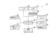
図1は、本発明の第1の実施形態にかかる車両の走行制御装置10が適用された車両を模式的に示す説明図である。この車両の走行制御装置10は、車両が障害物に接触することを回避するために車両の運動状態の制御(走行制御)を行う装置であり、検出系、コントローラ30およびアクチュエータ40,41を主体に構成されている。
(First embodiment)
FIG. 1 is an explanatory diagram schematically showing a vehicle to which a vehicle travel control device 10 according to a first embodiment of the present invention is applied. This vehicle travel control device 10 is a device for controlling the vehicle motion state (running control) in order to avoid the vehicle from coming into contact with an obstacle, and mainly comprises a detection system, a controller 30 and actuators 40 and 41. It is configured.

レーダ20は、車両の進行方向における物体までの距離および位置を検出する。レーダ20としては、レーザレーダやミリ波レーダなどを用いることができる。例えば、レーダ20としてレーザレーダを用いた場合、このレーダ20は、車両前方にレーザ光を照射し、前方に存在する物体からの反射光を受光系で受光する。そして、レーダ20は、レーザ発射時点と反射光の受光時点との時間差を検出することにより、車両と物体との間の距離および位置を検出する。   The radar 20 detects the distance and position to the object in the traveling direction of the vehicle. As the radar 20, a laser radar, a millimeter wave radar, or the like can be used. For example, when a laser radar is used as the radar 20, the radar 20 irradiates laser light in front of the vehicle and receives reflected light from an object existing in front by a light receiving system. The radar 20 detects the distance and position between the vehicle and the object by detecting the time difference between the laser emission time and the reflected light reception time.

カメラ21は、車両前方を撮像することにより、撮像画像を画像処理装置22に出力する。画像処理装置22は、カメラ21からの撮像画像を処理することにより、前方に存在する物体や道路環境等の走行環境情報を検出する。   The camera 21 outputs a captured image to the image processing device 22 by imaging the front of the vehicle. The image processing device 22 processes the captured image from the camera 21 to detect traveling environment information such as an object existing ahead and a road environment.

ヨーレートセンサ23は、車両1に発生するヨーレートを検出する。Gセンサ24は、車両の前後方向(車長方向)の加速度(以下「前後加速度」という)を検出するとともに、車両の横方向(車幅方向)の加速度(以下「横加速度」という)を検出する。車輪速センサ25は、車両1の各車輪の回転速度を検出することにより、車両の速度(車速)を検出する。   The yaw rate sensor 23 detects the yaw rate generated in the vehicle 1. The G sensor 24 detects acceleration in the longitudinal direction (vehicle length direction) of the vehicle (hereinafter referred to as “longitudinal acceleration”) and also detects acceleration in the lateral direction (vehicle width direction) of the vehicle (hereinafter referred to as “lateral acceleration”). To do. The wheel speed sensor 25 detects the speed (vehicle speed) of the vehicle by detecting the rotational speed of each wheel of the vehicle 1.

操舵角センサ26は、運転者が操作するハンドルの回転角を操舵角として検出する。この操舵角は、直進走行に対応するハンドルの中立状態を基準として、左方向または右方向といった操舵方向とともに操舵角を検出する。操舵トルクセンサ27は、運転者のハンドル操作によって加えられる操舵トルクを検出する。この操舵トルクは、直進走行に対応するハンドルの中立状態を基準として、左方向または右方向といった操舵方向とともに操舵トルクを検出する。   The steering angle sensor 26 detects the rotation angle of the handle operated by the driver as the steering angle. The steering angle is detected together with the steering direction such as the left direction or the right direction with reference to the neutral state of the handle corresponding to the straight traveling. The steering torque sensor 27 detects the steering torque applied by the driver's steering operation. The steering torque is detected together with the steering direction such as the left direction or the right direction with reference to the neutral state of the handle corresponding to the straight traveling.

図2は、コントローラ30の機能的な構成を示すブロック図である。コントローラ30は、システム全体を統合的に制御する機能を担っており、制御プログラムに従って動作することにより、障害物を回避するための走行制御を行う。コントローラ30としては、CPU、ROM、RAM、I/Oインターフェースを主体に構成されたマイクロコンピュータを用いることができる。このコントローラ30は、検出系によって検出される各種の情報に基づいて、種々の演算を行い、この演算結果に応じた制御信号をアクチュエータ40,41に出力することにより、車両の運動状態の制御(走行制御)を行う。   FIG. 2 is a block diagram illustrating a functional configuration of the controller 30. The controller 30 has a function of controlling the entire system in an integrated manner, and performs traveling control for avoiding obstacles by operating according to the control program. As the controller 30, a microcomputer mainly composed of a CPU, a ROM, a RAM, and an I / O interface can be used. The controller 30 performs various calculations based on various types of information detected by the detection system, and outputs a control signal corresponding to the calculation result to the actuators 40 and 41, thereby controlling the motion state of the vehicle ( Run control).

コントローラ30は、これを機能的に捉えた場合、障害物検出部31、運動状態検出部32、運転操作検出部33、回避軌道生成部34、回避軌道選択部35、リスク演算部36、制御抑制部37、操舵反力調整部38および走行制御部39を有している。   When the controller 30 grasps this functionally, the obstacle detection unit 31, the movement state detection unit 32, the driving operation detection unit 33, the avoidance trajectory generation unit 34, the avoidance trajectory selection unit 35, the risk calculation unit 36, the control suppression Part 37, steering reaction force adjusting part 38, and travel control part 39.

障害物検出部31は、レーダ20から検出信号を読み込むとともに、画像処理装置22から処理結果を読み込む。障害物検出部31は、読み込んだ情報に基づいて、自車両と接触する可能性のある物体を障害物として検出する(障害物検出手段)。障害物検出部31による検出結果は、回避軌道生成部34、リスク演算部36および制御抑制部37にそれぞれ出力される。   The obstacle detection unit 31 reads a detection signal from the radar 20 and reads a processing result from the image processing device 22. The obstacle detection unit 31 detects an object that may come into contact with the host vehicle as an obstacle based on the read information (obstacle detection means). The detection result by the obstacle detection unit 31 is output to the avoidance trajectory generation unit 34, the risk calculation unit 36, and the control suppression unit 37, respectively.

運動状態検出部32は、ヨーレートセンサ23、Gセンサ24および車輪速センサ25から検出信号をそれぞれ読み込む。運動状態検出部32は、読み込んだ各情報から車両の運動状態を検出する(運動状態検出手段)。運動状態検出部32による検出結果は、回避軌道生成部34およびリスク演算部36にそれぞれ出力される。   The motion state detection unit 32 reads detection signals from the yaw rate sensor 23, the G sensor 24, and the wheel speed sensor 25, respectively. The motion state detection unit 32 detects the motion state of the vehicle from each read information (motion state detection means). The detection result by the movement state detection unit 32 is output to the avoidance trajectory generation unit 34 and the risk calculation unit 36, respectively.

運転操作検出部33は、操舵角センサ26および操舵トルクセンサ27から検出信号をそれぞれ読み込む。運転操作検出部33は、読み込んだ情報に基づいて、運転者による運転操作を検出する(運転操作検出手段)。運転操作検出部33による検出結果は、回避軌道選択部35および操舵反力調整部38に対してそれぞれ出力される。   The driving operation detection unit 33 reads detection signals from the steering angle sensor 26 and the steering torque sensor 27, respectively. The driving operation detection unit 33 detects a driving operation by the driver based on the read information (driving operation detection means). The detection result by the driving operation detection unit 33 is output to the avoidance trajectory selection unit 35 and the steering reaction force adjustment unit 38, respectively.

回避軌道生成部34は、障害物の検出結果と車両の運動状態とに基づいて、障害物との接触を回避するための回避軌道を複数生成する(回避軌道生成手段)。回避軌道生成部34によって生成された複数の回避軌道は、回避軌道選択部35に出力される。   The avoidance trajectory generation unit 34 generates a plurality of avoidance trajectories for avoiding contact with the obstacle based on the obstacle detection result and the vehicle motion state (avoidance trajectory generation means). The multiple avoidance trajectories generated by the avoidance trajectory generation unit 34 are output to the avoidance trajectory selection unit 35.

回避軌道選択部35は、運転者の運転操作に基づいて、生成された複数の回避軌道のなかから、運転者の運転操作に適合する回避軌道を選択する(回避軌道選択手段)。回避軌道選択部35によって選択された回避軌道は、リスク演算部36、操舵反力調整部38および走行制御部39にそれぞれ出力される。   The avoidance trajectory selection unit 35 selects an avoidance trajectory that matches the driving operation of the driver from among the plurality of avoidance trajectories generated based on the driving operation of the driver (avoidance trajectory selection means). The avoidance trajectory selected by the avoidance trajectory selection unit 35 is output to the risk calculation unit 36, the steering reaction force adjustment unit 38, and the travel control unit 39, respectively.

リスク演算部36は、障害物の検出結果と車両の運動状態とに基づいて、リスクを演算する(リスク演算手段)。このリスクは、自車両の進行方向(回避軌道)と略直交方向(以下「軌道直交方向」という)に延在する所定範囲における障害物との接触可能性を示す指標である。本実施形態において、リスク演算部36は、回避軌道選択部35によって選択された回避軌道に対応して、リスクを演算する。リスク演算部36によって演算された回避軌道に対応するリスクは、制御抑制部37に対して出力される。   The risk calculation unit 36 calculates a risk based on the obstacle detection result and the vehicle motion state (risk calculation means). This risk is an index indicating the possibility of contact with an obstacle in a predetermined range extending in a direction substantially orthogonal to the traveling direction of the host vehicle (avoidance track) (hereinafter referred to as “track orthogonal direction”). In the present embodiment, the risk calculation unit 36 calculates a risk corresponding to the avoidance trajectory selected by the avoidance trajectory selection unit 35. The risk corresponding to the avoidance trajectory calculated by the risk calculation unit 36 is output to the control suppression unit 37.

制御抑制部37は、演算されたリスクと、障害物の検出結果とに基づいて、制御抑制量を演算する(抑制手段)。制御抑制量は、後述する走行制御部39が、選択された回避軌道に追従するための走行制御を行う場合において、これを抑制するために必要な制御量である。制御抑制部37によって演算された制御抑制量は、走行制御部39に対して出力される。   The control suppression unit 37 calculates a control suppression amount based on the calculated risk and the obstacle detection result (a suppression unit). The control suppression amount is a control amount necessary to suppress this when the travel control unit 39 described later performs travel control for following the selected avoidance path. The control suppression amount calculated by the control suppression unit 37 is output to the travel control unit 39.

操舵反力調整部38は、選択された回避軌道に対する自車両の走行状況に応じて、運転者の操舵操作に対する操舵反力を調整する(操舵反力調整手段)。具体的には、操舵反力調整部38は、選択された回避軌道に対する自車両の走行状況に応じた操舵反力を付与するための制御量を演算する。   The steering reaction force adjusting unit 38 adjusts the steering reaction force for the steering operation of the driver according to the traveling state of the host vehicle with respect to the selected avoidance track (steering reaction force adjusting means). Specifically, the steering reaction force adjusting unit 38 calculates a control amount for applying a steering reaction force according to the traveling state of the host vehicle with respect to the selected avoidance track.

走行制御部39は、選択された回避軌道と、制御抑制部37によって演算された制御抑制量と、操舵反力調整部38によって演算された制御量とに基づいて、選択された回避軌道を自車両が走行するための走行制御量を演算する。そして、走行制御部39は、走行制御量に基づいて、アクチュエータ40,41を制御することにより、走行制御、すなわち、車両の運動状態を制御する(走行制御手段)。   The traveling control unit 39 automatically selects the avoidance trajectory selected based on the selected avoidance trajectory, the control suppression amount calculated by the control suppression unit 37, and the control amount calculated by the steering reaction force adjustment unit 38. A travel control amount for the vehicle to travel is calculated. Then, the travel control unit 39 controls the actuators 40 and 41 based on the travel control amount to control the travel control, that is, the motion state of the vehicle (travel control means).

操舵アクチュエータ40は、車輪に横力を付与する(すなわち、車両に横加速度を付与する)アクチュエータであり、例えば、運転者の操舵をアシストするアシストトルクを付与するアシストモータも含む。この操舵アクチュエータ40は、車輪に任意の操舵角を付与させて車両の操舵動作を行うことができるとともに、運転者に対する操舵反力を調整することができる。   The steering actuator 40 is an actuator that applies lateral force to the wheels (that is, applies lateral acceleration to the vehicle), and includes, for example, an assist motor that applies assist torque that assists the driver's steering. The steering actuator 40 can perform a steering operation of the vehicle by giving an arbitrary steering angle to the wheels, and can adjust a steering reaction force to the driver.

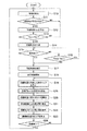
図3は、第1の実施形態にかかる走行制御方法を示すフローチャートである。このフローチャートに示す処理は、車両のイグニッションスイッチがオンされると呼び出され、所定の周期でコントローラ30によって実行される。   FIG. 3 is a flowchart illustrating the travel control method according to the first embodiment. The process shown in this flowchart is called when the ignition switch of the vehicle is turned on, and is executed by the controller 30 at a predetermined cycle.

ステップ10(S10)において、障害物検出部31は、レーダ20と画像処理装置22とからの入力情報に基づいて、車両が走行可能な領域(以下「走行路」という)と、走行路内に存在する物体とを検出する。なお、走行路等の検出方法は本願の出願時点で既に公知であるので詳細な説明は省略する。走行路の検出方法については、例えば、特許第3521860号公報に開示されているので、必要ならば参照されたい。   In step 10 (S10), the obstacle detection unit 31 includes an area in which the vehicle can travel (hereinafter referred to as “traveling road”) and a traveling path based on input information from the radar 20 and the image processing device 22. Detects existing objects. Note that a method for detecting a traveling road or the like is already known at the time of filing of the present application, and thus detailed description thereof is omitted. About the detection method of a traveling path, since it is disclosed by the patent 3521860 gazette, please refer if necessary.

ステップ11(S11)において、障害物検出部31は、ステップ10における検出結果に基づいて、車両と接触する可能性がある物体(以下「障害物」という)が走行路内に存在するか否かを判別する。なお、障害物の検出方法は本願の出願時点で既に公知であるので詳細な説明を省略する。障害物の検出方法については、例えば、特開2000−207693号公報に開示されているので、必要ならば参照されたい。このステップ11において肯定判定された場合、すなわち、障害物が存在する場合には、ステップ12(S12)に進む。一方、ステップ11において否定判定された場合、すなわち、障害物が存在しない場合には、ステップ10の処理に戻る。   In step 11 (S11), the obstacle detection unit 31 determines based on the detection result in step 10 whether or not there is an object (hereinafter referred to as “obstacle”) that may come into contact with the vehicle in the travel path. Is determined. In addition, since the detection method of an obstruction is already well-known at the time of the application of this application, detailed description is abbreviate | omitted. The obstacle detection method is disclosed in, for example, Japanese Patent Application Laid-Open No. 2000-207693, so refer to it if necessary. If an affirmative determination is made in step 11, that is, if there is an obstacle, the process proceeds to step 12 (S12). On the other hand, if a negative determination is made in step 11, that is, if there is no obstacle, the process returns to step 10.

ステップ12において、障害物検出部31は、障害物と自車両との間の距離および障害物と自車両との相対速度に基づいて、ステップ11の処理により確認された障害物に自車両が接触するまでの時間を接触予測時間Tttcとして算出する。障害物と自車両との間の距離はレーダ20からの入力情報により算出でき、自車両と障害物の相対速度は例えば算出された距離を時間微分することによって算出することができる。   In step 12, the obstacle detection unit 31 makes contact with the obstacle confirmed by the processing in step 11 based on the distance between the obstacle and the own vehicle and the relative speed between the obstacle and the own vehicle. The time until this is calculated as the predicted contact time Tttc. The distance between the obstacle and the host vehicle can be calculated from input information from the radar 20, and the relative speed between the host vehicle and the obstacle can be calculated by, for example, differentiating the calculated distance with time.

ステップ13(S13)において、回避軌道生成部34は、接触予測時間Tttcが予め設定された第1の判定時間Tth1以下であるか否かを判別する。このステップ13において肯定判定された場合、すなわち、接触予測時間Tttcが第1の判定時間Tth1以下である場合には、ステップ14(S14)に進む。一方、ステップ13において否定判定された場合、すなわち、接触予測時間Tttcが第1の判定時間Tth1以下でない場合には、ステップ10の処理に戻る。   In step 13 (S13), the avoidance trajectory generation unit 34 determines whether or not the predicted contact time Tttc is equal to or shorter than a preset first determination time Tth1. If an affirmative determination is made in step 13, that is, if the predicted contact time Tttc is equal to or shorter than the first determination time Tth1, the process proceeds to step 14 (S14). On the other hand, if a negative determination is made in step 13, that is, if the predicted contact time Tttc is not equal to or shorter than the first determination time Tth1, the process returns to step 10.

接触予測時間Tttcが第1の判定時間Tth1以下でない場合、換言すれば、自車両が障害物に接触するまでの時間が比較的長い場合には、一般に、その後の運転者による車両操作によって障害物との接触が回避される可能性がある。したがって、接触を回避するための走行制御を実行する必要性がなくなる可能性が高い。これより、走行制御を実行する必要性がないようなシーンであるにも係わらず、後述する走行制御が実行されることを抑制する。そのため、コントローラ30の処理負荷の低減を図ることができる。そのため、ステップ13の判定処理では、このような判断を行うための第1の判定時間Tth1が、実験やシミュレーションを通じて設定されている。   If the predicted contact time Tttc is not less than or equal to the first determination time Tth1, in other words, if the time until the host vehicle is in contact with the obstacle is relatively long, the obstacle is generally caused by subsequent vehicle operation by the driver. May be avoided. Therefore, there is a high possibility that there is no need to execute travel control for avoiding contact. As a result, it is possible to suppress the execution of travel control, which will be described later, even though the scene does not require execution of travel control. Therefore, the processing load on the controller 30 can be reduced. Therefore, in the determination process in step 13, the first determination time Tth1 for making such a determination is set through experiments and simulations.

ステップ14において、回避軌道生成部34は、検出された障害物と、検出された自車両の運動状態とに基づいて、障害物との接触を回避するための走行軌道を回避軌道として複数生成(算出)する。本実施形態において、回避軌道生成部34は、操舵によって障害物との接触を回避する回避軌道をそれぞれ生成する。具体的には、図4に示すように、左方向への操舵によって障害物との接触を回避する回避軌道R1と、右方向への操舵によって障害物との接触を回避する回避軌道R2とをそれぞれ生成する。同図において、「C」は自車両を示し、「O」は矢印方向(軌道直交方向)に移動する障害物を示す。   In step 14, the avoidance trajectory generation unit 34 generates a plurality of travel trajectories as avoidance trajectories for avoiding contact with the obstacle based on the detected obstacle and the detected motion state of the host vehicle. calculate. In the present embodiment, the avoidance trajectory generation unit 34 generates an avoidance trajectory that avoids contact with an obstacle by steering. Specifically, as shown in FIG. 4, an avoidance trajectory R1 that avoids contact with an obstacle by steering in the left direction and an avoidance trajectory R2 that avoids contact with the obstacle by steering in the right direction. Generate each. In the figure, “C” indicates the own vehicle, and “O” indicates an obstacle moving in the direction of the arrow (direction perpendicular to the track).

個々の回避軌道R1,R2を生成する場合、回避軌道生成部34は、自車両の運動状態と自車両のタイヤ特性とに基づいて、障害物との接触を回避するために自車両に付与すべき横加速度を設定する。そして、回避軌道生成部34は、設定された横加速度によって障害物との接触を回避できるか否かを判断する。回避軌道生成部34は、横加速度により接触を回避可能と判断した場合には、当該横加速度に対応する回避軌道を走行路の範囲内で算出する。この場合、回避軌道生成部34は、走行路の範囲から外れる回避軌道は生成しない。一方、回避軌道生成部34は、横加速度により接触を回避できないと判断した場合には、回避軌道を生成しない。   When generating the individual avoidance tracks R1 and R2, the avoidance track generation unit 34 assigns the avoidance track generation unit 34 to the own vehicle in order to avoid contact with an obstacle based on the motion state of the own vehicle and the tire characteristics of the own vehicle. Set the lateral acceleration. Then, the avoidance trajectory generation unit 34 determines whether or not contact with an obstacle can be avoided by the set lateral acceleration. When the avoidance trajectory generation unit 34 determines that the contact can be avoided by the lateral acceleration, the avoidance trajectory generation unit 34 calculates an avoidance trajectory corresponding to the lateral acceleration within the range of the travel path. In this case, the avoidance trajectory generation unit 34 does not generate an avoidance trajectory that is out of the range of the travel path. On the other hand, the avoidance trajectory generation unit 34 does not generate an avoidance trajectory when it is determined that contact cannot be avoided due to the lateral acceleration.

ステップ15(S15)において、回避軌道選択部35は、運転者による何らかの操作があったか否かを判断する。回避軌道選択部35は、運転操作検出部33において検出される操作量、具体的には、操舵角を参照して、運転者による操舵操作が行われたか否かを判断する。操舵操作の有無の判断方法は、例えば、ステップ14において回避軌道が算出されたタイミングにおける操舵角から、左右いずれの方向に操舵角が変化したか否かを検出するといった如くである。また、単に操舵方向だけでなく、回避軌道が算出されたタイミングにおける操舵角を基準として、操舵角変化が所定のしきい値以上生じたか否かを判断してもよい。さらに、操舵角変化の代わりに、操舵角速度または操舵角加速度が所定のしきい値以上変化したことを判断してもよい。このステップ15において否定判定された場合、すなわち、運転者による操作がない場合には、ステップ16(S16)に進む。一方、ステップ15において肯定判定された場合、すなわち、運転者による操作があった場合には、ステップ17(S17)に進む。   In step 15 (S15), the avoidance trajectory selection unit 35 determines whether or not there is any operation by the driver. The avoidance trajectory selection unit 35 refers to the operation amount detected by the driving operation detection unit 33, specifically, the steering angle, and determines whether or not a steering operation by the driver has been performed. The method for determining the presence or absence of the steering operation is, for example, detecting whether the steering angle has changed in either the left or right direction from the steering angle at the timing at which the avoidance trajectory was calculated in step 14. Further, it may be determined whether or not a change in the steering angle has occurred by a predetermined threshold value or more based not only on the steering direction but also on the steering angle at the timing when the avoidance track is calculated. Further, instead of the change in the steering angle, it may be determined that the steering angular velocity or the steering angular acceleration has changed by a predetermined threshold value or more. If a negative determination is made in step 15, that is, if there is no operation by the driver, the process proceeds to step 16 (S16). On the other hand, if an affirmative determination is made in step 15, that is, if there is an operation by the driver, the process proceeds to step 17 (S17).

ステップ16において、回避軌道選択部35は、ステップ12の処理により算出された接触予測時間Tttcが、接触予測時間Tth2以上であるか否かを判断する。ここで、図4の地点P1,P2に示すように、各回避軌道に追従する走行制御を行うための制御開始地点は、回避軌道に応じて異なる。上述の接触予測時間Tth2は、制御開始地点が障害物から最も近い位置となる回避軌道について、その制御開始地点に車両が到達した際の接触予測時間である(図4に示す例では、地点P2における接触予測時間)。このステップ16において肯定判定された場合、すなわち、接触予測時間Tttcが接触予測時間Tth2以上である場合には、ステップ15の処理に戻る。一方、ステップ16において否定判定された場合、すなわち、接触予測時間Tttcが接触予測時間Tth2よりも小さい場合には、ステップ17の処理に進む。   In step 16, the avoidance trajectory selection unit 35 determines whether or not the predicted contact time Tttc calculated by the processing in step 12 is equal to or longer than the predicted contact time Tth2. Here, as shown at points P1 and P2 in FIG. 4, the control start point for performing the traveling control following each avoidance track differs depending on the avoidance track. The predicted contact time Tth2 described above is the predicted contact time when the vehicle arrives at the control start point of the avoidance trajectory where the control start point is closest to the obstacle (in the example shown in FIG. 4, the point P2 Predicted contact time). If an affirmative determination is made in step 16, that is, if the predicted contact time Tttc is greater than or equal to the predicted contact time Tth2, the process returns to step 15. On the other hand, if a negative determination is made in step 16, that is, if the predicted contact time Tttc is smaller than the predicted contact time Tth2, the process proceeds to step 17.

ステップ17において、回避軌道選択部35は、生成されている複数の回避軌道のなかから、回避軌道を選択する。具体的には、回避軌道選択部35は、運転者によって操作が行われている場合には、複数の回避軌道R1,R2の中から、運転者の操作に適合する回避軌道を選択する。例えば、運転者によって右方向の操舵が行われている場合には、右方向の操舵に適合する回避軌道R2を選択するといった如くである。一方、運転者によって操作が行われていない場合には、運転者が操作を開始する地点が、いずれの回避軌道R1,R2に関する制御開始地点P1,P2よりも障害物に近い状態となる。そこで、回避軌道選択部35は、複数の回避軌道R1,R2の中から、制御開始地点P1,P2が最も障害物に近い回避軌道を選択する。   In step 17, the avoidance trajectory selection unit 35 selects an avoidance trajectory from among the plurality of avoidance trajectories that have been generated. Specifically, when the operation is performed by the driver, the avoidance trajectory selection unit 35 selects an avoidance trajectory that matches the driver's operation from the plurality of avoidance trajectories R1 and R2. For example, when the driver is steering in the right direction, the avoidance track R2 that matches the steering in the right direction is selected. On the other hand, when the operation is not performed by the driver, the point at which the driver starts the operation is closer to the obstacle than the control start points P1 and P2 regarding any of the avoidance tracks R1 and R2. Therefore, the avoidance trajectory selection unit 35 selects an avoidance trajectory whose control start points P1 and P2 are closest to the obstacle from the plurality of avoidance trajectories R1 and R2.

ステップ18(S18)において、走行制御部39は、選択された回避軌道に基づいて、走行制御を開始する。具体的には、走行制御部39は、走行制御部39は、操舵アクチュエータ40の制御を開始する。   In step 18 (S18), the traveling control unit 39 starts traveling control based on the selected avoidance track. Specifically, the travel control unit 39 starts the control of the steering actuator 40.

ステップ19(S19)において、走行制御部39は、選択された回避軌道に基づいて、例えば2輪モデルを用いて、車両が回避軌道に追従するための目標操舵角を算出する。そして、走行制御部39は、目標操舵角と現在の操舵角との偏差(操舵角偏差)を検知し、この操舵角偏差を減少させるための制御量として、操舵アクチュエータ40に対する指令トルクを算出する。なお、目標操舵角に追従するような指令トルクの算出方法に関して、様々な方法が挙げられ、本願の出願時点で既に公知であるので詳細な説明を省略する。なお、目標操舵角の算出方向は、選択された回避軌道から、車両のヨーレートセンサ23と車輪速センサ25からの入力情報のみを利用して、目標操舵角を近似的に算出してもよい。また、選択された回避軌道は、最初から目標操舵角であってもよい。   In step 19 (S19), the travel control unit 39 calculates a target steering angle for the vehicle to follow the avoidance track using, for example, a two-wheel model, based on the selected avoidance track. Then, the traveling control unit 39 detects a deviation (steering angle deviation) between the target steering angle and the current steering angle, and calculates a command torque for the steering actuator 40 as a control amount for reducing the steering angle deviation. . There are various methods for calculating the command torque to follow the target steering angle, and since they are already known at the time of filing of the present application, detailed description thereof is omitted. Note that the target steering angle may be calculated approximately from the selected avoidance trajectory using only the input information from the yaw rate sensor 23 and the wheel speed sensor 25 of the vehicle. Further, the selected avoidance trajectory may be the target steering angle from the beginning.

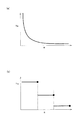
ステップ20(S20)において、リスク演算部36は、障害物の検出結果および車両の運動状態の検出結果に基づいて、選択された回避経路に対応するリスクを演算する。このリスクは、上述した通り、軌道直交方向に延在する所定範囲における障害物との接触可能性を示す指標であり、前方に障害物がない範囲において小さい値となり、前方に障害物がある範囲において大きい値となるように設定される。例えば、正規化したリスクを用いた場合、障害物がない範囲におけるリスクは0が設定され、障害物がある範囲におけるリスクは1が設定される。その間の範囲においては、例えば、図7(a),(b)に示すように、「0」と「1」との間を適宜に結ぶようにリスクを設定してもよい。   In step 20 (S20), the risk calculation unit 36 calculates a risk corresponding to the selected avoidance route based on the detection result of the obstacle and the detection result of the motion state of the vehicle. As described above, this risk is an index indicating the possibility of contact with an obstacle in a predetermined range extending in the direction orthogonal to the trajectory, and is a small value in a range where there is no obstacle ahead, and a range where there is an obstacle ahead. Is set to a large value. For example, when the normalized risk is used, 0 is set for the risk in the range without the obstacle, and 1 is set for the risk in the range with the obstacle. In the range between them, for example, as shown in FIGS. 7A and 7B, the risk may be set so as to appropriately connect “0” and “1”.

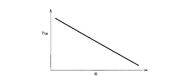
ステップ21(S21)において、制御抑制部37は、障害物検出部31の検出結果を利用して、障害物に対する車両の相対位置を算出する。そして、制御抑制部37は、演算したリスクの位置関係と比較して現在のリスクを求め、このリスクに基づいて制御量、具体的には、ステップ19で算出した指令トルクに対する補正量(具体的には、ステップ19の指令トルクを抑制するための補正量)を算出する。具体的には、制御抑制部37は、リスクが低い程、目標操舵角へ追従する指令トルクが弱くなるように、指令トルクに対する補正量を大きく算出する。これにより、リスクが低いシーンでは、運転者は車両の軌道を自ら修正可能となる。一方、制御抑制部37は、リスクが高い程、目標操舵角へ追従する指令トルクが弱くならないように、指令トルクに対する補正量を小さく算出する。リスクが高いシーンでは、運転者は車両の軌道を修正することが困難となる。このような観点から、指令トルクに対する補正量は、リスクの増加に応じて小さくなるような関係に設定されている。例えば、図6に示すように、指令トルクに対する補正量(Tta)は、リスク(R)に応じて線形的に変化するようなものであってもよい。また、図7(a)に示すように、指令トルクに対する補正量(Tta)は、リスク(R)に応じて非線形的に変化するが、反比例的に変化することで、上述の条件を満たすものであってもよい。また、図7(b)に示すように、指令トルクに対する補正量(Tta)は、あるリスク(R)の範囲では一定の補正量であるが、これがリスクの増加とともに段階的に小さくなるようなものであってもよい。   In step 21 (S21), the control suppression unit 37 calculates the relative position of the vehicle with respect to the obstacle using the detection result of the obstacle detection unit 31. Then, the control suppression unit 37 obtains the current risk by comparing with the calculated risk positional relationship, and based on this risk, the control amount, specifically, the correction amount for the command torque calculated in step 19 (specifically In step S19, a correction amount for suppressing the command torque in step 19 is calculated. Specifically, the control suppression unit 37 calculates a larger correction amount for the command torque so that the lower the risk, the weaker the command torque that follows the target steering angle. As a result, in a low-risk scene, the driver can correct the trajectory of the vehicle. On the other hand, the control suppression unit 37 calculates a smaller correction amount for the command torque so that the command torque that follows the target steering angle does not become weaker as the risk increases. In a high-risk scene, it is difficult for the driver to correct the vehicle trajectory. From such a viewpoint, the correction amount with respect to the command torque is set so as to decrease as the risk increases. For example, as shown in FIG. 6, the correction amount (Tta) for the command torque may be linearly changed according to the risk (R). Further, as shown in FIG. 7A, the correction amount (Tta) for the command torque changes nonlinearly according to the risk (R), but satisfies the above condition by changing inversely. It may be. Further, as shown in FIG. 7B, the correction amount (Tta) for the command torque is a constant correction amount within a certain risk (R) range, but this gradually decreases as the risk increases. It may be a thing.

ステップ22(S22)において、操舵反力調整部38は、選択された回避軌道に対する車両の追従状況を運転者に認識させるべく、ステップ19で算出した指令トルクに対する補正量(具体的には、操舵反力を調整するための補正量(制御量))を算出する。通常に、走行制御部39は、車輪の操舵角が目標操舵角と対応した時の回転位置を基準位置として、この基準位置からの操舵角の増加に応じて操舵反力が増加するように操舵反力を制御している。操舵反力調整部38は、ステップ19の演算における目標操舵角に対して現在の操舵角の偏差(操舵角偏差)が大きい程、基準位置からの操舵角の増加に応じた操舵反力の増加量が通常時よりも大きくなるように補正量を演算する。これにより、操舵角偏差が大きい場合には、選択された回避軌道から外れることを運転者に認識させることができる。一方、操舵角偏差が小さい場合には、操舵反力が通常時のそれと比較して大きくなりすぎることがない。そのため、運転者に自由な操舵操作を許容できるので、運転者が覚える違和感を低減することができる。このような観点から、操舵反力は、車輪の操舵角が目標操舵角と対応した時の回転位置を基準位置として、目標操舵角に対する偏差に対し比例関係となるように設定されている。例えば、図8に示すように、操舵反力は、目標操舵角の偏差に応じて線形的に変化するような関係であってもよい。   In step 22 (S22), the steering reaction force adjusting unit 38 corrects the command torque calculated in step 19 (specifically, the steering torque) so that the driver can recognize the vehicle follow-up state with respect to the selected avoidance track. A correction amount (control amount) for adjusting the reaction force is calculated. Normally, the travel control unit 39 uses the rotation position when the wheel steering angle corresponds to the target steering angle as a reference position, and steers the steering reaction force so that the steering reaction force increases as the steering angle increases from the reference position. The reaction force is controlled. The steering reaction force adjusting unit 38 increases the steering reaction force in accordance with the increase in the steering angle from the reference position as the deviation of the current steering angle (steering angle deviation) with respect to the target steering angle in the calculation of step 19 increases. The correction amount is calculated so that the amount is larger than normal. As a result, when the steering angle deviation is large, the driver can be recognized to be out of the selected avoidance track. On the other hand, when the steering angle deviation is small, the steering reaction force does not become too large compared to that in the normal state. As a result, the driver can be allowed to perform a free steering operation, so that the driver feels uncomfortable. From this point of view, the steering reaction force is set to be proportional to the deviation with respect to the target steering angle, with the rotational position when the steering angle of the wheel corresponds to the target steering angle as a reference position. For example, as shown in FIG. 8, the steering reaction force may be in a relationship that changes linearly according to the deviation of the target steering angle.

ステップ23(S23)において、走行制御部39は、ステップ19において演算された指令トルクと、ステップ21,22においてそれぞれ演算された補正量とに基づいて、最終的な指令トルクを算出する。具体的には、走行制御部39は、指令トルクと、各補正量とを加算することにより、最終的な指令トルクを演算する。そして、走行制御部39は、最終的な指令トルクから、アシストモータを駆動するために必要な指令電流に変換し、これを制御指令として操舵アクチュエータ40に出力する。操舵アクチュエータ40が制御指令に応じて動作することにより、操舵制御が行われる。   In step 23 (S23), the travel control unit 39 calculates a final command torque based on the command torque calculated in step 19 and the correction amounts calculated in steps 21 and 22, respectively. Specifically, the traveling control unit 39 calculates the final command torque by adding the command torque and each correction amount. Then, the travel control unit 39 converts the final command torque into a command current necessary for driving the assist motor, and outputs this to the steering actuator 40 as a control command. Steering control is performed by the steering actuator 40 operating according to the control command.

ステップ24(S24)において、障害物検出部31は、障害物に対する回避が終了し、障害物との接触の可能性がなくなったか否かを判断する。このステップ24において肯定判定をされた場合、すなわち、接触の可能性が無いと判断された場合には、ステップ10へ戻る。この場合、走行制御部39は、回避軌道選択部35が選択した回避軌道に車両を追従させる走行制御を終了する。一方、ステップ24において否定判定をされた場合、すなわち、接触の可能性があると判断された場合には、ステップ19に示す処理に戻る。   In step 24 (S24), the obstacle detection unit 31 determines whether or not the avoidance of the obstacle has been completed and the possibility of contact with the obstacle has disappeared. If an affirmative determination is made in step 24, that is, if it is determined that there is no possibility of contact, the process returns to step 10. In this case, the travel control unit 39 ends the travel control for causing the vehicle to follow the avoidance track selected by the avoidance track selection unit 35. On the other hand, if a negative determination is made in step 24, that is, if it is determined that there is a possibility of contact, the process returns to step 19.

このように本実施形態において、リスク演算部36は、選択された回避軌道を処理対象として、回避軌道と略直交方向に延在する所定範囲における障害物との接触可能性をリスクとして演算する。また、制御抑制部37は、演算されるリスクに応じて、走行制御部39による走行制御を抑制する。また、操舵反力調整部38は、選択された回避軌道に対する自車両の走行状況(具体的には、操舵角偏差)に応じて、運転者の操舵操作に対する操舵反力を調整する。   As described above, in the present embodiment, the risk calculation unit 36 calculates the possibility of contact with an obstacle in a predetermined range extending in a direction substantially orthogonal to the avoidance trajectory as a risk, using the selected avoidance trajectory as a processing target. Moreover, the control suppression part 37 suppresses the traveling control by the traveling control part 39 according to the calculated risk. Further, the steering reaction force adjusting unit 38 adjusts the steering reaction force with respect to the driver's steering operation according to the traveling state (specifically, the steering angle deviation) of the host vehicle with respect to the selected avoidance track.

かかる構成によれば、実際の軌道と、選択した回避軌道とに偏差が生じていても、リスクが小さい場合には、制御抑制量が大きくなるので、走行制御による操舵介入量が小さくなる。そのため、運転者自身が認識する外界の状況に応じた運転者の操舵と、制御介入による操舵との間に生じるギャップが抑制される。これにより、運転者が覚える違和感の低減を図ることができる。また、このような違和感を低減した走行制御を行った場合でも、選択された回避軌道に対する自車両の走行状況に応じて、操舵反力を付与することで、ハンドルを介して運転者に回避軌道を認識させることができる。また、運転者の操作を違和感が小さい回避軌道に誘導して、運転者の操作介入量を増やすことができる。   According to this configuration, even if there is a deviation between the actual trajectory and the selected avoidance trajectory, the amount of control suppression increases when the risk is small, so the steering intervention amount due to travel control decreases. Therefore, a gap generated between the steering of the driver according to the external situation recognized by the driver and the steering by the control intervention is suppressed. Thereby, it is possible to reduce the uncomfortable feeling that the driver learns. Further, even when the travel control with such a sense of incongruity is performed, the avoidance trajectory is provided to the driver via the steering wheel by applying a steering reaction force according to the traveling state of the vehicle with respect to the selected avoidance trajectory. Can be recognized. In addition, the amount of intervention by the driver can be increased by guiding the driver's operation to an avoidance trajectory with a small discomfort.

また、本実施形態において、走行制御部39は、選択された回避軌道に基づいて、車両が回避軌道に追従するための目標操舵角を算出し、算出された目標操舵角と現在の車輪の操舵角との操舵角偏差を減少させるための指令トルク(制御量)を算出する。そして、走行制御部39は、この算出された指令トルクに基づいて、自車両を走行制御する。かかる構成によれば、偏差に対応する指令トルクを与えるため、指令トルクの絶対値を小さくすることができ、運転者が覚える違和感を低減することができる。また、制御抑制部37により走行制御が抑制された状態においては、車両は緩やかに選択された回避軌道に近づくことになる。このため、運転者は、操舵操作子(ハンドル)を介して、1本の目標とする回避軌道に向かって違和感なく誘導されていると感じ、安心感を得ることができる。   In the present embodiment, the travel control unit 39 calculates a target steering angle for the vehicle to follow the avoidance track based on the selected avoidance track, and the calculated target steering angle and the current wheel steering. A command torque (control amount) for reducing the steering angle deviation from the angle is calculated. Then, the traveling control unit 39 controls traveling of the host vehicle based on the calculated command torque. According to such a configuration, since the command torque corresponding to the deviation is applied, the absolute value of the command torque can be reduced, and the uncomfortable feeling that the driver learns can be reduced. Further, in a state where the travel control is suppressed by the control suppression unit 37, the vehicle approaches the avoidance track selected gently. For this reason, the driver feels that he / she is guided to the single avoidance track through the steering operator (steering wheel) without a sense of incongruity, and can obtain a sense of security.

また、本実施形態において、操舵反力調整部38は、操舵角偏差が大きい程、基準位置からの操舵角の増加に応じた操舵反力の増加がさらに大きくなるような調整を行っている。かかる構成によれば、運転者は、操舵反力から直感的に回避経路を認識することができる。そのため、運転者に違和感を覚えさせることなく、運転者の操作を回避軌道へ誘導することができる。また、操舵反力は目標操舵角からの偏差に応じて増加するため、運転者がパニックに陥ってしまうような状況であっても不要な操舵操作を抑制することができる。   In the present embodiment, the steering reaction force adjustment unit 38 performs an adjustment such that the greater the steering angle deviation, the greater the increase in the steering reaction force according to the increase in the steering angle from the reference position. According to this configuration, the driver can intuitively recognize the avoidance route from the steering reaction force. Therefore, the driver's operation can be guided to the avoidance path without making the driver feel uncomfortable. Further, since the steering reaction force increases in accordance with the deviation from the target steering angle, an unnecessary steering operation can be suppressed even in a situation where the driver panics.

なお、本実施形態では、ステップ10の処理において、走行路内に存在する物体を障害物として検出していたが、走行路内か否かを考慮せず、例えば自車両前方の所定の領域内に存在する物体を障害物として検出してもよい。   In the present embodiment, in the processing of step 10, an object present in the travel road is detected as an obstacle, but it is not considered whether it is in the travel road, for example, within a predetermined area in front of the host vehicle. May be detected as an obstacle.

また、ステップS14で操舵反力を算出するために、ステップ20において算出されるリスクを用いてもよい。この場合、リスクの低い範囲では、操舵反力を小さくし、またはパワーステアリング特性が持っている操舵反力に設定してもよい。一方、リスクの高い範囲では、操舵反力を非常に大きくし、運転者が操舵しにくくすることで、運転者のミスによる操舵操作を抑制するようにしてもよい。   Further, the risk calculated in step 20 may be used to calculate the steering reaction force in step S14. In this case, in a low risk range, the steering reaction force may be reduced or set to the steering reaction force possessed by the power steering characteristics. On the other hand, in a high-risk range, the steering reaction force may be made extremely large to make it difficult for the driver to steer, thereby suppressing the steering operation due to the driver's mistake.

(第2の実施形態)
図9は、第2の実施形態にかかる車両の走行制御装置10の構成を示すブロック図である。本実施形態にかかる車両の走行制御装置10およびその制御方法が、第1の実施形態のそれと相違する点は、走行制御として操舵制御のみならず制動制御を行うことである。なお、第1の実施形態と重複する説明は省略することとし、以下相違点を中心に説明を行う。本実施形態において、車両の走行制御装置10には、第1の実施形態に示す構成に加え、ブレーキアクチュエータ41が追加されている。ブレーキアクチュエータ41は、例えば、車両のホイールシリンダに供給される制動液圧を制御するアクチュエータであり、このブレーキアクチュエータ41を制御することにより、車輪に制動力を発生させて車両の制動動作を行うことができる。
(Second Embodiment)
FIG. 9 is a block diagram showing the configuration of the vehicle travel control apparatus 10 according to the second embodiment. The vehicle travel control device 10 and its control method according to this embodiment differ from those of the first embodiment in that not only steering control but also braking control is performed as travel control. In addition, the description which overlaps with 1st Embodiment shall be abbreviate | omitted, and it demonstrates focusing on difference below. In the present embodiment, a brake actuator 41 is added to the vehicle travel control device 10 in addition to the configuration shown in the first embodiment. The brake actuator 41 is, for example, an actuator that controls a brake fluid pressure supplied to a wheel cylinder of the vehicle. By controlling the brake actuator 41, a braking force is generated on the wheels to perform a braking operation of the vehicle. Can do.

図10は、第2の実施形態にかかる走行制御方法を示すフローチャートである。本実施形態の制御方法では、第1の実施形態と比較して、ステップ25(S25)の処理が、ステップ19の処理とステップ20の処理との間に追加的に実行される。   FIG. 10 is a flowchart illustrating a travel control method according to the second embodiment. In the control method of this embodiment, the process of step 25 (S25) is additionally executed between the process of step 19 and the process of step 20 as compared with the first embodiment.

ステップ25において、走行制御部39は、車両が目標操舵角に追従することで、障害物を回避するのに必要な横力やヨーレートに妨げない程度に、必要な減速度を設定する。走行制御部39は、設定された減速度に必要な液圧指令値を演算し、これを制御指令としてブレーキアクチュエータ41に出力する。ブレーキアクチュエータ41が制御指令に応じて動作することにより、制動制御が行われる。   In step 25, the traveling control unit 39 sets the necessary deceleration so that the vehicle does not obstruct the lateral force and yaw rate necessary to avoid the obstacle by following the target steering angle. The traveling control unit 39 calculates a hydraulic pressure command value necessary for the set deceleration, and outputs this to the brake actuator 41 as a control command. Braking control is performed by the brake actuator 41 operating in response to a control command.

このようの本実施形態によれば、制動制御を加えることにより、障害物を回避するための走行制御をより有効に行うことができる。   According to the present embodiment as described above, by applying the braking control, it is possible to more effectively perform the traveling control for avoiding the obstacle.

なお、ステップ25の処理では、ブレーキアクチュエータ41の液圧指令値をアクチュエータが許容する最大指令値値圧に設定しもよい。また、ブレーキアクチュエータ41の液圧指令値は減速をさせるために、ある一定値に設定してもよい。   In the process of step 25, the hydraulic pressure command value of the brake actuator 41 may be set to the maximum command value pressure allowed by the actuator. Further, the hydraulic pressure command value of the brake actuator 41 may be set to a certain constant value in order to decelerate.

(第3の実施形態)
第3の実施形態にかかる車両の走行制御装置10およびその制御方法が、第1の実施形態のそれと相違する点は、操舵反力を演算する際の手法である。なお、第1の実施形態と重複する説明は省略することとし、以下相違点を中心に説明を行う。本実施形態において、車両の走行制御装置10の構成は、第1の実施形態と同様である。
(Third embodiment)
The vehicle travel control apparatus 10 and its control method according to the third embodiment are different from those of the first embodiment in a method for calculating a steering reaction force. In addition, the description which overlaps with 1st Embodiment shall be abbreviate | omitted, and it demonstrates focusing on difference below. In the present embodiment, the configuration of the vehicle travel control device 10 is the same as that of the first embodiment.

図11は、第3の実施形態にかかる走行制御方法を示すフローチャートである。本実施形態の制御方法では、第1の実施形態と比較して、ステップ26(S26)の処理が追加されており、この処理がステップ19からステップ21までの処理と並列的に実行される。   FIG. 11 is a flowchart illustrating a travel control method according to the third embodiment. In the control method of this embodiment, the process of step 26 (S26) is added compared with 1st Embodiment, This process is performed in parallel with the process from step 19 to step 21. FIG.

ステップ26(S26)において、走行制御部39は、運転操作検出部33によって検出される操舵トルクセンサ27からの入力情報を利用して、運転者の操舵状況に応じて操舵反力を調整する。具体的に、操舵トルクセンサ27によって検出される操舵トルクが大きい場合、運転者は積極的にハンドル操作を行っているか、もしくは、目標操舵角と比して十分に大きい操舵操作をしたいことが考えられる。そこで、走行制御部39は、これに応じて操舵反力を弱くする。これにより、運転者によるハンドル操作のしやすさの向上を図ることができる。一方、操舵トルクセンサ27によって検出される操舵トルクが小さい場合、運転者はあまりハンドル操作をしていないか、もしくは、目標操舵角とほとんど一致する操舵操作をしていることが考えられる。そこで、走行制御部39は、これに応じて操舵反力を強くする。これにより、運転者がハンドルの安定感を得ることができる。   In step 26 (S26), the travel control unit 39 uses the input information from the steering torque sensor 27 detected by the driving operation detection unit 33 to adjust the steering reaction force according to the steering situation of the driver. Specifically, when the steering torque detected by the steering torque sensor 27 is large, the driver may be actively operating the steering wheel, or may want to perform a steering operation sufficiently larger than the target steering angle. It is done. Therefore, the traveling control unit 39 weakens the steering reaction force accordingly. As a result, it is possible to improve the ease of handle operation by the driver. On the other hand, when the steering torque detected by the steering torque sensor 27 is small, it is conceivable that the driver has not operated the steering wheel very much or has performed a steering operation that almost matches the target steering angle. Therefore, the traveling control unit 39 increases the steering reaction force accordingly. Thereby, the driver can obtain a sense of stability of the steering wheel.

なお、ステップ26では、操舵トルクセンサ27に対する操舵反力の変化を参照しているが、追加情報として車輪速センサ25からの入力情報も利用してもよい。例えば、車輪速の増加に応じて操舵反力も大きくすることで、高速におけるハンドルの安定感を実現することができる。これにより、高速走行における安定感を運転者に伝えることができる。   In step 26, the change in the steering reaction force with respect to the steering torque sensor 27 is referred to, but input information from the wheel speed sensor 25 may be used as additional information. For example, the steering reaction force is increased as the wheel speed increases, so that a sense of stability of the steering wheel at a high speed can be realized. As a result, a sense of stability in high-speed traveling can be transmitted to the driver.

なお、上述した各実施形態において、コントローラ30の障害物検出部31は、自車両の前方に存在する障害物を検出する機能を担うものであるが、広義において、レーダ20、カメラ21および画像処理装置22も同様の機能を担う手段として機能する。また、運動状態検出部32は、自車両の運動状態を検出する機能を担うものであるが、広義において、ヨーレートセンサ23、Gセンサ24、車輪速センサ25も同様の機能を担う手段として機能する。さらに、操作量検出部33は、運転者による自車両の操作を検出する機能を担うものであるが、広義において、操舵角センサ26および操舵トルクセンサ27も同様の機能を担う手段として機能する。   In each embodiment described above, the obstacle detection unit 31 of the controller 30 has a function of detecting an obstacle existing in front of the host vehicle. In a broad sense, the radar 20, the camera 21, and the image processing are performed. The device 22 also functions as a means for performing the same function. The motion state detection unit 32 has a function of detecting the motion state of the host vehicle. In a broad sense, the yaw rate sensor 23, the G sensor 24, and the wheel speed sensor 25 also function as means for performing the same function. . Further, the operation amount detection unit 33 has a function of detecting the operation of the host vehicle by the driver. In a broad sense, the steering angle sensor 26 and the steering torque sensor 27 also function as a unit having the same function.

10…走行制御装置
20…レーダ
21…カメラ
22…画像処理装置
23…ヨーレートセンサ
24…Gセンサ
25…車輪速センサ
26…操舵角センサ
27…操舵トルクセンサ
30…コントローラ
31…障害物検出部
32…運動状態検出部
33…運転操作検出部
34…回避軌道生成部
35…回避軌道選択部
36…リスク演算部
37…制御抑制部
38…操舵反力調整部
39…走行制御部
40…操舵アクチュエータ
40,41…アクチュエータ
41…ブレーキアクチュエータ
DESCRIPTION OF SYMBOLS 10 ... Traveling control apparatus 20 ... Radar 21 ... Camera 22 ... Image processing apparatus 23 ... Yaw rate sensor 24 ... G sensor 25 ... Wheel speed sensor 26 ... Steering angle sensor 27 ... Steering torque sensor 30 ... Controller 31 ... Obstacle detection part 32 ... Motion state detection unit 33 ... Driving operation detection unit 34 ... Avoidance trajectory generation unit 35 ... Avoidance trajectory selection unit 36 ... Risk calculation unit 37 ... Control suppression unit 38 ... Steering reaction force adjustment unit 39 ... Travel control unit 40 ... Steering actuator 40, 41 ... Actuator 41 ... Brake actuator

Claims (9)

自車両の前方に存在する障害物を検出する障害物検出手段と、
自車両の運動状態を検出する運動状態検出手段と、
前記自車両の運動状態を参照して、前記障害物に自車両が接触することを回避するための回避軌道を複数生成する回避軌道生成手段と、
運転者による自車両の操作を検出する運転操作検出手段と、
前記複数の回避軌道の中から、前記運転者による自車両の操作に適合する回避軌道を選択する回避軌道選択手段と、
前記回避軌道選択手段によって選択された回避軌道に基づいて自車両を走行制御する走行制御手段と、
前記選択された回避軌道を処理対象として、前記障害物検出手段および前記運動状態検出手段の検出結果に基づいて、当該回避軌道と略直交方向に延在する所定範囲における前記障害物との接触可能性をリスクとして演算するリスク演算手段と、
前記リスク演算手段によって演算されるリスクが小さいほど、前記走行制御手段による走行制御を抑制する抑制手段と、
前記選択された回避軌道に対する自車両の走行状況に応じて、運転者の操舵操作に対する操舵反力を調整する操舵反力調整手段と
を有することを特徴とする車両の走行制御装置。
Obstacle detection means for detecting obstacles existing in front of the host vehicle;
Motion state detection means for detecting the motion state of the host vehicle;
An avoidance trajectory generating means for generating a plurality of avoidance trajectories for avoiding contact of the own vehicle with the obstacle with reference to the motion state of the own vehicle;
Driving operation detection means for detecting operation of the vehicle by the driver;
An avoidance trajectory selection means for selecting an avoidance trajectory suitable for the operation of the vehicle by the driver from the plurality of avoidance trajectories;
Travel control means for traveling control of the host vehicle based on the avoidance trajectory selected by the avoidance trajectory selection means;
Based on the detection results of the obstacle detection means and the motion state detection means, the selected avoidance trajectory can be contacted with the obstacle in a predetermined range extending in a direction substantially orthogonal to the avoidance trajectory. Risk calculation means for calculating sex as a risk,
The smaller the risk calculated by the risk calculation means, the lower the suppression means for suppressing the travel control by the travel control means,
A vehicle travel control device comprising: a steering reaction force adjusting means for adjusting a steering reaction force with respect to a driver's steering operation in accordance with a traveling state of the host vehicle with respect to the selected avoidance track.
前記走行制御手段は、前記選択された回避軌道に基づいて、車両が回避軌道に追従するための目標操舵角を算出し、前記算出された目標操舵角と現在の車輪の操舵角との操舵角偏差を減少させるための制御量を算出するとともに、前記算出された制御量に基づいて、自車両を走行制御することを特徴とする請求項1に記載された車両の走行制御装置。   The travel control means calculates a target steering angle for the vehicle to follow the avoidance track based on the selected avoidance track, and a steering angle between the calculated target steering angle and the current wheel steering angle. The vehicle travel control apparatus according to claim 1, wherein a control amount for reducing the deviation is calculated, and the host vehicle is travel-controlled based on the calculated control amount. 前記走行制御手段は、車輪の操舵角が前記目標操舵角と対応した時の回転位置を基準位置として、当該基準位置からの操舵角の増加に応じて操舵反力が増加するように操舵反力を制御しており、
前記操舵反力調整手段は、前記操舵角偏差が大きい程、基準位置からの操舵角の増加に応じた操舵反力の増加がさらに大きくなるように、前記走行制御手段による操舵反力の調整を行うことを特徴とする請求項2に記載された車両の走行制御装置。
The travel control means uses the rotational position when the steering angle of the wheel corresponds to the target steering angle as a reference position, and the steering reaction force so that the steering reaction force increases as the steering angle increases from the reference position. Control
The steering reaction force adjusting means adjusts the steering reaction force by the travel control means so that the greater the steering angle deviation, the greater the increase in the steering reaction force according to the increase in the steering angle from the reference position. The vehicle travel control device according to claim 2, wherein the vehicle travel control device is performed.
前記走行制御手段は、操舵制御とともに制動制御に行うことを特徴とする請求項1から3のいずれか一項に記載された車両の走行制御装置。   The vehicle travel control device according to any one of claims 1 to 3, wherein the travel control unit performs braking control together with steering control. 前記操舵反力調整手段は、運転者の操舵操作の操作力の増加に応じて前記操舵反力を減少させることを特徴とする請求項1から3のいずれか一項に記載された車両の走行制御装置。 The vehicle travel according to any one of claims 1 to 3, wherein the steering reaction force adjusting means decreases the steering reaction force in accordance with an increase in an operation force of a driver's steering operation. Control device. 前記回避軌道生成手段は、右方向への操舵によって障害物との接触を回避する回避軌道と、左方向への操舵によって障害物との接触を回避する回避軌道とを生成することを特徴とする請求項1から5のいずれか一項に記載された車両の走行制御装置。   The avoidance trajectory generating means generates an avoidance trajectory that avoids contact with an obstacle by steering in the right direction and an avoidance trajectory that avoids contact with an obstacle by steering in the left direction. The vehicle travel control device according to any one of claims 1 to 5. 前記回避軌道選択手段は、前記運転操作検出手段によって運転者による右方向への操舵操作が検出された場合、右方向への操舵によって障害物との接触を回避する回避軌道を選択し、
前記運転操作検出手段によって運転者による左方向への操舵操作が検出された場合、左方向への操舵によって障害物との接触を回避する回避軌道を選択することを特徴とする請求項6に記載された車両の走行制御装置。
The avoidance trajectory selecting means selects an avoidance trajectory that avoids contact with an obstacle by steering in the right direction when a steering operation in the right direction by the driver is detected by the driving operation detection means,
7. The avoidance trajectory that avoids contact with an obstacle by leftward steering is selected when the leftward steering operation by the driver is detected by the driving operation detection unit. Vehicle travel control device.
前記回避軌道選択手段は、運転者による操作がないと判断した場合、制御の開始地点が最も障害物に近い回避軌道を選択することを特徴とする請求項6または7に記載された車両の走行制御装置。   8. The vehicle travel according to claim 6, wherein the avoidance trajectory selection unit selects an avoidance trajectory whose control start point is closest to the obstacle when it is determined that there is no operation by the driver. Control device. 自車両の運動状態を参照して、障害物に自車両が接触することを回避するための回避軌道を複数生成し、
前記複数の回避軌道の中から、運転者による自車両の操作に対応する回避軌道を選択し、
回避軌道を処理対象として、前記障害物および車両の運動状態に基づいて、当該回避軌道と略直交方向に延在する所定範囲における前記障害物との接触可能性をリスクとして演算し、
前記選択された回避軌道に基づいて自車両を走行制御しており、当該走行制御の際に、演算されたリスクが小さいほど走行制御を抑制するとともに、前記走行制御に応じて運転者の操舵操作に対する操舵反力を調整することを特徴とする車両の走行制御方法。
With reference to the motion state of the vehicle, the avoidance path for avoiding the host vehicle contacts the obstacles generates a plurality,
From among the plurality of avoidance trajectories, select the avoidance route corresponding to the operation of the vehicle by the OPERATION person,
Based on the obstacle and the motion state of the vehicle, the avoidance trajectory is a processing target, and the possibility of contact with the obstacle in a predetermined range extending in a direction substantially orthogonal to the avoidance trajectory is calculated as a risk.
The host vehicle is travel-controlled based on the selected avoidance path, and the travel control is suppressed as the calculated risk is smaller during the travel control, and the driver's steering operation is performed according to the travel control. A vehicle travel control method comprising adjusting a steering reaction force against the vehicle.
JP2009134093A 2009-06-03 2009-06-03 Vehicle travel control device and vehicle travel control method Active JP5531455B2 (en)

Priority Applications (1)

Application Number Priority Date Filing Date Title
JP2009134093A JP5531455B2 (en) 2009-06-03 2009-06-03 Vehicle travel control device and vehicle travel control method

Applications Claiming Priority (1)

Application Number Priority Date Filing Date Title
JP2009134093A JP5531455B2 (en) 2009-06-03 2009-06-03 Vehicle travel control device and vehicle travel control method

Publications (2)

Publication Number Publication Date
JP2010280276A JP2010280276A (en) 2010-12-16
JP5531455B2 true JP5531455B2 (en) 2014-06-25

Family

ID=43537453

Family Applications (1)

Application Number Title Priority Date Filing Date
JP2009134093A Active JP5531455B2 (en) 2009-06-03 2009-06-03 Vehicle travel control device and vehicle travel control method

Country Status (1)

Country Link
JP (1) JP5531455B2 (en)

Cited By (1)

* Cited by examiner, † Cited by third party
Publication number Priority date Publication date Assignee Title
CN108973997A (en) * 2017-06-02 2018-12-11 本田技研工业株式会社 Running rail determination device and servomechanism

Families Citing this family (5)

* Cited by examiner, † Cited by third party
Publication number Priority date Publication date Assignee Title
JP5803061B2 (en) * 2010-06-16 2015-11-04 日産自動車株式会社 Collision avoidance support device
US9139174B2 (en) * 2011-09-26 2015-09-22 Toyota Jidosha Kabushiki Kaisha Vehicular driving support system
JP6535482B2 (en) * 2015-03-02 2019-06-26 株式会社Subaru Vehicle travel control system
US11572096B2 (en) 2019-06-28 2023-02-07 Nissan Motor Co., Ltd. Steering control method and steering control device
CN114475584B (en) * 2022-02-28 2023-11-28 中国第一汽车股份有限公司 Obstacle avoidance control method and device for vehicle, automobile and storage medium

Family Cites Families (3)

* Cited by examiner, † Cited by third party
Publication number Priority date Publication date Assignee Title
JP2000198458A (en) * 1999-01-08 2000-07-18 Mazda Motor Corp Control device of vehicle
JP4476781B2 (en) * 2004-11-05 2010-06-09 本田技研工業株式会社 Vehicle travel safety device
JP5309582B2 (en) * 2007-05-11 2013-10-09 日産自動車株式会社 Vehicle traveling control method and traveling control device

Cited By (2)

* Cited by examiner, † Cited by third party
Publication number Priority date Publication date Assignee Title
CN108973997A (en) * 2017-06-02 2018-12-11 本田技研工业株式会社 Running rail determination device and servomechanism
CN108973997B (en) * 2017-06-02 2021-07-16 本田技研工业株式会社 Travel track determination device and automatic steering device

Also Published As

Publication number Publication date
JP2010280276A (en) 2010-12-16

Similar Documents

Publication Publication Date Title
EP1990250B1 (en) Vehicle running control method for avoiding that a vehicle collides with an obstacle
JP4865727B2 (en) Method for maneuvering vehicle in parking area and parking assist device
JP5783204B2 (en) Driving support device and driving support method
JP5532684B2 (en) Vehicle travel control device and vehicle travel control method
JP6515754B2 (en) Steering reaction force control device for vehicle
JP2011005893A (en) Vehicular travel control device, and vehicular travel control method
US9937954B2 (en) Steering reaction force control apparatus for vehicle
JP5609320B2 (en) Obstacle avoidance support device and obstacle avoidance support method
JP5531455B2 (en) Vehicle travel control device and vehicle travel control method
JP5853552B2 (en) Vehicle travel control device
JP5299756B2 (en) vehicle
JP2017061284A (en) Vehicular operation support apparatus
JP2016203668A (en) Steering device
JPWO2014064805A1 (en) Vehicle travel support device
JP2007125959A (en) Steering device for vehicle
JP5386873B2 (en) Vehicle steering apparatus and vehicle steering method
JP2010188884A (en) Device and method for supporting lane keeping
JP2009226981A (en) Lane deviation preventive apparatus
JP5135952B2 (en) Driving support device and driving support method
CN112172913A (en) Steering assist device for vehicle
JP2003058993A (en) Lane deviation warning device
JP2009101809A (en) Vehicular driving support device
JP6082319B2 (en) Vehicle lane keeping control device
WO2020166092A1 (en) Vehicle control device and vehicle control method
JP6637553B1 (en) Vehicle control device

Legal Events

Date Code Title Description
A621 Written request for application examination

Free format text: JAPANESE INTERMEDIATE CODE: A621

Effective date: 20120424

A131 Notification of reasons for refusal

Free format text: JAPANESE INTERMEDIATE CODE: A131

Effective date: 20130709

A977 Report on retrieval

Free format text: JAPANESE INTERMEDIATE CODE: A971007

Effective date: 20130711

A521 Written amendment

Free format text: JAPANESE INTERMEDIATE CODE: A523

Effective date: 20130903

TRDD Decision of grant or rejection written
A01 Written decision to grant a patent or to grant a registration (utility model)

Free format text: JAPANESE INTERMEDIATE CODE: A01

Effective date: 20140325

A61 First payment of annual fees (during grant procedure)

Free format text: JAPANESE INTERMEDIATE CODE: A61

Effective date: 20140407

R151 Written notification of patent or utility model registration

Ref document number: 5531455

Country of ref document: JP

Free format text: JAPANESE INTERMEDIATE CODE: R151