JP3705246B2 - Hot water system - Google Patents
Hot water system Download PDFInfo
- Publication number
- JP3705246B2 JP3705246B2 JP2002193692A JP2002193692A JP3705246B2 JP 3705246 B2 JP3705246 B2 JP 3705246B2 JP 2002193692 A JP2002193692 A JP 2002193692A JP 2002193692 A JP2002193692 A JP 2002193692A JP 3705246 B2 JP3705246 B2 JP 3705246B2
- Authority
- JP
- Japan
- Prior art keywords
- hot water
- temperature
- heat exchanger
- water supply
- flow rate
- Prior art date
- Legal status (The legal status is an assumption and is not a legal conclusion. Google has not performed a legal analysis and makes no representation as to the accuracy of the status listed.)
- Expired - Fee Related
Links
Images


Description
【0001】
【発明の属する技術分野】
この発明は、給湯器が、太陽熱等の補助熱源によって生成された予熱温水を利用して給湯を行う給湯システムに関する。
【0002】
【従来の技術】
補助熱源を利用した給湯システムとしては、例えば、補助熱源である太陽熱を利用して生成された予熱温水を貯留する蓄熱槽を備えている太陽熱利用温水器と、主熱源である給湯器とを組み合わせた給湯システムが従来から一般的に知られている。
【0003】
こういった、給湯システムでは、太陽熱利用温水器の蓄熱槽と給湯器とが接続されており、出湯時には、太陽熱利用温水器の蓄熱槽に貯留された予熱温水が給湯器に送出されるようになっているが、蓄熱槽から送出される予熱温水をそのままの状態で熱交換器に送出するのではなく、必要に応じて、低温水(常水温の水道水または予熱温水より低い温度の水)を混合した状態で熱交換器に送出することができるように、蓄熱槽から送出される予熱温水と低温水とを任意の混合比率で混合するための混合調節弁が熱交換器の上流側に内蔵された給湯器を使用する場合がある。
【0004】
また、混合調節弁から熱交換器に温水を送出する、給湯器内のメイン流路には、通常、熱交換器をバイパスするバイパス流路が接続されており、このバイパス流路には、熱交換器によって加熱された高温の温水に、混合調節弁から送出される比較的低温の温水を適宜混合することによって給湯設定温度の温水を生成するためのバイパス弁が設置されている。
【0005】
こういった混合調節弁が内蔵された給湯器を使用した給湯システムでは、給湯器に対して設定された給湯設定温度以上の予熱温水が蓄熱槽に貯留されている場合は、混合調節弁が、蓄熱槽から送出される給湯設定温度以上の予熱温水と低温水とを適宜混合することによって給湯設定温度の温水を生成し、これを熱交換器に送出することによって、熱交換器を加熱するバーナーを燃焼させることなく、給湯設定温度の温水を出湯することになる。一方、給湯設定温度以上の予熱温水が蓄熱槽に貯留されていない場合は、混合調節弁が、蓄熱槽から送出される給湯設定温度より低い予熱温水を低温水と適宜混合することによって予め定められた固定温度まで下げた状態で熱交換器に送出し、バーナーを燃焼させて熱交換器を加熱することによって、給湯設定温度の温水を生成しながら出湯することになる。
【0006】
従って、こういった給湯システムでは、給湯器のバーナーを燃焼させることによって給湯設定温度の温水を出湯している状態で、給湯設定温度以上の予熱温水が蓄熱槽から混合調節弁に送出されるようになると、その時点で、混合調節弁が給湯設定温度の温水を生成し始めると共に、バーナーの燃焼停止指令が出力され、給湯器のバーナーの燃焼が停止されることになるが、熱交換器の温度は即座に低下するわけではなく、また、給湯設定温度の温水が即座に熱交換器に送出されるわけではないので、バイパス弁は、バーナーの燃焼が停止した後も、給湯設定温度の温水が引き続き出湯されるように、出湯温度制御を継続し、熱交換器の温度が予め設定された所定温度を下回った時点で、予め設定された固定開度に保持されるようになっている。
【0007】
【発明が解決しようとする課題】
ところで、バーナーを燃焼させながら給湯設定温度の温水を出湯している状態では、通常、バイパス比率(バイパス流路を通過する温水流量/熱交換器を通過する温水流量)が1.2程度になるように、固定温度及び熱交換器温度が設定されているので、バイパス弁はかなり開いた状態で出湯温度制御を行っているが、給湯器のバーナーが燃焼を停止した後、熱交換器の温度が予め設定された所定温度を下回った時点では、バイパス比率が0.6程度になるように設定されているので、バーナーを燃焼させることなく、給湯設定温度の温水を出湯している状態では、バイパス弁はかなり閉じた状態に保持されている。
【0008】
このため、バーナーが燃焼を停止している状態における出湯流量が、バーナーが燃焼している状態における出湯流量に比べて低下することになり、例えば、浴槽への自動お湯張りを行うような場合、蓄熱槽に貯留されている予熱温水の温度が給湯設定温度(風呂設定温度)以上である日と、給湯設定温度(風呂設定温度)を下回っている日とでは、自動お湯張りに要する時間が異なるといった問題がある。また、シャワーの使用中にバーナーが燃焼状態から非燃焼状態に切り換わったような場合は、シャワー流量が途中で変動することになるので、良好な使用感を得られないといった問題もある。
【0009】
そこで、この発明の課題は、バーナーが燃焼していない場合でも、バーナーが燃焼している場合と同程度の出湯流量を確保することができる給湯システムを提供することにある。
【0010】
【課題を解決するための手段及びその効果】
上記の課題を解決するため、請求項1にかかる発明は、補助熱源によって生成された予熱温水に、必要に応じて低温水を混合しながら給湯器の熱交換器に送出する混合調節弁を備え、前記給湯器は、前記混合調節弁から送出される温水を、前記熱交換器を通して送出するメイン流路と、前記メイン流路における前記熱交換器の前後に接続されたバイパス流路と、前記バイパス流路に設置されたバイパス弁とを備え、前記混合調節弁に送出される前記予熱温水が給湯設定温度以上の場合は、前記熱交換器を加熱することなく、前記混合調節弁が給湯設定温度の温水を生成する給湯設定温度制御を行い、前記混合調節弁に送出される前記予熱温水が給湯設定温度を下回る場合は、前記混合調節弁が、給湯設定温度より低い予め定められた固定温度の温水を生成する固定温度制御を行いながら、前記熱交換器を加熱することによって、給湯設定温度の温水を生成するようになっており、出湯中において、前記熱交換器を加熱している間は、前記バイパス弁が、前記メイン流路から送出される温水の温度が給湯設定温度になるように弁開度を調整する出湯温度制御を行うようになっている給湯システムであって、出湯中において、前記混合調節弁が給湯設定温度制御を行っているときは、前記バイパス弁を、前記熱交換器の加熱を停止する直前における開度または前記熱交換器の加熱中の開度に相当する、予め設定された所定開度に保持するようにしたことを特徴とする給湯システムを提供するものである。
【0011】
以上のように、この給湯システムでは、混合調節弁が給湯設定温度制御を行っているときは、バイパス弁を、熱交換器の加熱を停止する直前における開度または熱交換器の加熱中の開度に相当する、予め設定された所定開度に保持するようにしたため、バーナーが燃焼を停止している状態における出湯流量が、バーナーが燃焼を行っている状態における出湯流量に比べて低下することがない。
【0012】
また、上記の課題を解決するため、請求項2にかかる発明は、補助熱源によって生成された予熱温水に、必要に応じて低温水を混合しながら給湯器の熱交換器に送出する混合調節弁を備え、前記給湯器は、前記混合調節弁から送出される温水を、前記熱交換器を通して送出するメイン流路と、前記メイン流路における前記熱交換器の前後に接続されたバイパス流路と、前記バイパス流路に設置されたバイパス弁とを備え、前記混合調節弁に送出される前記予熱温水が給湯設定温度以上の場合は、前記熱交換器を加熱することなく、前記混合調節弁が給湯設定温度の温水を生成する給湯設定温度制御を行い、前記混合調節弁に送出される前記予熱温水が給湯設定温度を下回る場合は、前記混合調節弁が、給湯設定温度より低い予め定められた固定温度の温水を生成する固定温度制御を行いながら、前記熱交換器を加熱することによって、給湯設定温度の温水を生成するようになっており、出湯中において、前記熱交換器を加熱している間は、前記バイパス弁が、前記メイン流路から送出される温水の温度が給湯設定温度になるように弁開度を調整する出湯温度制御を行うようになっている給湯システムであって、前記バイパス弁は、出湯中において、前記熱交換器の加熱を停止した後、前記熱交換器の温度が予め定められた所定温度を下回るまでの間は、前記メイン流路から送出される温水の温度が給湯設定温度になるように弁開度を調整する出湯温度制御を行い、前記熱交換器の温度が予め定められた所定温度を下回った時点で、予め定められた固定開度に保持されるようになっており、出湯中において、前記混合調節弁が固定温度制御から給湯設定温度制御に移行した後、前記混合調節弁から給湯設定温度付近の温水が送出され始めた時点で、前記バイパス弁を、前記熱交換器の加熱を停止する直前における開度または前記熱交換器の加熱中の開度に相当する、予め設定された所定開度に保持するようにしたことを特徴とする給湯システムを提供するものである。
【0013】
以上のように、この給湯システムでは、出湯中において、混合調節弁が固定温度制御から給湯設定温度制御に切り換わると、即ち、給湯器のバーナーが燃焼状態から非燃焼状態に切り換わると、熱交換器の温度が予め定められた所定温度を下回るまではバイパス弁が出湯温度制御を行い、熱交換器の温度が予め定められた所定温度を下回った時点で、バイパス弁が一旦固定開度に保持された後、混合調節弁から給湯設定温度付近の温水が送出され始めた時点で、バイパス弁が熱交換器の加熱を停止する直前における開度または熱交換器の加熱中の開度に相当する、予め設定された所定開度に保持されるようになっているので、出湯中において、混合調節弁の制御及びバーナーの燃焼状態が切り換わることに伴う出湯温度の変動を最小限に抑えつつ、出湯流量の変動を抑えることができる。
【0014】
より具体的には、請求項3にかかる発明の給湯システムのように、出湯中において、前記混合調節弁が固定温度制御から給湯設定温度制御に移行した後、前記混合調節弁から送出される温水が、給湯設定温度に対して予め設定された、給湯設定温度より低い所定温度まで昇温した時点で、前記バイパス弁を、前記熱交換器の加熱を停止する直前における開度または前記熱交換器の加熱中の開度に相当する、予め設定された所定開度に保持するようにしておけばよい。
【0015】
混合調節弁が固定温度制御から給湯設定温度制御に移行した後、混合調節弁から送出される温水の温度は、必ずしも安定しているわけではなく、ハンチングしながら給湯設定温度に収束する場合もあるので、請求項4にかかる発明の給湯システムのように、出湯中において、前記混合調節弁が固定温度制御から給湯設定温度制御に移行した後、前記混合調節弁から送出される温水が、給湯設定温度に対して予め設定された、給湯設定温度より低い所定温度まで昇温した時点から所定時間経過した時点で、前記バイパス弁を、前記熱交換器の加熱を停止する直前における開度または前記熱交換器の加熱中の開度に相当する、予め設定された所定開度に保持するようにしておくことが望ましい。
【0016】
また、熱交換器内での温水の沸騰を未然に防止するため、熱交換器を加熱するバーナーが燃焼している状態において、熱交換器を通過する温水流量が予め定められた燃焼停止温水流量を下回った時点、または、給湯器からの出湯流量が予め定められた燃焼停止出湯流量を下回った時点で、バーナーが燃焼を停止するようになっている給湯器の場合は、上述したように、混合調節弁が給湯設定温度制御を行っているときに、バイパス弁を、熱交換器の加熱を停止する直前における開度または熱交換器の加熱中の開度に相当する、予め設定された所定開度に保持するようにしておくと、出湯流量が燃焼停止出湯流量を下回る前に、熱交換器を通過する温水流量が燃焼停止温水流量を下回ってしまい、出湯流量が燃焼停止出湯流量を上回っているにも拘わらず、バーナーの燃焼が停止してしまうといった新たな問題が発生するので、請求項5にかかる発明の給湯システムのように、前記バーナーが燃焼している状態において、前記熱交換器を通過する温水流量が燃焼停止温水流量付近まで近づくと、出湯流量が燃焼停止出湯流量を下回る前に、前記熱交換器を通過する温水流量が燃焼停止温水流量を下回らないように、前記バイパス弁の開度を調整するようにしておくことが望ましい。
【0017】
また、熱交換器内での温水の沸騰を未然に防止するため、熱交換器を加熱するバーナーが燃焼していない状態において、熱交換器を通過する温水流量が予め定められた燃焼開始温水流量以上、かつ、給湯器からの出湯流量が予め定められた燃焼開始出湯流量以上になった時点で、バーナーが燃焼を開始するようになっている給湯器の場合は、上述したように、混合調節弁が給湯設定温度制御を行っているときに、バイパス弁を、熱交換器の加熱を停止する直前における開度または熱交換器の加熱中の開度に相当する、予め設定された所定開度に保持するようにしておくと、出湯流量が燃焼開始出湯流量を上回った後に、熱交換器を通過する温水流量が燃焼開始温水流量を上回ることになり、出湯流量が燃焼開始出湯流量を上回っているにも拘わらず、バーナーが燃焼を開始しないといった新たな問題が発生するので、請求項6にかかる発明の給湯システムのように、前記バーナーが燃焼していない状態において、出湯流量が燃焼開始出湯流量付近まで近づくと、前記熱交換器を通過する温水流量が燃焼開始温水流量以上になる前に、出湯流量が燃焼開始出湯流量以上にならないように、前記バイパス弁の開度を調整するようにしておくことが望ましい。
【0018】
【発明の実施の形態】
以下、実施の形態について図面を参照して説明する。図1は、補助熱源として太陽熱を利用した給湯システム1の概略構成を示している。この給湯システム1は、同図に示すように、太陽熱利用温水器10と給湯器20とが接続されたものであり、太陽熱利用温水器10によって生成された予熱温水が給湯器20に送出されるようになっている。
【0019】
前記太陽熱利用温水器10は、ソーラー集熱器11と密閉式の蓄熱槽14とを備えており、蓄熱槽14には、その下端部に低温水を供給するための給水管15が接続されていると共に、上端部には貯留された予熱温水を給湯器20に送出するための予熱温水供給管16が接続されている。
【0020】
前記ソーラー集熱器11には、その入口側と出口側とを接続するソーラー配管12によって熱媒体の循環経路が形成されており、このソーラー配管12は、部分的に蓄熱槽14内に導入された熱交換部13を有している。従って、ソーラー集熱器11によって加熱された熱媒体は、ソーラー配管12を通って蓄熱槽14内に導かれ、熱交換部13で蓄熱槽14内の水と熱交換を行うことで、蓄熱槽14内に温水が生成されるようになっている。
【0021】
前記給湯器20は、給水管17を介して供給される低温水と、蓄熱槽14から予熱温水供給管16を介して供給される予熱温水とを、必要に応じて混合する混合調節弁21と、混合調節弁21の出口側に接続された、混合調節弁21から送出される温水を必要に応じて加熱する熱交換器22を有するメイン流路23と、熱交換器22をバイパスするように、メイン流路23に接続されたバイパス流路24とを備えており、バイパス流路24には、熱交換器22から送出される高温の温水に、混合調節弁21から送出される比較的低温の温水を適宜混合することによって給湯設定温度Teの温水を生成するためのバイパス弁24aが設置されている。
【0022】
また、給水管17及び混合調節弁21の温水出口側に接続されたメイン流路23には、混合調節弁21をバイパスするバイパス管25が接続されており、このバイパス管25には、通電状態でバイパス管25の流路を遮断するダイヤフラム方式の電磁弁25aが設置されている。
【0023】
また、混合調節弁21に接続された予熱温水供給管16、混合調節弁21に接続された給水管17、メイン流路23におけるバイパス管25の接続部の上流側及び熱交換器22とバイパス流路24の下流側接続部との間には、蓄熱槽14から送出される予熱温水の温度(以下、予熱温水温度という。)Tpを検出するための予熱温水温度センサ26a、混合調節弁21に送出される低温水の温度(以下、低温水温度という。)Twを検出するための低温水温度センサ26b、混合調節弁21から送出される温水の温度(以下、混合温水温度という。)Tmを検出するための混合温水温度センサ27及び熱交換器22の出口温水温度を、熱交換器22自体の温度(以下、熱交換器温度という。)Tcとして検出する熱交換器温度センサ28がそれぞれ設置されており、メイン流路23には、熱交換器22とバイパス流路24の上流側接続部との間に、熱交換器22を通過する温水の流量を検出するための流量センサ29が設置されている。
【0024】
また、給湯器20には、シリアルインターフェースを介して、操作リモコン30のコントローラ30aとの間で通信可能なコントローラ20aが搭載されており、これらのコントローラ20a、30aが相互に連携をとりながら、給湯器20の運転動作を統括的に制御している。
【0025】
前記コントローラ20aには、予熱温水温度センサ26a、低温水温度センサ26b、混合温水温度センサ27及び熱交換器温度センサ28からの温度検出信号や流量センサ29からの流量検出信号が入力されると共に、操作リモコン30によって設定された給湯設定温度Teや運転スイッチ信号等が操作リモコン30のコントローラ30aから送信されるようになっており、これらの温度検出信号及び給湯設定温度Te等に基づいて、コントローラ20aが混合調節弁21、バイパス弁24a及び熱交換器22を加熱するバーナー(図示せず)を制御するようになっている。
【0026】
蓄熱槽14から送出される予熱温水の温度、即ち、予熱温水温度センサ26aによって検出された予熱温水温度Tpが給湯設定温度Te以上の場合は、給湯器20のバーナーを燃焼させなくても、低温水を適宜混合することによって給湯設定温度Teの温水を供給することができるので、混合調節弁21から送出される温水の温度、即ち、混合温水温度センサ27によって検出される混合温水温度Tmが給湯設定温度Teになるように、混合調節弁21の開度を調整する給湯設定温度制御を行うようになっている。
【0027】
一方、予熱温水温度Tpが給湯設定温度Teより低い場合は、給湯器20のバーナーを燃焼させなければ、給湯設定温度Teの温水を供給することができないので、給湯器20のバーナーを燃焼させることによって、確実に給湯設定温度Teの温水を生成することができるように、給湯設定温度Te−10℃(以下、固定温度Tfという)の温水が熱交換器22に送出されるように、混合調節弁21の開度を調整して低温水を混合する固定温度制御を行うようになっている。
【0028】
この場合、給湯器20のバーナーは、熱交換器温度センサ28によって検出される熱交換器温度Tcが給湯設定温度Te+12℃になるように、その燃焼制御を行うようになっているので、バイパス弁24aは、熱交換器22から送出される給湯設定温度Te+12℃の温水と、バイパス流路24を通って供給される固定温度Tfの温水とを適宜混合することによって、給湯設定温度Teの温水を生成することになる。従って、混合調節弁21が固定温度制御を行うことによって、固定温度Tfの温水を安定して送出している状態では、バイパス比率(バイパス流路24を通過する温水流量Qb/熱交換器22を通過する温水流量(以下、缶体流量という。)Qc)Pが概ね1.2程度になるような弁開度付近で、バイパス弁24aの出湯温度制御が行われることになる。
【0029】
また、出湯が停止されると、バーナーが燃焼していた場合は、その燃焼が停止され、バイパス弁24a及び混合調節弁21は、それぞれ予め定められた待機位置に保持されることになるが、出湯を開始した時点で、混合調節弁21が給湯設定温度制御を行うことによって、バーナーを燃焼させることなく、給湯設定温度Teの温水を出湯することができる場合、即ち、蓄熱槽14に給湯設定温度Te以上の予熱温水が貯留されている場合は、バイパス弁24aが、バーナーの燃焼中に出湯温度制御を行っているときの弁開度に相当する、バイパス比率Pが概ね1.2程度になるような弁開度に保持されるようになっている。
【0030】
また、蓄熱槽14から給湯設定温度Teを下回る予熱温水が送出されているため、混合調節弁21が固定温度制御を行いながら、バーナーを燃焼させることによって、給湯設定温度Teの温水を出湯している状態において、蓄熱槽14から給湯設定温度Te以上の予熱温水が送出されるようになると、混合調節弁21が給湯設定温度制御に切り換わって、給湯設定温度Teの温水を生成し始めると共に、バーナーの燃焼停止指令が出力され、給湯器20のバーナーの燃焼が停止されることになるが、図2に示すように、バーナーの燃焼を停止しても熱交換器温度Tcは即座に低下するわけではないので、バーナーの燃焼が停止された直後は、混合調節弁21が、即座に給湯設定温度Teの温水を熱交換器22に送出するのではなく、熱交換器温度Tcの温度低下に応じて、混合温水温度Tmを徐々に給湯設定温度Teに近づけるようになっている。
【0031】
また、出湯中に混合調節弁21が固定温度制御から給湯設定温度制御に切り換わると、バーナーの燃焼は停止されるが、熱交換器温度Tcが高い間は、熱交換器22の予熱が出湯温度に影響を及ぼすおそれがあるので、同図に示すように、バイパス弁24aは、熱交換器温度Tcが給湯設定温度Te+5℃以下になるまでは、上述した出湯温度制御を継続することによって、出湯温度の変動を極力防止し、熱交換器温度Tcが給湯設定温度Te+5℃になった時点で、バイパス比率Pが0.6程度になるような固定開度に保持されるようになっている。
【0032】
その後、混合調節弁21から送出される温水の温度(混合温水温度Tm)が、給湯設定温度Te−1℃まで上昇すると、その時点から所定時間(例えば、5秒)を経過した時点で、バイパス弁24aは、上述した固定開度から、バーナーの燃焼中に出湯温度制御を行っていたときの弁開度に相当する、バイパス比率Pが概ね1.2程度になるような所定開度まで開き、その状態で保持されるようになっている。
【0033】
以上のように、この給湯システム1では、混合調節弁21が給湯設定温度制御を行っているとき、即ち、バーナーが燃焼することなく、給湯設定温度Teの温水を出湯しているときは、バイパス弁24aが、バーナーの燃焼中に出湯温度制御を行っているときの弁開度に相当する、予め定められた所定開度に保持されるようになっているので、バーナーが燃焼していないときの出湯流量が、バーナーが燃焼しているときの出湯流量に比べて低下することがない。従って、従来の給湯システムのように、蓄熱槽に給湯設定温度(風呂設定温度)以上の予熱温水が貯留されている日と、給湯設定温度(風呂設定温度)を下回る予熱温水が貯留されている日とで、自動お湯張りに要する時間が異なることがなく、補助熱源によって生成された予熱温水を利用しない通常の給湯システムと同様の使用感を得ることができる。
【0034】
特に、出湯中に混合調節弁21が固定温度制御から給湯設定温度制御に切り換わった場合、即ち、出湯中に給湯器20のバーナーが燃焼状態から非燃焼状態に切り換わった場合は、出湯温度が変動しないように、熱交換器温度Tcが給湯設定温度Te+5℃を下回るまではバイパス弁24aが出湯温度制御を継続すると共に、熱交換器温度Tcの低下に応じて、混合調節弁21が混合温水温度Tmを給湯設定温度Teまで徐々に昇温させ、混合温水温度Tmが給湯設定温度Te−1℃まで上昇した時点から所定時間(5秒)が経過した時点で、バイパス弁24aを、バーナーの燃焼中に出湯温度制御を行っているときの弁開度に相当する、予め定められた所定開度に保持することによって、出湯流量の低下を防止するようにしているので、出湯中において、混合調節弁21の制御及びバーナーの燃焼状態が切り換わることに伴う出湯温度の変動を最小限に抑えつつ、出湯流量の変動を抑えることができる。従って、シャワーの使用中にバーナーが燃焼状態から非燃焼状態に切り換わったような場合でも、出湯温度や出湯流量が途中で極端に変動することがなく、良好な使用感を得ることができる。
【0035】
また、バーナーが燃焼している状態において、ある程度の出湯流量Qtが確保されていても、何らかの理由によって、缶体流量Qcが極端に低下している場合には、熱交換器22を通過する温水が沸騰してしまうので、こういった沸騰状態の発生を未然に防止するため、この給湯器20では、給湯器20のバーナーが燃焼している状態において、給湯器20からの出湯流量Qtまたは缶体流量Qcのいずれか一方が、燃焼停止出湯流量(2.0l/min)Qtfまたは燃焼停止缶体流量(1.3l/min)Qcfを下回ると、バーナーが燃焼を停止するようになっており、給湯器20のバーナーが燃焼していない状態では、缶体流量Qc及び出湯流量Qtの双方が、それぞれ燃焼開始缶体流量(2.0l/min)Qcn以上及び燃焼開始出湯流量(3.0l/min)Qtn以上にならなければ、バーナーが燃焼を開始しないようになっている。
【0036】
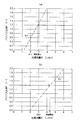
なお、図3では、缶体流量Qcが燃焼停止缶体流量Qcf及び燃焼開始缶体流量Qcnのときの出湯流量Qtとバイパス比率Pとの関係が一点鎖線及び二点鎖線でそれぞれ示されているので、同図において、斜線で示す領域がバーナーの燃焼停止領域、交斜線で示す領域がバーナーの燃焼開始領域となり、燃焼停止領域の外側から燃焼停止領域に進入した時点でバーナーの燃焼が停止され、燃焼開始領域の外側から燃焼開始領域に進入した時点でバーナーの燃焼が開始されることになる。また、この給湯システム1では、缶体流量Qcを流量センサ29によって実測しているだけなので、出湯流量Qtについては、実測された缶体流量Qc、熱交換器温度Tc、混合温水温度Tm及び低温水温度Twから、数1に示す演算式に従って算出している。
【0037】
【数1】

ところで、この給湯システム1では、上述したように、出湯中は、バーナーが燃焼状態であるか、非燃焼状態であるかに拘わらず、バイパス比率Pが概ね1.2程度になるように、バイパス弁24aの開度が保持されるようになっているので、図4(a)に示すように、出湯中に出湯流量Qtが徐々に低下してくると、出湯流量Qtが燃焼停止出湯流量Qtfを下回る前に、缶体流量Qcが燃焼停止缶体流量Qcfを下回ってしまい、出湯流量Qtが燃焼停止出湯流量Qtfを上回っているにも拘わらず、バーナーの燃焼が停止してしまうことになる。また、出湯を開始した後、出湯流量Qtが徐々に上昇する場合は、同図(b)に示すように、缶体流量Qcが燃焼開始缶体流量Qcnを上回る前に、出湯流量Qtが燃焼開始出湯流量Qtnを上回ってしまい、出湯流量Qtが燃焼開始出湯流量Qtnを上回っているにも拘わらず、バーナーの燃焼が開始されないといった問題が発生する。
【0039】
そこで、この給湯システム1では、バーナーが燃焼している状態において、缶体流量Qcが燃焼停止缶体流量Qcf付近まで近づくと、出湯流量Qtが燃焼停止出湯流量Qtfを下回る前に、缶体流量Qcが燃焼停止缶体流量Qcfを下回らないように、出湯流量Qtに応じてバイパス弁24aの最大開度(最大バイパス比率Pmax)を制限するようになっており、バーナーが燃焼していない状態において、出湯流量Qtが燃焼開始出湯流量Qtn付近まで近づくと、缶体流量Qcが燃焼開始缶体流量Qcn以上になる前に、出湯流量Qtが燃焼開始出湯流量Qtn以上にならないように、出湯流量Qtに応じてバイパス弁24aの最大開度(最大バイパス比率Pmax)を制限するようになっている。
【0040】
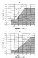
即ち、バーナーが燃焼している状態において、出湯流量Qtが低下してくる場合は、数2に示す演算式に従って、そのときの出湯流量Qtにおける最大バイパス比率Pmaxを算出し、その算出された最大バイパス比率Pmaxを上回らないように、バイパス弁24aの最大開度を制限するようになっており、バーナーが燃焼していない状態において、出湯流量Qtが上昇していく場合は、数3に示す演算式に従って、そのときの出湯流量Qtにおける最大バイパス比率Pmaxを算出し、その算出された最大バイパス比率Pmaxを上回らないように、バイパス弁24aの最大開度を制限するようになっている。なお、図5には、数2及び数3に示す演算式に従って算出された出湯流量Qtに対する最大バイパス比率Pmaxを実線及び破線でそれぞれ示している。
【0041】
【数2】
【数3】
従って、この給湯システム1では、バーナーが燃焼しながら出湯を行っている状態では、図6(a)に斜線で示す領域内において、出湯流量Qtが低下していくことになるので、出湯流量Qtが燃焼停止出湯流量Qtfを下回った後に、缶体流量Qcが燃焼停止缶体流量Qcfを下回ることになり、出湯流量Qtが燃焼停止出湯流量Qtfを下回った時点で確実にバーナーの燃焼が停止されることになる。
【0044】
また、バーナーが燃焼していない状態では、同図(b)に斜線で示す領域内において、出湯流量Qtが上昇していくことになるので、缶体流量Qcが燃焼開始缶体流量Qcnを上回った後に、出湯流量Qtが燃焼開始出湯流量Qtnを上回ることになり、出湯流量Qtが燃焼開始出湯流量Qtnを上回った時点で確実にバーナーの燃焼が開始されることになる。
【0045】
以上のように、この給湯システム1では、出湯流量Qtが小流量域に入ってくると、最大バイパス比率Pmaxが制限されることになるので、バイパス弁24aが出湯温度制御を確実に行うことができず、出湯温度が一時的に乱れることになるが、こういった小流量域で出湯を行うことはほとんどないので、特に、問題になることはない。
【0046】
なお、上述した実施形態では、出湯中に混合調節弁21が固定温度制御から給湯設定温度制御に切り換わると、混合調節弁21から送出される温水の温度(混合温水温度Tm)が給湯設定温度Te−1℃まで上昇した時点から、所定時間(例えば、5秒)が経過した時点で、バイパス弁24aを、バーナーの燃焼中に出湯温度制御を行っていたときの弁開度に相当する所定開度に保持するようになっているが、これに限定されるものではなく、混合温水温度Tmが給湯設定温度Te−1℃まで上昇した時点で、バイパス弁24aを所定開度に保持したり、混合温水温度Tmが給湯設定温度Teを中心とした所定の温度範囲(例えば、給湯設定温度Te±1℃)内で安定した時点で、バイパス弁24aを所定開度に保持することも可能である。
【0047】
また、上述した実施形態では、出湯中に混合調節弁21が固定温度制御から給湯設定温度制御に切り換わると、バイパス弁24aを、バーナーの燃焼中に出湯温度制御を行っていたときの弁開度に相当する、予め定められた所定開度(上述した実施形態の場合は、バイパス比率Pが1.2程度になるような弁開度)に保持するようになっているが、これに限定されるものではなく、バーナーの燃焼を停止する直前の弁開度を記憶しておき、その弁開度に保持することも可能である。
【0048】
また、上述した実施形態では、混合調節弁21が固定温度制御を行う場合の目標温度である固定温度Tfを、給湯設定温度Te−10℃に設定しているが、これに限定されるものではなく、例えば、給湯設定温度Teが60℃以上、60℃未満35℃以上、35℃未満に場合分けし、60℃以上の場合は45℃、60℃未満35℃以上の場合は30℃、35℃未満の場合は25℃といった具合に、給湯設定温度Teに応じて、固定温度Tfを段階的に設定することも可能である。ただし、その場合は、設定された固定温度Tfに応じて、バーナーの燃焼を停止したときに保持すべきバイパス比率Pを算出し、そのバイパス比率Pになるような弁開度にバイパス弁24aの開度を保持する必要がある。
【0049】
また、上述した実施形態では、混合調節弁21が組み込まれた給湯器20を使用した給湯システムについて説明したが、これに限定されるものではなく、混合調節弁を有する給湯接続ユニットを介して、太陽熱利用温水器と通常の給湯器とを接続した給湯システムについても、本発明を適用することができることはいうまでもない。
【0050】
また、上述した実施形態では、補助熱源が太陽熱である給湯システムについて説明したが、補助熱源はこういった太陽熱に限定されるものではなく、例えば、コージェネレーションシステムにおけるガスエンジンやガスタービンの排熱を補助熱源とした給湯システムのように、種々の補助熱源を使用した給湯システムについて、本発明を適用することができることはいうまでもない。
【図面の簡単な説明】
【図1】この発明にかかる給湯システムの一実施形態を示す概略構成図である。
【図2】同上の給湯システムにおいて、出湯中に混合調節弁が固定温度制御から給湯設定温度制御に切り換わった時点における運転状態を示す図である。
【図3】同上の給湯システムに使用されている給湯器におけるバーナーの燃焼停止タイミング及び燃焼開始タイミングを説明するための説明図である。
【図4】(a)、(b)はバーナーの燃焼停止時に保持するバイパス弁の開度を、バーナーの燃焼中におけるバイパス弁の開度に相当する所定開度に設定した場合の問題点を説明するための説明図である。
【図5】同上の問題点を解決するための手法を説明するための説明図である。
【図6】(a)は同上の手法を採用した場合のバーナーの燃焼停止タイミングを説明するための説明図、(b)は同上の手法を採用した場合のバーナーの燃焼開始タイミングを説明するための説明図である。
【符号の説明】
1 給湯システム
10 太陽熱利用温水器
14 蓄熱槽
15、17 給水管
16 予熱温水供給管
20 給湯器
20a コントローラ
21 混合調節弁
22 熱交換器
23 メイン流路
24 バイパス流路
24a バイパス弁
25 バイパス管
25a 電磁弁
26a 予熱温水温度センサ
26b 低温水温度センサ
27 混合温水温度センサ
28 熱交換器温度センサ
29 流量センサ
30 操作リモコン
30a コントローラ[0001]
BACKGROUND OF THE INVENTION
The present invention relates to a hot water supply system in which a hot water heater supplies hot water using preheated hot water generated by an auxiliary heat source such as solar heat.
[0002]
[Prior art]
As a hot water supply system using an auxiliary heat source, for example, a solar water heater having a heat storage tank for storing preheated hot water generated using solar heat as an auxiliary heat source and a hot water heater as a main heat source are combined. Conventional hot water supply systems are generally known.
[0003]
In such a hot water supply system, the heat storage tank of the solar water heater is connected to the water heater, and the preheated hot water stored in the heat storage tank of the solar water heater is sent to the water heater at the time of hot water. However, instead of sending the preheated hot water sent from the heat storage tank to the heat exchanger as it is, low-temperature water (water with a lower temperature than normal-temperature tap water or preheated hot water) as needed The mixing control valve for mixing the preheated hot water and low temperature water sent from the heat storage tank at an arbitrary mixing ratio is provided upstream of the heat exchanger so that it can be sent to the heat exchanger in a mixed state. A built-in water heater may be used.
[0004]
In addition, a bypass channel that bypasses the heat exchanger is usually connected to the main channel in the water heater that sends hot water from the mixing control valve to the heat exchanger. A bypass valve for generating hot water having a hot water supply set temperature by appropriately mixing hot water heated by the exchanger with hot water having a relatively low temperature delivered from the mixing control valve is installed.
[0005]
In a hot water supply system using a water heater with a built-in mixing control valve, when preheated hot water that is higher than the hot water set temperature set for the water heater is stored in the heat storage tank, the mixing control valve is Burner that heats the heat exchanger by generating hot water at a hot water supply set temperature by appropriately mixing preheated hot water that is higher than the hot water set temperature sent from the heat storage tank and low temperature water and sending it to the heat exchanger The hot water at the hot water supply set temperature is discharged without burning the water. On the other hand, when preheated hot water equal to or higher than the hot water supply set temperature is not stored in the heat storage tank, the mixing control valve is determined in advance by appropriately mixing preheated hot water lower than the hot water supply set temperature sent from the heat storage tank with low temperature water. When the temperature is lowered to the fixed temperature, the heat is sent to the heat exchanger, the burner is burned to heat the heat exchanger, and hot water is discharged while generating hot water at the hot water supply set temperature.
[0006]
Therefore, in such a hot water supply system, preheated hot water at or above the hot water supply set temperature is sent from the heat storage tank to the mixing control valve in a state where hot water at the hot water supply set temperature is discharged by burning the burner of the water heater. At that time, the mixing control valve starts to generate hot water at the hot water supply set temperature, and a burner combustion stop command is output to stop the combustion of the water heater burner. Since the temperature does not decrease immediately and the hot water at the hot water supply set temperature is not immediately sent to the heat exchanger, the bypass valve remains hot water at the hot water supply set temperature even after combustion of the burner stops. The hot water temperature control is continued so that the hot water is continuously discharged, and when the temperature of the heat exchanger falls below a predetermined temperature, the fixed opening degree is set in advance. .
[0007]
[Problems to be solved by the invention]
By the way, in the state where hot water of the hot water supply set temperature is discharged while burning the burner, the bypass ratio (the flow rate of hot water passing through the bypass channel / the flow rate of hot water passing through the heat exchanger) is usually about 1.2. As shown in the figure, the fixed temperature and the heat exchanger temperature are set, so the hot water temperature control is performed with the bypass valve being quite open, but after the water heater burner stops combustion, the temperature of the heat exchanger When the temperature falls below the preset predetermined temperature, the bypass ratio is set to be about 0.6, so in the state where hot water at the hot water supply set temperature is discharged without burning the burner, The bypass valve is kept fairly closed.
[0008]
For this reason, the hot water flow rate in a state where the burner stops combustion will be lower than the hot water flow rate in a state where the burner is burning, for example, when performing automatic hot water filling to the bathtub, The time required for automatic hot water filling differs between the day when the temperature of the preheated hot water stored in the heat storage tank is higher than the hot water supply set temperature (bath set temperature) and the day when it is below the hot water set temperature (bath set temperature). There is a problem. In addition, when the burner is switched from the combustion state to the non-combustion state during use of the shower, there is a problem in that a good feeling of use cannot be obtained because the shower flow rate fluctuates in the middle.
[0009]
Then, the subject of this invention is providing the hot water supply system which can ensure the hot water flow rate comparable as the case where the burner is burning, even when the burner is not burning.
[0010]
[Means for solving the problems and effects thereof]
In order to solve the above-mentioned problem, the invention according to
[0011]
As described above, in this hot water supply system, when the mixing control valve performs the hot water supply set temperature control, the bypass valve is Opening just before stopping heat exchanger heating or Since the heat exchanger is kept at a predetermined opening degree that corresponds to the opening degree during heating, the outlet water flow rate in a state where the burner stops combustion is in the state where the burner is burning. There is no drop compared to the hot water flow rate.
[0012]
In order to solve the above-mentioned problem, the invention according to
[0013]
As described above, in this hot water supply system, when the mixing control valve is switched from the fixed temperature control to the hot water supply set temperature control in the hot water, that is, when the burner of the hot water heater is switched from the combustion state to the non-combustion state, The bypass valve performs tapping temperature control until the temperature of the exchanger falls below a predetermined temperature, and when the temperature of the heat exchanger falls below a predetermined temperature, the bypass valve temporarily reaches a fixed opening. After being held, when the hot water near the hot water supply set temperature starts to be sent from the mixing control valve, it corresponds to the opening just before the bypass valve stops heating the heat exchanger or the opening during heating of the heat exchanger In order to minimize the fluctuations in the temperature of the hot water as the mixing control valve is controlled and the combustion state of the burner is switched during the hot water. One, it is possible to suppress the fluctuation of the hot water flow rate.
[0014]
More specifically, as in the hot water supply system according to the third aspect of the present invention, in the hot water, the hot water supplied from the mixing control valve after the mixing control valve has shifted from the fixed temperature control to the hot water supply set temperature control. However, when the temperature is raised to a predetermined temperature lower than the hot water supply set temperature, which is preset with respect to the hot water supply set temperature, the opening degree immediately before the heating of the heat exchanger is stopped or the heat exchanger What is necessary is just to make it hold | maintain at the predetermined opening degree preset corresponding to the opening degree during heating.
[0015]
After the mixing control valve shifts from the fixed temperature control to the hot water supply set temperature control, the temperature of the hot water sent from the mixing control valve is not necessarily stable and may converge to the hot water supply set temperature while hunting. Therefore, as in the hot water supply system of the invention according to
[0016]
Also, in order to prevent boiling of hot water in the heat exchanger, the flow rate of hot water passing through the heat exchanger is determined in advance when the burner that heats the heat exchanger is burning. In the case of a water heater in which the burner is configured to stop combustion when the temperature falls below or when the flow rate of hot water from the water heater falls below a predetermined combustion stop hot water flow rate, as described above, When the mixing control valve performs the hot water supply set temperature control, the bypass valve is set to a predetermined value corresponding to the opening degree immediately before stopping the heating of the heat exchanger or the opening degree during heating of the heat exchanger. If the opening is kept at the opening, the hot water flow rate passing through the heat exchanger will be lower than the combustion stop warm water flow rate before the hot water flow rate falls below the combustion stop hot water flow rate, and the hot water flow rate will exceed the combustion stop hot water flow rate. While Regardless, a new problem that combustion of the burner stops occurs, so that the heat exchanger passes through the heat exchanger in a state where the burner is burning as in the hot water supply system of the invention according to
[0017]
Also, in order to prevent boiling of hot water in the heat exchanger, the flow rate of hot water passing through the heat exchanger is determined in advance when the burner that heats the heat exchanger is not combusting. In the case of the hot water heater in which the burner starts to combust when the hot water flow rate from the water heater becomes equal to or higher than the predetermined combustion start hot water flow rate, the mixing adjustment is performed as described above. When the valve is performing hot water supply set temperature control, the bypass valve is set to a predetermined opening degree that corresponds to the opening degree immediately before stopping the heat exchanger heating or the opening degree during heating of the heat exchanger. If the hot water flow rate exceeds the combustion start hot water flow rate, the hot water flow rate passing through the heat exchanger will exceed the combustion start hot water flow rate, and the hot water flow rate will exceed the combustion start hot water flow rate. I am also Thus, a new problem that the burner does not start combustion occurs. Therefore, in the state where the burner is not combusting as in the hot water supply system of the invention according to
[0018]
DETAILED DESCRIPTION OF THE INVENTION
Hereinafter, embodiments will be described with reference to the drawings. FIG. 1 shows a schematic configuration of a hot
[0019]
The solar-
[0020]
In the solar collector 11, a heat medium circulation path is formed by a
[0021]
The
[0022]
In addition, a
[0023]
Further, the preheated hot
[0024]
Further, the
[0025]
The
[0026]
If the temperature of the preheated hot water delivered from the
[0027]
On the other hand, when the preheated hot water temperature Tp is lower than the hot water supply set temperature Te, the hot water at the hot water supply set temperature Te cannot be supplied unless the burner in the
[0028]
In this case, the burner of the
[0029]
Further, when the hot water is stopped, if the burner is burning, the combustion is stopped, and the
[0030]
In addition, since preheated hot water that is lower than the hot water supply set temperature Te is sent from the
[0031]
Further, when the mixing
[0032]
Thereafter, when the temperature of the hot water sent from the mixing control valve 21 (mixed hot water temperature Tm) rises to the hot water supply set temperature Te-1 ° C., the bypass is performed when a predetermined time (for example, 5 seconds) elapses from that point. The
[0033]
As described above, in the hot
[0034]
In particular, when the mixing
[0035]
Further, in the state where the burner is combusting, even if a certain amount of hot water flow rate Qt is secured, if for some reason the can body flow rate Qc is extremely low, the hot water passing through the
[0036]
In FIG. 3, the relationship between the tapping flow rate Qt and the bypass ratio P when the can body flow rate Qc is the combustion stop can body flow rate Qcf and the combustion start can body flow rate Qcn is shown by a one-dot chain line and a two-dot chain line, respectively. Therefore, in the figure, the hatched region is the burner combustion stop region, and the cross hatched region is the burner combustion start region, and the burner combustion is stopped when entering the combustion stop region from outside the combustion stop region. When the burner enters the combustion start region from outside the combustion start region, combustion of the burner is started. Moreover, in this hot
[0037]
[Expression 1]
By the way, in the hot
[0039]
Therefore, in this hot
[0040]
That is, when the hot water flow rate Qt decreases while the burner is burning, the maximum bypass ratio Pmax at the hot water flow rate Qt at that time is calculated according to the arithmetic expression shown in
[0041]
[Expression 2]
[Equation 3]
Therefore, in this hot
[0044]
Further, in the state where the burner is not combusting, the tapping flow rate Qt increases in the hatched region in FIG. 5B, so that the can body flow rate Qc exceeds the combustion start can body flow rate Qcn. After that, the hot water flow rate Qt exceeds the combustion start hot water flow rate Qtn, and combustion of the burner is surely started when the hot water flow rate Qt exceeds the combustion start hot water flow rate Qtn.
[0045]
As described above, in this hot
[0046]
In the above-described embodiment, when the mixing
[0047]
In the above-described embodiment, when the mixing
[0048]
Moreover, in embodiment mentioned above, although the fixed temperature Tf which is target temperature in case the mixing
[0049]
In the above-described embodiment, the hot water supply system using the
[0050]
In the above-described embodiment, the hot water supply system in which the auxiliary heat source is solar heat has been described. However, the auxiliary heat source is not limited to such solar heat, and for example, exhaust heat of a gas engine or a gas turbine in a cogeneration system. Needless to say, the present invention can be applied to a hot water supply system using various auxiliary heat sources, such as a hot water supply system using an auxiliary heat source.
[Brief description of the drawings]
FIG. 1 is a schematic configuration diagram showing an embodiment of a hot water supply system according to the present invention.
FIG. 2 is a diagram showing an operating state at the time when the mixing control valve is switched from fixed temperature control to hot water supply set temperature control during hot water discharge in the hot water supply system same as above.
FIG. 3 is an explanatory diagram for explaining a combustion stop timing and a combustion start timing of a burner in a water heater used in the above hot water supply system.
4 (a) and 4 (b) show problems when the opening degree of the bypass valve held when the burner is stopped is set to a predetermined opening degree corresponding to the opening degree of the bypass valve during combustion of the burner. It is explanatory drawing for demonstrating.
FIG. 5 is an explanatory diagram for explaining a technique for solving the same problem as above.
6A is an explanatory diagram for explaining the combustion stop timing of the burner when the above method is employed, and FIG. 6B is a diagram for explaining the combustion start timing of the burner when the above method is employed. It is explanatory drawing of.
[Explanation of symbols]
1 Hot water supply system
10 Solar water heater
14 Thermal storage tank
15, 17 Water supply pipe
16 Preheated hot water supply pipe
20 Water heater
20a controller
21 Mixing control valve
22 Heat exchanger
23 Main channel
24 Bypass channel
24a Bypass valve
25 Bypass pipe
25a solenoid valve
26a Preheating hot water temperature sensor
26b Low temperature water temperature sensor
27 Mixed hot water temperature sensor
28 Heat exchanger temperature sensor
29 Flow sensor
30 Operation remote control
30a controller
Claims (6)
前記給湯器は、前記混合調節弁から送出される温水を、前記熱交換器を通して送出するメイン流路と、前記メイン流路における前記熱交換器の前後に接続されたバイパス流路と、前記バイパス流路に設置されたバイパス弁とを備え、
前記混合調節弁に送出される前記予熱温水が給湯設定温度以上の場合は、前記熱交換器を加熱することなく、前記混合調節弁が給湯設定温度の温水を生成する給湯設定温度制御を行い、
前記混合調節弁に送出される前記予熱温水が給湯設定温度を下回る場合は、前記混合調節弁が、給湯設定温度より低い予め定められた固定温度の温水を生成する固定温度制御を行いながら、前記熱交換器を加熱することによって、給湯設定温度の温水を生成するようになっており、
出湯中において、前記熱交換器を加熱している間は、前記バイパス弁が、前記メイン流路から送出される温水の温度が給湯設定温度になるように弁開度を調整する出湯温度制御を行うようになっている給湯システムであって、
出湯中において、前記混合調節弁が給湯設定温度制御を行っているときは、前記バイパス弁を、前記熱交換器の加熱を停止する直前における開度または前記熱交換器の加熱中の開度に相当する、予め設定された所定開度に保持するようにしたことを特徴とする給湯システム。It is equipped with a mixing control valve that feeds the preheated hot water generated by the auxiliary heat source to the heat exchanger of the water heater while mixing low temperature water as necessary.
The water heater includes a main flow path for sending hot water sent from the mixing control valve through the heat exchanger, a bypass flow path connected before and after the heat exchanger in the main flow path, and the bypass A bypass valve installed in the flow path,
When the preheated hot water sent to the mixing control valve is equal to or higher than the hot water supply set temperature, the hot water supply set temperature control is performed so that the mixing control valve generates hot water at the hot water supply set temperature without heating the heat exchanger.
When the preheated hot water sent to the mixing control valve is lower than a hot water supply set temperature, the mixing control valve performs a fixed temperature control for generating hot water having a predetermined fixed temperature lower than the hot water supply set temperature, By heating the heat exchanger, hot water at the hot water supply set temperature is generated,
During heating, while the heat exchanger is being heated, the bypass valve controls the temperature of the hot water to adjust the valve opening so that the temperature of the hot water sent from the main flow path becomes the hot water supply set temperature. A hot water supply system designed to perform,
During hot water, when the mixing control valve is performing hot water supply set temperature control, the bypass valve is set to an opening just before stopping the heating of the heat exchanger or an opening during heating of the heat exchanger. A hot water supply system corresponding to a predetermined opening degree set in advance is provided.
前記給湯器は、前記混合調節弁から送出される温水を、前記熱交換器を通して送出するメイン流路と、前記メイン流路における前記熱交換器の前後に接続されたバイパス流路と、前記バイパス流路に設置されたバイパス弁とを備え、
前記混合調節弁に送出される前記予熱温水が給湯設定温度以上の場合は、前記熱交換器を加熱することなく、前記混合調節弁が給湯設定温度の温水を生成する給湯設定温度制御を行い、
前記混合調節弁に送出される前記予熱温水が給湯設定温度を下回る場合は、前記混合調節弁が、給湯設定温度より低い予め定められた固定温度の温水を生成する固定温度制御を行いながら、前記熱交換器を加熱することによって、給湯設定温度の温水を生成するようになっており、
出湯中において、前記熱交換器を加熱している間は、前記バイパス弁が、前記メイン流路から送出される温水の温度が給湯設定温度になるように弁開度を調整する出湯温度制御を行うようになっている給湯システムであって、
前記バイパス弁は、出湯中において、前記熱交換器の加熱を停止した後、前記熱交換器の温度が予め定められた所定温度を下回るまでの間は、前記メイン流路から送出される温水の温度が給湯設定温度になるように弁開度を調整する出湯温度制御を行い、前記熱交換器の温度が予め定められた所定温度を下回った時点で、予め定められた固定開度に保持されるようになっており、
出湯中において、前記混合調節弁が固定温度制御から給湯設定温度制御に移行した後、前記混合調節弁から給湯設定温度付近の温水が送出され始めた時点で、前記バイパス弁を、前記熱交換器の加熱を停止する直前における開度または前記熱交換器の加熱中の開度に相当する、予め設定された所定開度に保持するようにしたことを特徴とする給湯システム。It is equipped with a mixing control valve that feeds the preheated hot water generated by the auxiliary heat source to the heat exchanger of the water heater while mixing low temperature water as necessary.
The water heater includes a main flow path for sending hot water sent from the mixing control valve through the heat exchanger, a bypass flow path connected before and after the heat exchanger in the main flow path, and the bypass A bypass valve installed in the flow path,
When the preheated hot water sent to the mixing control valve is equal to or higher than the hot water supply set temperature, the hot water supply set temperature control is performed so that the mixing control valve generates hot water at the hot water supply set temperature without heating the heat exchanger.
When the preheated hot water sent to the mixing control valve is lower than a hot water supply set temperature, the mixing control valve performs a fixed temperature control for generating hot water having a predetermined fixed temperature lower than the hot water supply set temperature, By heating the heat exchanger, hot water at the hot water supply set temperature is generated,
During heating, while the heat exchanger is being heated, the bypass valve controls the temperature of the hot water to adjust the valve opening so that the temperature of the hot water sent from the main flow path becomes the hot water supply set temperature. A hot water supply system designed to perform,
In the hot water, the bypass valve stops the heating of the heat exchanger, and then waits until the temperature of the heat exchanger falls below a predetermined temperature. Hot water temperature control is performed to adjust the valve opening so that the temperature becomes the hot water supply set temperature, and when the temperature of the heat exchanger falls below a predetermined temperature, the temperature is maintained at a predetermined fixed opening. It is supposed to
In the hot water, after the mixing control valve shifts from fixed temperature control to hot water supply set temperature control, when the hot water near the hot water supply set temperature starts to be sent from the mixing control valve, the bypass valve is connected to the heat exchanger. The hot water supply system is characterized in that it is held at a predetermined opening degree that corresponds to the opening degree immediately before stopping the heating or the opening degree during heating of the heat exchanger.
前記バーナーが燃焼している状態において、前記熱交換器を通過する温水流量が燃焼停止温水流量付近まで近づくと、出湯流量が燃焼停止出湯流量を下回る前に、前記熱交換器を通過する温水流量が燃焼停止温水流量を下回らないように、前記バイパス弁の開度を調整するようにしたことを特徴とする請求項1、2、3または4に記載の給湯システム。In a state where the burner that heats the heat exchanger is burning, when the flow rate of hot water passing through the heat exchanger falls below a predetermined combustion stop warm water flow rate, or the flow rate of hot water from the water heater is The burner stops the combustion when it falls below the predetermined stoppage of hot water flow,
In the state where the burner is burning, when the flow rate of hot water passing through the heat exchanger approaches the vicinity of the combustion stop hot water flow rate, the flow rate of hot water passing through the heat exchanger before the hot water flow rate falls below the combustion stop hot water flow rate 5. The hot water supply system according to claim 1, wherein the opening degree of the bypass valve is adjusted so that the flow rate does not fall below the combustion stop hot water flow rate.
前記バーナーが燃焼していない状態において、出湯流量が燃焼開始出湯流量付近まで近づくと、前記熱交換器を通過する温水流量が燃焼開始温水流量以上になる前に、出湯流量が燃焼開始出湯流量以上にならないように、前記バイパス弁の開度を調整するようにした請求項1、2、3、4または5に記載の給湯システム。In a state where the burner for heating the heat exchanger is not combusted, the flow rate of hot water passing through the heat exchanger is equal to or higher than a predetermined combustion start hot water flow rate, and the flow rate of hot water from the water heater is predetermined. When the combustion start hot water flow rate is exceeded, the burner starts to burn,
In a state where the burner is not combusted, when the hot water flow rate approaches the vicinity of the combustion start hot water flow rate, the hot water flow rate that exceeds the combustion start hot water flow rate becomes greater than or equal to the combustion start hot water flow rate before the hot water flow rate that passes through the heat exchanger exceeds the combustion start hot water flow rate. The hot water supply system according to claim 1, 2, 3, 4 or 5, wherein the opening degree of the bypass valve is adjusted so as not to become.
Priority Applications (1)
| Application Number | Priority Date | Filing Date | Title |
|---|---|---|---|
| JP2002193692A JP3705246B2 (en) | 2002-07-02 | 2002-07-02 | Hot water system |
Applications Claiming Priority (1)
| Application Number | Priority Date | Filing Date | Title |
|---|---|---|---|
| JP2002193692A JP3705246B2 (en) | 2002-07-02 | 2002-07-02 | Hot water system |
Publications (2)
| Publication Number | Publication Date |
|---|---|
| JP2004036980A JP2004036980A (en) | 2004-02-05 |
| JP3705246B2 true JP3705246B2 (en) | 2005-10-12 |
Family
ID=31702599
Family Applications (1)
| Application Number | Title | Priority Date | Filing Date |
|---|---|---|---|
| JP2002193692A Expired - Fee Related JP3705246B2 (en) | 2002-07-02 | 2002-07-02 | Hot water system |
Country Status (1)
| Country | Link |
|---|---|
| JP (1) | JP3705246B2 (en) |
Families Citing this family (7)
| Publication number | Priority date | Publication date | Assignee | Title |
|---|---|---|---|---|
| ES1062435Y (en) * | 2006-03-09 | 2006-12-01 | Aguilera Francisco Jo Gonzalez | ELECTROMECHANICAL SWITCH FOR THE AUXILIARY HEATER IN THERMAL SOLAR SYSTEMS |
| JP4786504B2 (en) | 2006-11-10 | 2011-10-05 | 川崎重工業株式会社 | Heat medium supply facility, solar combined power generation facility, and control method thereof |
| JP5175138B2 (en) * | 2008-05-30 | 2013-04-03 | リンナイ株式会社 | Water heater |
| JP5295985B2 (en) * | 2010-01-28 | 2013-09-18 | リンナイ株式会社 | Hot water system |
| JP2013036693A (en) * | 2011-08-09 | 2013-02-21 | Tokyo Gas Co Ltd | Supply water preheating system |
| CN102644965A (en) * | 2012-05-18 | 2012-08-22 | 苏州市时代工程咨询设计管理有限公司 | Joint water supply system integrating solar water heater and domestic gas water heater |
| KR101664792B1 (en) * | 2015-05-08 | 2016-10-12 | 주식회사 경동나비엔 | Apparatus for supplying hot water connected with solar energy and fuel burning equipment |
-
2002
- 2002-07-02 JP JP2002193692A patent/JP3705246B2/en not_active Expired - Fee Related
Also Published As
| Publication number | Publication date |
|---|---|
| JP2004036980A (en) | 2004-02-05 |
Similar Documents
| Publication | Publication Date | Title |
|---|---|---|
| JP3705246B2 (en) | Hot water system | |
| JP4718323B2 (en) | Water heater and operation method thereof | |
| JP2007132576A (en) | Connection type water heater | |
| JP4036141B2 (en) | Hot water system | |
| JP2010281531A (en) | Storage type hot water supply system and cogeneration system | |
| JP3962640B2 (en) | Water heater | |
| JP3699402B2 (en) | Hot water mixing unit | |
| JP4682490B2 (en) | Hot water system | |
| JP3726761B2 (en) | Hot water system | |
| JPH09184659A (en) | Hot water supply apparatus | |
| JP3864116B2 (en) | Hot water system | |
| JP3705245B2 (en) | Hot water system | |
| JP3714209B2 (en) | Hot water system | |
| JP3705247B2 (en) | Hot water system | |
| JP3714206B2 (en) | Hot water system | |
| JP3687616B2 (en) | Hot water system | |
| JP3720745B2 (en) | Water heater | |
| JP3876196B2 (en) | Hot water system | |
| JP2005147579A (en) | Gas combustion room heater and water heater | |
| JP3551496B2 (en) | Hot water storage system | |
| JP3740089B2 (en) | Hot water mixing unit | |
| JPH06347095A (en) | Hot water feeder | |
| JP2002277056A (en) | Hot-water supplying system | |
| JP3551498B2 (en) | Hot water storage system | |
| JP3730901B2 (en) | Water heater |
Legal Events
| Date | Code | Title | Description |
|---|---|---|---|
| A621 | Written request for application examination |
Free format text: JAPANESE INTERMEDIATE CODE: A621 Effective date: 20040521 |
|
| A977 | Report on retrieval |
Free format text: JAPANESE INTERMEDIATE CODE: A971007 Effective date: 20050418 |
|
| A131 | Notification of reasons for refusal |
Free format text: JAPANESE INTERMEDIATE CODE: A131 Effective date: 20050426 |
|
| A521 | Request for written amendment filed |
Free format text: JAPANESE INTERMEDIATE CODE: A523 Effective date: 20050607 |
|
| TRDD | Decision of grant or rejection written | ||
| A01 | Written decision to grant a patent or to grant a registration (utility model) |
Free format text: JAPANESE INTERMEDIATE CODE: A01 Effective date: 20050705 |
|
| A61 | First payment of annual fees (during grant procedure) |
Free format text: JAPANESE INTERMEDIATE CODE: A61 Effective date: 20050718 |
|
| R150 | Certificate of patent or registration of utility model |
Free format text: JAPANESE INTERMEDIATE CODE: R150 |
|
| FPAY | Renewal fee payment (event date is renewal date of database) |
Free format text: PAYMENT UNTIL: 20090805 Year of fee payment: 4 |
|
| FPAY | Renewal fee payment (event date is renewal date of database) |
Free format text: PAYMENT UNTIL: 20090805 Year of fee payment: 4 |
|
| FPAY | Renewal fee payment (event date is renewal date of database) |
Free format text: PAYMENT UNTIL: 20100805 Year of fee payment: 5 |
|
| FPAY | Renewal fee payment (event date is renewal date of database) |
Free format text: PAYMENT UNTIL: 20100805 Year of fee payment: 5 |
|
| FPAY | Renewal fee payment (event date is renewal date of database) |
Free format text: PAYMENT UNTIL: 20110805 Year of fee payment: 6 |
|
| FPAY | Renewal fee payment (event date is renewal date of database) |
Free format text: PAYMENT UNTIL: 20110805 Year of fee payment: 6 |
|
| FPAY | Renewal fee payment (event date is renewal date of database) |
Free format text: PAYMENT UNTIL: 20110805 Year of fee payment: 6 |
|
| FPAY | Renewal fee payment (event date is renewal date of database) |
Free format text: PAYMENT UNTIL: 20110805 Year of fee payment: 6 |
|
| FPAY | Renewal fee payment (event date is renewal date of database) |
Free format text: PAYMENT UNTIL: 20110805 Year of fee payment: 6 |
|
| FPAY | Renewal fee payment (event date is renewal date of database) |
Free format text: PAYMENT UNTIL: 20120805 Year of fee payment: 7 |
|
| FPAY | Renewal fee payment (event date is renewal date of database) |
Free format text: PAYMENT UNTIL: 20130805 Year of fee payment: 8 |
|
| R250 | Receipt of annual fees |
Free format text: JAPANESE INTERMEDIATE CODE: R250 |
|
| R250 | Receipt of annual fees |
Free format text: JAPANESE INTERMEDIATE CODE: R250 |
|
| R250 | Receipt of annual fees |
Free format text: JAPANESE INTERMEDIATE CODE: R250 |
|
| LAPS | Cancellation because of no payment of annual fees |