JP3703638B2 - Construction method of multi-strip pipes for underground cables such as electric power - Google Patents
Construction method of multi-strip pipes for underground cables such as electric power Download PDFInfo
- Publication number
- JP3703638B2 JP3703638B2 JP28883998A JP28883998A JP3703638B2 JP 3703638 B2 JP3703638 B2 JP 3703638B2 JP 28883998 A JP28883998 A JP 28883998A JP 28883998 A JP28883998 A JP 28883998A JP 3703638 B2 JP3703638 B2 JP 3703638B2
- Authority
- JP
- Japan
- Prior art keywords
- pipe
- propulsion
- cable
- propelling
- tube
- Prior art date
- Legal status (The legal status is an assumption and is not a legal conclusion. Google has not performed a legal analysis and makes no representation as to the accuracy of the status listed.)
- Expired - Fee Related
Links
Images


Description
【0001】
【発明の属する技術分野】
本発明は、電力等地中線ケーブルを多条敷設するための多条管の施工方法に関する。
【0002】
【従来の技術】
多条の地中ケーブルを敷設する従来の方法としては、推進管を用いる方法と、複数のケーブル格納管を用いる方法とがある。推進管を用いる方法は、大径の推進管を継ぎ足しながら推進し、この推進の後、ケーブルを格納するためのケーブル管を推進管内に配管するものである。ケーブル格納管を用いる方法は、小径のケーブル格納管を削進機によって個々に推進するものである。以下、図面を参照してそれぞれの方法について説明する。
【0003】
図8〜図12は推進管を用いる従来の方法を示す。まず、図8に示すように、地山に形成した一方の立坑100内に圧入装置120を設置し、圧入装置120によってシールド機130を他方の立坑110に向かって推進する。そして、図9に示すように、シールド機130の後に推進管140を順次、継ぎ足しながら他方の立坑110まで推進させる。推進管140は内部が空洞の管体であり、この推進管140の継ぎ足しによってシールド機130を送り出し、シールド機130が他方の立坑110に達した時点で、図10に示すようにシールド機130を立坑110から引き上げて撤去すると共に、圧入装置120を立坑100から撤去して推進を終了する。
【0004】
その後、図11で示すように、連続している推進管140の内部に必要条数のケーブル管150を挿入する。ケーブル管150はガラス繊維によって強度が付与された薄肉の管体であり、このケーブル管150の挿入の後、推進管140の内部に中詰めモルタルを圧送によって注入して充填し、図12で示すように施工を終了する。図12において、符号160は複数のケーブル管150及び中詰めモルタルによって内部が中実となった多条管である。
【0005】
図13及びそのX−X断面図である図14は多条管160の内部を示し、ケーブル管150が配管された推進管140の内部に、中詰めモルタル170が充填されることによって、ケーブル管150が相互に固定された状態となっている。
【0006】
図15〜図17は、ケーブル格納管180を用いる従来の方法であり、立坑100に削進機190を設置し、この削進機190によって一条のケーブル格納管180を推進する(図15)。その後、削進機190の高さを変更して次のケーブル格納管180を前段のケーブル格納管180と平行に推進する(図16)。この推進を繰り返して必要条数のケーブル格納管180を施工した後、掘進機190を撤去して終了する(図17)。
【0007】
【発明が解決しようとする課題】
しかしながら、推進管140を用いる従来の方法は、以下の問題点を有している。
(1)推進管140内にTPFPケーブル管150を配管するためには、推進管140内に作業者が入る必要があり、配管条数にかかわらず人間が管内作業できる呼び径800mm以上の推進管で施工しなければならず、内部での配管作業が可能な寸法とする必要がある。このため、推進管断面縮小には限界があり、重量が大きいばかりでなく、推進のためには大動力を要している。
(2)二工程式推進工法の場合、一工程目に使用する誘導管が必要となり、製作費用がかかるとともに、再使用にあたり、保管場所、メンテナンスに関する費用がかかる。
【0008】
次に、ケーブル格納管180を用いる従来の方法には、以下の問題点がある。
(1)削進口径が小さく、又、削進機190の推力が小さいため、石や不均一の硬度の地盤に遭遇した場合には、推進方向が狂ったり、蛇行するばかりでなく、方向修正が困難となっている。
(2)先行して推進したケーブル格納管180に、後から削進するケーブル格納管180が接触したり、当接して削進が不可能となる。
(3)削進力が弱いため、推進できる長さが短く、立坑を多く必要とする。このため、立坑を施工する工数が多くなっている。
【0009】
このようなことから本発明は、原則としては推進管を用いる工法とし、さらに推進管工法の問題点を解決することが可能な多条管の施工方法を提供することを目的とする。
【0010】
【課題を解決するための手段】
上記目的を達成するため、請求項1の発明の多条管の施工方法は、
掘進機を先頭にして推進管を順次、継ぎ足しながら推進始点から推進終点まで推進させる工程の後、ケーブル配線用の多条管を前記推進始点から前記推進終点まで順次継ぎ足しながら推進させる工程を行う二工程式の電力等地中線多条ケーブルの施工方法において、前記推進管の推進時に該推進管を押し出すための滑材を補助的に注入する工程と、二工程目の最初に使用する第一管の内部に予め裏込注入管,必要条数のケーブル格納管を格納管固定格子金具と共に配管する工程と、前記第一管を推進することで到達立坑に到達した掘進機を回収する工程と、前記第一管に設置済の裏込注入管と第二管の裏込注入管との接続確認後、第二管を推進する工程と、第二管を所定の長さまで推進した後、格納管配管用ガイドを利用し、第二管に設置する必要条数のケーブル格納管を第一管のケーブル格納管とそれぞれ接続する工程と、到達立坑で回収した前記推進管に、発進立坑部で裏込注入管、格納管固定格子金具を設置し、第二管に続けてこれを推進し、かつ前記ケーブル格納管の接続を行う工程を第一管が所定の位置に到達するまで、繰り返す工程と、二工程目の管の推進終了後の導通試験終了後、第一管および最終管口を閉塞し、中詰めモルタルを打設する工程と、を備えていることを特徴とする。
【0012】
【発明の実施の形態】
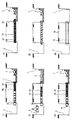
以下、図面を参照して本発明を具体的に説明すると、図1(1)〜(6)及び図2(1)〜(6)は本発明の多条管の施工方法の一実施形態を工程順に示すものである。
【0013】
図1(1)に示すように、推進開始側となる第1の立坑1及び推進終点となる第2の立坑2を地山に掘削し、第1の立坑1内に圧入装置3を配置する。そして、圧入装置3に羽口または掘進機4を連結し、圧入装置3の動力によって掘進機4を第2の立坑2に向かって推進する。
【0014】
掘進機4は掘進によって発生した泥を地山を掘進しながら排出するものであり、泥水式、泥土圧式、その他の公知の掘進機を使用することができる。図3は泥水式の掘進機4を示す。この羽口または掘進機4は管状のスキンプレート40の先端に、回転駆動されるカッターヘッド41が取り付けられて構成されている。カッターヘッド41には地山を掘削する複数のビット42が取り付けられており、カッターヘッド41の後側は、隔壁43によって後部と仕切られた圧力チャンバー44となっている。圧力チャンバー44には、泥水を圧送する送泥管45及び泥水を排出する排泥管46の先端部分が挿入されている。この構造のシールド機4は、密閉された圧力チャンバー44内に泥水を充満させることによって切羽の安定を行うと共に、カッターヘッドが掘削した土砂を泥水と混合して排出するようになっている。
【0015】
このような掘進機4の後側には、図1(2)に示すように推進管5を連結し、さらにその後側に次の推進管5を順次、連結しながら推進し一工程を継続する。この場合、推進管5を押し出すための滑材を補助的に注入しながら推進管5の推進を行う。推進管5としては従来の工法に使用された推進管と同様の構造のものを使用することができる。推進管5は、内部が中空の管体となっており、送泥管45、排泥管46の挿通が可能となっている。
【0016】
図1(3)は推進管5を継ぎ足しながら推進を行うことによって掘進機4が第2の立坑2に到達した工程を示す。この状態では、図示のように二工程目の最初に使用する第一管50の推進の準備がなされる。すなわち、中空管の内部に予め裏込注入管68,必要条数のケーブル格納管61を格納管固定格子金具72と共に配管する作業が行われる(図6に示された状態)。
【0017】
そして、図1(4)の工程で示したように、第一管50を圧入装置3により押し入れ、掘進機4を第2の立坑2から撤去して回収する。なお、土質、推進の進行によっては、中押しジャッキを備えた中押し装置(特願平8−143634号)を推進管5の間に挿入して推進力を増強させても良い。
【0018】
掘進機4を撤去した後、上記第一管50に続く後続の第二管51は、コンクリート管71等に、発進立坑1で裏込注入管68,格納管固定格子金具72を設置し、この第二管51を推進架台73に設置し、上記第一管50に設置済の裏込注入管68との接続確認後、第二管51を推進し、第二管51を所定の長さまで推進した(図1(6))後、図18に示した格納管配管用ガイド74を利用し、第一管50の格納管と第二管51の格納管とを必要条数接続し(図2(1))、更に到達立坑2で回収した次の推進管5、すなわち中空の管体であるコンクリート管71に、発進立坑1で裏込注入管68,格納管固定格子金具72を設置し、第一管50が所定の位置に到達するまで、前記第二管51の諸工程(図1(6)〜図2(3))を最終管52まで繰り返し(図2(4))、推進終了後の導通試験終了後、第一管50および最終管52の口を閉塞し、中詰めモルタルを打設する(図2(5))。
【0019】
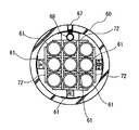
図4及び図5に示されているように、上述のケーブル格納管である内管61は、その内部にケーブルを配線するためのものであり、推進管5等に用いられるコンクリート管である外管60の内部に必要本数が挿入される。図示する形態では、内管61は3列3段に配管されている。
【0020】
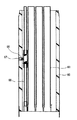
さらに、外管60の適宜部位には、外部と連通する裏込め注入孔67が形成されると共に、外管60の内部には裏込め注入管68が長さ方向に沿って挿入されて配管されている。なお、図6は、外管60に裏込注入管68、ケーブル格納管61及びこのケーブル格納管61を格納するための格納管固定格子金具72が設置された状態が示されている。
【0021】
図7は裏込め注入孔67及び裏込め注入管68の関係を示し、裏込め注入管68には、外管60の外側に向かう枝管68aが形成され、この枝管68aと裏込め注入孔67とがノズル管69によって連結されている。ノズル管69はその内部に逆止弁70を備えている。逆止弁70は裏込め注入管68側からの流れの通過が可能であるが、外側から裏込め注入管68に向かう流れを遮断するようになっている。このような裏込め注入孔67及び裏込め注入管68は、後述する裏込め注入材の吐出のために使用されるものである。
【0022】
以上の構造の多条管は、図1(4)に示すように、先行している推進管5と置き換えられる。多条管(50など)はケーブルを配線するための内管61を内部に一体的に有しており、多条管の連結と同時に、ケーブル管150(図12参照)が配管されたと同様の状態となる。従って、従来のように推進管140(図10等参照)の内部に、ケーブル管150を後から配管する必要がなくなる。このため、この実施の形態では、推進管5の外径及び多条管6の外径を小さくすることができる。
【0023】
例えば、直径150mmの内管61(ケーブル管150)を3列3段に配管する場合、従来の推進管140では、1.131m2の断面積となるが、この実施の形態の推進管5及び多条管6では、0.724m2の断面積で良く、35%以上の縮径を行うことができる。従って、推進断面が縮小され、小さな推力での推進ができ、装置全体の小型化ができるばかりでなく、排土量も少なくなり、施工を迅速に、且つ安価に行うことができる。
【0024】
以上のようにして多条管(50等)への置き換えの後、多条管と地盤との間の隙間に裏込め注入材を注入する。この裏込め注入は、裏込め注入管68に裏込め注入材(図示省略)を圧送して逆止弁70から裏込め注入材を吐出することによって行われる。この吐出によって裏込め注入材は、多条管と地山75との隙間76に充填される(図7及び図2(6)参照乞)。
【0025】
そして、裏込め注入材の充填によって多条管6と地山75とが密着するため、地山75の緩みを防止することができる。かかる裏込め注入においても、多条管の内部に裏込め注入管68が配管されているため、その作業を効率的に行うことができる。なお、裏込め注入材は、セメント、粘土、ベントナイト、その他の材料が水に分散したものであり、地山の土質によって配合成分が適宜変更されるものである。
【0026】
図19及び図20は、本発明の第二管の配管ガイド図及び状況を説明した図面である。なお、格納管配管用ガイド74は、図示の様に、棒状体の先端に拡径部を備えた構成を有している。
(1)先ず、第一管50に第二管51の中心線を合わせ、ジャッキなどにて推進し、接続する。この時に、裏込め注入管の接続を確認する(図19(1))。
(2)次いで、第一管50の格納管61に格納管用配管ガイド74(図18参照)の先端を挿入する(図19(2))。
(3)第二管51に格納管61を押し込む(図19(3))。
(4)格納管配管ガイド74により、徐々に中心線に合わせる(合ってくる)(図20(1))。
(5)格納管61の先端を第一管50内に押し込み、その後格納管用配管ガイド74を引き抜きハンマー等で所定の位置までたたき入れる(図20(2))。
(6)次の格納管61に格納管用配管ガイド74を移動する(図20(3))。
【0027】
【発明の効果】
又、多条管はケーブルの配線が可能な内管を備えているため、後からケーブル管を配管する必要がなく、多条管及び推進管を小径とすることができる。このため、推進が容易となると共に、迅速に施工することができる。さらに、ケーブル管の面倒な管内配管作業が不要となるため、作業性が向上する。
【0028】
加えて、本発明は従来の推進管を使用した工法であり、細径のケーブル格納管を削進する必要がないため、ケーブル格納管のように蛇行したり、削進が不可能となる心配がなくなる。
【0029】
本発明の仮管推進時(一工程目)には、土質状況、周辺環境に応じて施工実績の多い推進工法を選択できる。このため、施工の安全性、品質等問題なく確実な施工が可能となる。
【0030】
本工法は二工程式推進工法を採用しているが、一工程目に使用する仮管(コンクリート管)(符号5,符号71)を到達立坑にて回収し二工程目に再使用するため、二工程式推進工法で通常使用する誘導管を別途用意することを必要としない。
【0031】
本工法は同一条数を施工する場合、従来の工法と比較して推進断面を縮小できるため、推進設備の小型化、残土処理量の低減などコストを削減できる。たとえばφ150の格納管を9条(3条3段)施工する場合、従来の施工ではコンクリート管(呼び径1,000mm)で施工していたが、本工法ではコンクリート管(呼び径800mm)で施工可能なため、断面積は35%の削減となる。
【0032】
本工法は原則的に管内作業がなくなるので、従来の推進管呼び径800mm未満の施工も同様にできる。このため、必要条数に応じた推進径で施工するため、断面の縮小ができ、コスト削減となる。
【0033】
本工法は裏込め注入が可能なため、周辺地盤への影響が少ない。
【図面の簡単な説明】
【図1】(1)〜(6)は、本発明の一実施形態の施工工程図(前工程)である。
【図2】(1)〜(6)は、本発明の一実施形態の施工工程図(後工程)である。
【図3】 羽口または掘進機の断面図である。
【図4】 多条管の断面図である。
【図5】 多条管の断面図である。
【図6】 多条管の断面図である。
【図7】 裏込め注入を行う部分の断面図である。
【図8】 推進管を用いる従来の方法の施工前の断面図である。
【図9】 従来の方法における推進管の推進工程を示す断面図である。
【図10】 従来の方法におけるシールド機の回収工程の断面図である。
【図11】 従来の方法におけるケーブル管の配管を示す断面図である。
【図12】 従来の方法によって施工する終了段階の断面図である。
【図13】 従来の方法によって施工された推進管の断面図である。
【図14】 図15のX−X線断面図である。
【図15】 ケーブル格納管を用いる従来の方法の施工時の断面図である。
【図16】 複数のケーブル格納管を施工する工程の断面図である。
【図17】 複数のケーブル格納管の施工後の断面図である。
【図18】 本発明第二管配管ガイド図である。
【図19】 本発明第二管配管状況図(前工程)である。
【図20】 本発明第二管配管状況図(後工程)である。
【符号の説明】
1 第1の立坑
2 第2の立坑
3 圧入装置
4 掘進機
5 推進管
50 第一管
51 第二管
60 外管
61 内管
67 裏込め注入孔
68 裏込め注入管
69 ノズル管
70 逆止弁
71 コンクリート管
72 格納管固定格子金具
73 推進架台
74 格納管配管用ガイド[0001]
BACKGROUND OF THE INVENTION
The present invention relates to a method for constructing a multi-strip pipe for laying a multi-strip underground cable such as a power line.
[0002]
[Prior art]
As a conventional method of laying a multi-strand underground cable, there are a method using a propulsion pipe and a method using a plurality of cable storage pipes. In the method using a propulsion pipe, propulsion is performed while a large-diameter propulsion pipe is added, and after the propulsion, a cable pipe for storing a cable is provided in the propulsion pipe. In the method using a cable storage tube, a small-diameter cable storage tube is individually propelled by a cutting machine. Hereinafter, each method will be described with reference to the drawings.
[0003]
8 to 1 2 illustrates a conventional method of using the propulsion tube. First, as shown in FIG. 8 , a press-
[0004]
Thereafter, as shown in Figure 1 1, to insert the
[0005]
1 3 and 1 4 is its sectional view taken along line X-X represents the inside of the
[0006]
1. 5 to FIG. 1 7 is a conventional method of using a
[0007]
[Problems to be solved by the invention]
However, the conventional method using the
(1) In order to pipe the
(2) In the case of the two-step type propulsion method, a guide pipe used in the first step is required, which requires production costs and costs for storage space and maintenance for reuse.
[0008]
Next, the conventional method using the
(1) Since the cutting diameter is small and the thrust of the
(2) The
(3) Since the cutting force is weak, the length that can be propelled is short and many shafts are required. For this reason, the man-hour which constructs a shaft has increased.
[0009]
In view of the above, an object of the present invention is to provide a construction method using a propulsion pipe in principle and a construction method for a multi-strip pipe capable of solving the problems of the propulsion pipe construction method.
[0010]
[Means for Solving the Problems]
In order to achieve the above object, the method of constructing the multi-strip pipe of the invention of
After the step of propelling the propulsion pipe from the propulsion start point to the propulsion end point while sequentially adding the propulsion pipe with the excavator at the top, the step of propelling the multi-pipe for cable wiring from the propulsion start point to the propulsion end point is sequentially performed. In the construction method of a process type underground cable with multiple underground lines, a step of supplementarily injecting a lubricant for pushing out the propelling pipe at the time of propulsion of the propelling pipe, and a first used at the beginning of the second process recovering internal beforehand Urakomi injection tube of the tube, the steps of the pipe with storage tube fixed grating fitting the cable storage tube of required number of threads, a shield machine which has reached the arrival pit by promoting the pre Symbol first tube And after confirming the connection between the back injection pipe already installed in the first pipe and the back injection pipe of the second pipe, after propelling the second pipe, and after propelling the second pipe to a predetermined length, Install it in the second pipe using the containment pipe guide. The step of connecting the necessary number of cable storage pipes with the cable storage pipe of the first pipe respectively, and the propulsion pipe collected at the arrival vertical shaft, installing a back-injection pipe and a storage pipe fixing grid bracket at the start vertical shaft, Repeating the second pipe and propelling it, and repeating the process of connecting the cable storage pipe until the first pipe reaches a predetermined position, and the continuity test after the completion of the second pipe promotion After completion, the first pipe and the final pipe port are closed, and a step of placing a filling mortar is provided.
[0012]
DETAILED DESCRIPTION OF THE INVENTION
Hereinafter, the present invention will be specifically described with reference to the drawings. FIGS. 1 (1) to ( 6 ) and FIGS. 2 (1) to (6) show an embodiment of the method for constructing a multi-strip pipe according to the present invention. It shows in order of process.
[0013]
As shown in FIG. 1 (1) , a
[0014]
The
[0015]
A
[0016]
FIG. 1 (3) shows a process in which the
[0017]
And as shown in the process of FIG. 1 (4) , the 1st pipe |
[0018]
After removing the
[0019]
As shown in FIGS. 4 and 5 , the
[0020]
Further, a
[0021]
FIG. 7 shows the relationship between the
[0022]
As shown in FIG. 1 (4), the multi- tube having the above structure is replaced with the
[0023]
For example, when the inner pipe 61 (cable pipe 150) having a diameter of 150 mm is piped in three rows and three stages, the
[0024]
As described above, after the replacement with the multi-tube (such as 50) , the backfilling injection material is injected into the gap between the multi-tube and the ground. The back-filling injection is performed by ejecting back-filling injection material back-filling grout into the back-filling injection tube 68 (not shown) from the pumping to the
[0025]
And since the multi-strip |
[0026]
19 and 20 are drawings for explaining a pipe guide diagram and situation of the second pipe of the present invention. In addition, the storage
(1) First, the center line of the
(2) Next, the tip of the storage pipe piping guide 74 (see FIG. 18) is inserted into the
(3) The
(4) By the
(5) Push the distal end of the
(6) The storage
[0027]
【The invention's effect】
In addition, since the multi-strip pipe includes an inner pipe capable of wiring the cable, it is not necessary to pipe the cable pipe later, and the multi-strip pipe and the propulsion pipe can be reduced in diameter. Therefore, the propulsion is facilitated and the construction can be performed quickly. Furthermore, since troublesome in-pipe piping work for the cable pipe is not required, workability is improved.
[0028]
In addition, the present invention is a construction method using a conventional propulsion pipe, and since there is no need to cut a small-diameter cable storage pipe, there is a concern that it will meander like a cable storage pipe or that it cannot be cut. Disappears.
[0029]
At the time of propulsion of the temporary pipe of the present invention (first step), a propulsion method with a lot of construction results can be selected according to the soil condition and the surrounding environment. For this reason, reliable construction is possible without problems such as construction safety and quality.
[0030]
This method employs a two-stage propulsion method, but the temporary pipe (concrete pipe) (
[0031]
In the case of constructing the same number of strips, this construction method can reduce the propulsion cross section compared to the conventional construction method, and therefore can reduce costs such as downsizing the propulsion equipment and reducing the amount of residual soil treatment. For example, when constructing 9 pipes (3 sections, 3 stages) with a diameter of 150 mm, it was constructed with a concrete pipe (nominal diameter of 1,000 mm) in the conventional construction, but with this method, it was constructed with a concrete pipe (nominal diameter of 800 mm). Since this is possible, the cross-sectional area is reduced by 35%.
[0032]
In principle, the construction method eliminates the work in the pipe, so that the conventional construction with a nominal diameter of the propulsion pipe of less than 800 mm can be similarly performed. For this reason, since it constructs with the propulsion diameter according to the number of required stripes, a cross section can be reduced and it becomes cost reduction.
[0033]
Since this method can be backfilled, there is little impact on the surrounding ground.
[Brief description of the drawings]
FIGS. 1 (1) to (6) are construction process diagrams (pre-process) according to an embodiment of the present invention.
FIGS. 2 (1) to (6) are construction process diagrams (post-process) according to an embodiment of the present invention.
FIG. 3 is a cross-sectional view of a tuyere or excavator.
FIG. 4 is a cross-sectional view of a multi-tubular tube.
FIG. 5 is a cross-sectional view of a multi-tubular tube.
FIG. 6 is a cross-sectional view of a multi-tube.
FIG. 7 is a cross-sectional view of a portion where backfill injection is performed.
FIG. 8 is a sectional view before construction of a conventional method using a propulsion pipe.
FIG. 9 is a cross-sectional view showing a propulsion process of a propulsion pipe in a conventional method.
FIG. 10 is a cross-sectional view of a shield machine recovery step in a conventional method.
FIG. 11 is a cross-sectional view showing cable pipe piping in a conventional method.
FIG. 12 is a sectional view at the end stage of construction by a conventional method.
FIG. 13 is a cross-sectional view of a propulsion pipe constructed by a conventional method.
14 is a cross-sectional view taken along line XX of FIG.
FIG. 15 is a cross-sectional view of a conventional method using a cable storage tube during construction.
FIG. 16 is a cross-sectional view of a process for constructing a plurality of cable storage tubes.
FIG. 17 is a cross-sectional view after construction of a plurality of cable storage pipes.
FIG. 18 is a second pipe piping guide diagram of the present invention.
FIG. 19 is a second pipe piping situation diagram (pre-process) of the present invention.
FIG. 20 is a second pipe piping situation diagram (post-process) of the present invention.
[Explanation of symbols]
DESCRIPTION OF
Claims (1)
前記推進管の推進時に該推進管を押し出すための滑材を補助的に注入する工程と、
二工程目の最初に使用する第一管の内部に予め裏込注入管,必要条数のケーブル格納管を格納管固定格子金具と共に配管する工程と、
前記第一管を推進することで到達立坑に到達した掘進機を回収する工程と、
前記第一管に設置済の裏込注入管と第二管の裏込注入管との接続確認後、第二管を推進する工程と、
第二管を所定の長さまで推進した後、格納管配管用ガイドを利用し、第二管に設置する必要条数のケーブル格納管を第一管のケーブル格納管とそれぞれ接続する工程と、
到達立坑で回収した前記推進管に、発進立坑部で裏込注入管、格納管固定格子金具を設置し、第二管に続けてこれを推進し、かつ前記ケーブル格納管の接続を行う工程を第一管が所定の位置に到達するまで、繰り返す工程と、
二工程目の管の推進終了後の導通試験終了後、第一管および最終管口を閉塞し、中詰めモルタルを打設する工程と、
を備えていることを特徴とする電力等地中線ケーブルの多条管の施工方法。After the step of propelling the propulsion pipe from the propulsion start point to the propulsion end point while sequentially adding the propulsion pipe with the excavator at the top, the step of propelling the multi-pipe for cable wiring from the propulsion start point to the propulsion end point is sequentially performed. In the construction method of underground cable multi-strip cable such as process type power,
A step of supplementarily injecting a lubricant for pushing out the propelling pipe when propelling the propelling pipe ;
The process of piping the back injection pipe and the necessary number of cable storage pipes together with the storage pipe fixing grid bracket in the first pipe used at the beginning of the second process,
Recovering the excavator that has reached the vertical shaft by propelling the first pipe;
After confirming the connection between the back injection pipe already installed in the first pipe and the back injection pipe of the second pipe, the step of promoting the second pipe,
After propelling the second pipe to a predetermined length, using the containment pipe piping guide, connecting the necessary number of cable containment pipes to be installed in the second pipe to the cable containment pipe of the first pipe,
A step of installing a back-injection pipe and a containment pipe fixing grid fitting at the start shaft, and propelling it after the second pipe and connecting the cable containment pipe to the propulsion pipe collected at the arrival shaft. Repeating the first tube until it reaches a predetermined position;
After the completion of the continuity test after the completion of the second-stage pipe promotion, the first pipe and the final pipe port are closed, and a filling mortar is placed;
The construction method of the multi-strip | pipe of an underground cable, such as electric power characterized by comprising.
Priority Applications (1)
| Application Number | Priority Date | Filing Date | Title |
|---|---|---|---|
| JP28883998A JP3703638B2 (en) | 1998-09-25 | 1998-09-25 | Construction method of multi-strip pipes for underground cables such as electric power |
Applications Claiming Priority (1)
| Application Number | Priority Date | Filing Date | Title |
|---|---|---|---|
| JP28883998A JP3703638B2 (en) | 1998-09-25 | 1998-09-25 | Construction method of multi-strip pipes for underground cables such as electric power |
Publications (3)
| Publication Number | Publication Date |
|---|---|
| JP2000102127A JP2000102127A (en) | 2000-04-07 |
| JP2000102127A5 JP2000102127A5 (en) | 2005-03-17 |
| JP3703638B2 true JP3703638B2 (en) | 2005-10-05 |
Family
ID=17735422
Family Applications (1)
| Application Number | Title | Priority Date | Filing Date |
|---|---|---|---|
| JP28883998A Expired - Fee Related JP3703638B2 (en) | 1998-09-25 | 1998-09-25 | Construction method of multi-strip pipes for underground cables such as electric power |
Country Status (1)
| Country | Link |
|---|---|
| JP (1) | JP3703638B2 (en) |
Families Citing this family (1)
| Publication number | Priority date | Publication date | Assignee | Title |
|---|---|---|---|---|
| KR100686540B1 (en) | 2005-04-11 | 2007-02-26 | 김명대 | Transfer work method of communication cable |
-
1998
- 1998-09-25 JP JP28883998A patent/JP3703638B2/en not_active Expired - Fee Related
Also Published As
| Publication number | Publication date |
|---|---|
| JP2000102127A (en) | 2000-04-07 |
Similar Documents
| Publication | Publication Date | Title |
|---|---|---|
| JP3703638B2 (en) | Construction method of multi-strip pipes for underground cables such as electric power | |
| JP3834571B2 (en) | Construction method for underground structures | |
| JP3978746B2 (en) | Tube installation method | |
| JP3874095B2 (en) | Wellhead formation method and shield machine when reaching shield machine | |
| JP2006074939A (en) | Method for removing filled sand and power cable in subterranean buried trough, method for regenerating trough and for filling hollow portion | |
| JP3170215B2 (en) | Pipe burial method | |
| JP4083336B2 (en) | How to build a tunnel | |
| JPH08284140A (en) | Excavation device and pipe jacking method | |
| JPH1163299A (en) | Execution method of multi-conduit pipe and multi-conduit pipe | |
| JPH05287726A (en) | Installation method for line for drainage | |
| KR101495593B1 (en) | The excavation equipment | |
| JP3182100B2 (en) | Method of propelling and burying tubular body and tubular body used in this method | |
| JP3733796B2 (en) | Shield device and shield method | |
| JP4380510B2 (en) | Curved tube propulsion device | |
| JP2005351041A (en) | Existing pipe removing method | |
| JP4139350B2 (en) | Two-stage propulsion method | |
| JP4248120B2 (en) | Tunnel removal method, tunnel backfill method, and pipe peripheral cutting device | |
| JP3366241B2 (en) | Underground pipe laying method and apparatus | |
| JP2000102127A5 (en) | ||
| JP4318145B2 (en) | Existing propulsion pipe removal device and existing propulsion pipe removal method using the device | |
| JP2966173B2 (en) | Tunnel excavation ground reinforcement method | |
| JP2006037594A (en) | Underground conduit construction method | |
| JPH0468440B2 (en) | ||
| KR20030005651A (en) | Pipe laying apparatus | |
| JP3137743B2 (en) | Existing tunnel removal shield machine |
Legal Events
| Date | Code | Title | Description |
|---|---|---|---|
| A977 | Report on retrieval |
Free format text: JAPANESE INTERMEDIATE CODE: A971007 Effective date: 20040330 |
|
| A521 | Written amendment |
Free format text: JAPANESE INTERMEDIATE CODE: A523 Effective date: 20040415 |
|
| A131 | Notification of reasons for refusal |
Free format text: JAPANESE INTERMEDIATE CODE: A131 Effective date: 20040706 |
|
| RD02 | Notification of acceptance of power of attorney |
Free format text: JAPANESE INTERMEDIATE CODE: A7422 Effective date: 20040811 |
|
| A521 | Written amendment |
Free format text: JAPANESE INTERMEDIATE CODE: A523 Effective date: 20040903 |
|
| RD04 | Notification of resignation of power of attorney |
Free format text: JAPANESE INTERMEDIATE CODE: A7424 Effective date: 20040812 |
|
| A131 | Notification of reasons for refusal |
Free format text: JAPANESE INTERMEDIATE CODE: A131 Effective date: 20050322 |
|
| A521 | Written amendment |
Free format text: JAPANESE INTERMEDIATE CODE: A523 Effective date: 20050512 |
|
| A521 | Written amendment |
Free format text: JAPANESE INTERMEDIATE CODE: A821 Effective date: 20050513 |
|
| TRDD | Decision of grant or rejection written | ||
| A01 | Written decision to grant a patent or to grant a registration (utility model) |
Free format text: JAPANESE INTERMEDIATE CODE: A01 Effective date: 20050712 |
|
| A61 | First payment of annual fees (during grant procedure) |
Free format text: JAPANESE INTERMEDIATE CODE: A61 Effective date: 20050720 |
|
| R150 | Certificate of patent or registration of utility model |
Free format text: JAPANESE INTERMEDIATE CODE: R150 |
|
| FPAY | Renewal fee payment (event date is renewal date of database) |
Free format text: PAYMENT UNTIL: 20080729 Year of fee payment: 3 |
|
| FPAY | Renewal fee payment (event date is renewal date of database) |
Free format text: PAYMENT UNTIL: 20090729 Year of fee payment: 4 |
|
| FPAY | Renewal fee payment (event date is renewal date of database) |
Free format text: PAYMENT UNTIL: 20090729 Year of fee payment: 4 |
|
| S533 | Written request for registration of change of name |
Free format text: JAPANESE INTERMEDIATE CODE: R313533 |
|
| FPAY | Renewal fee payment (event date is renewal date of database) |
Free format text: PAYMENT UNTIL: 20090729 Year of fee payment: 4 |
|
| R350 | Written notification of registration of transfer |
Free format text: JAPANESE INTERMEDIATE CODE: R350 |
|
| FPAY | Renewal fee payment (event date is renewal date of database) |
Free format text: PAYMENT UNTIL: 20090729 Year of fee payment: 4 |
|
| FPAY | Renewal fee payment (event date is renewal date of database) |
Free format text: PAYMENT UNTIL: 20100729 Year of fee payment: 5 |
|
| FPAY | Renewal fee payment (event date is renewal date of database) |
Free format text: PAYMENT UNTIL: 20110729 Year of fee payment: 6 |
|
| FPAY | Renewal fee payment (event date is renewal date of database) |
Free format text: PAYMENT UNTIL: 20110729 Year of fee payment: 6 |
|
| FPAY | Renewal fee payment (event date is renewal date of database) |
Free format text: PAYMENT UNTIL: 20120729 Year of fee payment: 7 |
|
| FPAY | Renewal fee payment (event date is renewal date of database) |
Free format text: PAYMENT UNTIL: 20120729 Year of fee payment: 7 |
|
| FPAY | Renewal fee payment (event date is renewal date of database) |
Free format text: PAYMENT UNTIL: 20130729 Year of fee payment: 8 |
|
| R250 | Receipt of annual fees |
Free format text: JAPANESE INTERMEDIATE CODE: R250 |
|
| R250 | Receipt of annual fees |
Free format text: JAPANESE INTERMEDIATE CODE: R250 |
|
| R250 | Receipt of annual fees |
Free format text: JAPANESE INTERMEDIATE CODE: R250 |
|
| S111 | Request for change of ownership or part of ownership |
Free format text: JAPANESE INTERMEDIATE CODE: R313111 |
|
| R360 | Written notification for declining of transfer of rights |
Free format text: JAPANESE INTERMEDIATE CODE: R360 |
|
| R370 | Written measure of declining of transfer procedure |
Free format text: JAPANESE INTERMEDIATE CODE: R370 |
|
| S111 | Request for change of ownership or part of ownership |
Free format text: JAPANESE INTERMEDIATE CODE: R313111 |
|
| R350 | Written notification of registration of transfer |
Free format text: JAPANESE INTERMEDIATE CODE: R350 |
|
| R250 | Receipt of annual fees |
Free format text: JAPANESE INTERMEDIATE CODE: R250 |
|
| R250 | Receipt of annual fees |
Free format text: JAPANESE INTERMEDIATE CODE: R250 |
|
| LAPS | Cancellation because of no payment of annual fees |