JP3701040B2 - Method and apparatus for extracting an analytical sample having a proportional amount from a milk squeeze flow - Google Patents
Method and apparatus for extracting an analytical sample having a proportional amount from a milk squeeze flow Download PDFInfo
- Publication number
- JP3701040B2 JP3701040B2 JP22046894A JP22046894A JP3701040B2 JP 3701040 B2 JP3701040 B2 JP 3701040B2 JP 22046894 A JP22046894 A JP 22046894A JP 22046894 A JP22046894 A JP 22046894A JP 3701040 B2 JP3701040 B2 JP 3701040B2
- Authority
- JP
- Japan
- Prior art keywords
- milk
- flow
- sample
- valve
- opening
- Prior art date
- Legal status (The legal status is an assumption and is not a legal conclusion. Google has not performed a legal analysis and makes no representation as to the accuracy of the status listed.)
- Expired - Lifetime
Links
Images


Classifications
-
- A—HUMAN NECESSITIES
- A01—AGRICULTURE; FORESTRY; ANIMAL HUSBANDRY; HUNTING; TRAPPING; FISHING
- A01J—MANUFACTURE OF DAIRY PRODUCTS
- A01J5/00—Milking machines or devices
- A01J5/04—Milking machines or devices with pneumatic manipulation of teats
- A01J5/045—Taking milk-samples
-
- G—PHYSICS
- G01—MEASURING; TESTING
- G01N—INVESTIGATING OR ANALYSING MATERIALS BY DETERMINING THEIR CHEMICAL OR PHYSICAL PROPERTIES
- G01N1/00—Sampling; Preparing specimens for investigation
- G01N1/02—Devices for withdrawing samples
- G01N1/10—Devices for withdrawing samples in the liquid or fluent state
-
- G—PHYSICS
- G01—MEASURING; TESTING
- G01N—INVESTIGATING OR ANALYSING MATERIALS BY DETERMINING THEIR CHEMICAL OR PHYSICAL PROPERTIES
- G01N33/00—Investigating or analysing materials by specific methods not covered by groups G01N1/00 - G01N31/00
- G01N33/02—Food
- G01N33/04—Dairy products
Abstract
Description
【0001】
【産業上の利用分野】
本発明は、牛から乳絞りされた乳流れから、乳絞りされた乳量に比例した一定量の分析サンプルを抽出し、それによって乳流れに依存して事前に定められた乳流れからサンプル部分量を抽出するための方法、並びに乳絞りダクト内に配置された乳流れ測定装置と、分析サンプル容器と連結され、且つ乳流れと接触する乳サンプル抽出装置を制御するためのプロセッサユニットとを有する、この方法を実施するための乳サンプル抽出装置に関する。
【0002】
【従来の技術及び発明が解決しようとする課題】
牛乳の品質、従ってkg当たりの値段は、その内容物、特に牛乳の脂肪成分の割合に向けられる。しかしながら、牛乳は一定の時間静置すると、この場合好ましくは脂肪部分は牛乳の上面に堆積するので、脂肪成分の決定は非常に困難にされる。従って、通常50ml以上であってはならない、いわゆる代表的な分析サンプルの抽出方法について非常に厳しい規制が存在する。この方法は、非常に骨を折る、労働集約的な方法で、時間もかかる。
サンプル抽出装置は、DE35 28 827 号公報で既に知られており、乳サンプルは農場から乳タンク輸送者へ送出される乳の移送によって抽出される。この場合には、いわゆる期待した乳量が過去数日の知られた、送出量を基本に採用され、この乳量は抽出インパルスの所定の等しい数によってそれぞれ分けられる。その結果、抽出インパルス毎に、同じ量の乳が割り当てられ、インパルスの数が増大するとき、期待した全量の乳を生じる。期待した全量に依存して、もちろん容積の変更を各インパルスに与えることができる。乳の運搬とともに、容積の一部を計算後各インパルスをそれぞれ出力するように乳容積測定装置をセットアップする。各インパルスでは、部分所定量のそれぞれ等量のサンプルが乳から抽出される。この方法では、一定数のインパルス及び一定部分量のサンプルである抽出された全サンプル量は、実際的に一定に保持される。
【0003】
一方、実用新案G 85 02 2594号公報はタンクローリ或いは酪農場内に備付けの乳移送操作用の乳運搬装置に関し、同様な方法で、抽出すべき部分的な量の各サンプルの量が、抽出すべきサンプル全量及びサンプルの部分的な量が抽出される時間に関して規定されることによって、抽出すべき部分的な一定量のサンプル数が一定にされる。しかしながら、乳の全量の移送によって全乳流れの相違が生じ得るので、2 つの部分的なサンプル抽出の間の静止間隔をそれぞれの乳流れに依存して変えるために、移送すべき乳の全量のそれぞれの測定された乳流れに対する関係を考慮することが示唆されている。しかし、期待すべき、その結果考慮すべき乳流れの変化は、比較的小さい。
DE 32 10 465号公報では、乳絞り中、直接起こる乳流れから比例した量の乳を抽出することが知られている。この場合には、乳絞りされた乳を流す乳流れ測定装置と連結して、ぜん動性ポンプの援助によって部分的な量がそれぞれ分岐し、ぜん動性ポンプの運転速度はそれぞれの測定された乳流れ或いは乳流れ測定センサーで測定された高さレベルに依存して制御される。しかしながら、かかる装置は発生する乳流れの範囲が定められている場合にだけ有用で、それによって特に、ぜん動性ポンプは高速の乳流れで正確なサンプル抽出をこれ以上を保証しない。さらに、ぜん動性ポンプは特に高速の運転速度では、寿命が非常に制限され、さらにポンプは真空と大気圧との間で作動しなければならないことによってさらに増加した比較的高いエネルギー消費を有する。
【0004】
同じ欠点が、DE 32 16 537号公報で知られている装置に当てはまり、第1 ぜん動性ポンプが、乳流れの測定のために使用され、第2 ぜん動性ポンプが、サンプルを抽出するのに役立つ。装置全体の相当な重量が2 倍のエネルギー消費に加えられ、係る装置は運搬可能な小型装置で使用されなくなる。これに加えて、このような装置では乳は過去のサンプルから測定装置に残ったままで、次の測定サンプルに達することによって比較的高いいわゆるキャリーオーバリスクが発生する。
既に述べたように、いわゆる代表的なサンプルが、乳絞りされた乳量の脂肪成分の正確な決定に関し主に行われる。しかしながら、乳を静置すると、脂肪は乳部分の残りから比較的に即座に堆積する傾向を有するので、すでに静置された乳から代表的なサンプルを抽出するために、精巧で、長く正確な操作方法が要求される。
このような方法はもちろん、牛の乳絞りから直接、即ち乳がまだ静置していないとき、かかる代表的なサンプルを抽出できるなら、不必要である。この方法は又、各牛は特にモニターされ、さらに乳の乳成分が別個に決定されることから鑑みれば、望ましい。しかしながら、かかる方法の困難性は、牛によって乳の全量が相当変動するにも係わらず、さらに乳流れ及び牛から牛への各乳絞り中の時間の観点の大きな相違に係わらず、毎回50ml以下の分析サンプルの小ボトルだけが入手可能であり、小ボトルに代表的なサンプルが直接注入されることに基づく。
牛の乳全量の期待される値は5kgと30kgの間、即ち、1対6の比率ですでに異なり、乳絞り段階中起こり得る乳流れは毎分0.1kgと12kgの間、即ち、1対120の比率で変動し得る。乳絞り全量と乳流れとに対する影響作用の両方をいっしょに組み合わせたら、1対720の比率で可能な変化の広範な範囲の可能性を生じ得る。同時に分析サンプルの量は20mlと40mlの間、即ち、せいぜい1対2 の比率で変動しうることを考慮しても、主な影響要因が考慮されるとき、これによってカバーすべき変動範囲は1対360 となる。
【0005】
今日まで、企図するポンプではこれらの問題を解決することができない。管のピンチによって所定容積を運搬するぜん動性ポンプは、最大速度範囲は、1 対100 に達するだけで、しかもこの場合には、高価な等電流制御が必要であるから、1 対360 の領域に亘って制御することができない。特に、低速度領域では等電流モータの制御が必要であるが、このモータは非常に問題がある。これとは別に、このタイプのぜん動性ポンプは、比較的高いエネルギー消費は別にして、大きな重量及び大きな構成容積を必要とするので、牛に使用される移送可能測定装置に非常に適してはいない。これに加えて、必要な管の弾性は、時間とともに変化し、それによって同時に移送される容積が変化するので、この管の寿命は短い。
同じ方法では、膜によって作動する電磁ポンプは、1 対360 の必要な範囲をカバーすることができない。同様に、作動の際、乳は弁に粘着し、或いは収集する傾向、即ちカードリングの危険が増大するので、弁をかかるポンプと連結することが必要であり、それによって十分な洗浄の問題がある。最後に、かかる電磁ポンプは又、比較的高い電流消費を有する。
従って、本発明は乳絞り中、各牛に対して50ml以下の代表的な分析サンプルを別々に取ることのできる方法並びに装置を得ることに向けられている。
【0006】
【課題を解決するための手段】
これは、サイクルが制御された弁を使用することによって、それによってあらゆるサイクルが弁開放時間と弁閉鎖時間とを有し、経験によって得られる、特定の牛から乳絞りされるべき乳の全量の期待される値から、最大所定量50mlの下に保持された分析サンプルを単に抽出するために、サイクル時間及び弁開放時間が決定され、それによってサイクル時間及び弁開放時間が所定範囲の値であるようにそれぞれ選択され、弁開放時間或いはサイクル時間が、乳流れに依存して制御され、しかも弁開放時間或いはサイクル時間の値が乳流れの変化の結果、範囲を越えるのを回避するために、弁開放時間及びサイクル時間が範囲内の値と同じ比率で変化する上述したタイプの本発明の方法によって達成される。
このような方法では、代表的な分析サンプルを5kg と30kgの間並びに毎分0.1kg と12kgの間の可能な乳流れである期待された乳全量の大きな変動範囲から抽出することができる。
この方法をより容易にするために、分離されたサンプルの部分的な量が乳流れそれ自身と同じ圧力の下に保持される。
【0007】
制御を簡単にするために、乳リザーバの高さは、乳流れから実質的に独立した分離した流れを生じさせるために、弁より上で一定に保持されるのが好ましい。
一方、乳流れに依存した弁を通る分離した流れを変えるために、乳流れにそれぞれ依存する乳リザーバの高さが弁より上に生じるように方法が実施されるとき、測定領域をなお引き延ばすことができる。
サイクル時間が変化しえるサイクル時間に対する値の範囲は、弁の再生しえる乳の分離量の制御可能性によってのみ実際的にその下限の境界が決定され、さらに代表的なサンプルを生じるために、小さい乳流れで抽出されるべきサンプル数によって他端が決定され、0.5秒と30秒(毎分120乃至2サイクル)にあるのが好ましい。しかしながら、値の範囲は2秒と30秒の間にあるのが好ましい。
弁開放時間の値の範囲は、短い開放時間とともに、弁の慣性によって重要に決定され、これらの開放時間までを意味する上限開放時間とともに、一定の乳流れとともに、達成しえる。
この場合には、値の範囲は0.05秒と1.2 秒の間にあり、高い乳流れと、それぞれ0.1 秒と0.8 秒の間にあるのが好ましく、非常に小さい乳流れによって0.1 秒乃至0.25秒の範囲まで減じることができる。
【0008】
知られているように、乳絞りされた乳の脂肪成分は、乳絞りの終わりに向かって増加する。その結果、乳の粘性及び流れ挙動は僅かに変化する。これに関連して、毛管引力の影響は又、重要なものになり得る。これらの理由のために、乳絞りの終わりに向かって乳流れの漸進的な減少とともに分析サンプルに含まれる脂肪成分を細かく較正するのに有用で、弁開放時間の漸進的な増減に。
本方法は弁の各閉鎖中、弁を流れる乳の一部が液送して戻されように実施されるのが好ましく、本方法はさらに、乳流れの開始を加速するために弁の各開放とともに、吸引力が乳に及ぼされるように実施されるのが好ましい。 本発明は又、本方法を実施するための、乳ダクト内に配置された乳流れ測定装置と、分析サンプル容器と連結され、且つ乳流れと接触する、乳サンプル抽出装置を制御するためのプロセッサユニットとを有する乳サンプル抽出装置に関し、乳サンプル抽出装置は、電磁制御コイルを有し、コイルとともにシール本体が、サンプル抽出流れ用の流れ貫通開口を閉鎖する第1位置まで、及びこの開口が解放される第2位置まで可動であることによって特徴付けられる。
このシール本体は、永久磁石或いは強磁性材料から、流れ貫通開口の近くで作られ、強磁性材料或いは永久磁石から作られた本体は、シール本体をその第1位置に保持して配置されるのが好ましい。シール本体をその第1位置から第2位置まで、或いは第2位置から第1位置まで移動させるために短時間のインパルスに対する単純な変化が必要であるから、この実施例はエネルギー節約作動を可能にする。これによって、10msec乃至100msec の短時間のそれぞれのインパルスによって実施することができ、それぞれに互いに逆方向の電流を導く。電流方向の変化は、例えば、電子制御の援助によって行うことができる電磁コイルの端における電圧を単に極性を逆にすることによって行うことができる。
【0009】
正確には、シール本体は横方向ガイドに案内される円筒体から作られると特に有用であることがわかっている。本体、特にガイドはガイドと本体の間に出来る限り小さい摩擦を生じるかかる材料から作られる、或いはこのような材料のカバーを有するのが好ましい。
サンプル抽出流れ用の流れ貫通開口を決定するパイプは、強磁性体或いは永久磁石から形成された本体を形成するとき有用である。
最適な密封さらに又作動の騒音を減じるために、さらに寿命をのばすために、シール本体及び/又はシール本体に面する流れ貫通開口の端は、吸収又は減衰材料の層を有する。かかる減衰材料は、例えば、シリコン或いはポリウレタン製プレートから形成され、或いはシリコンで被覆された鋼バネの形状で作られることもできる。
作動の安全性及び作動の正確性を増すために、電磁コイルはシール本体の第2位置の高さに配置される。
乳の一定量の完全な排出を容易にするために、等圧の下でサンプル抽出特定のダクトがサンプルの抽出から分離して設けられ、一方では乳絞りの真空と連結され他方では、乳サンプル抽出装置の端に通じる。これは、分析ボトルから空気を排出し、空気は乳の注入によって追い出される。この方法では、乳流れより上並びに、乳サンプルが分離される、同じ圧力、即ち上の場合における乳圧力が又、乳サンプル抽出装置の流出端に拡がるのが保証される。
【0010】
乳サンプル抽出装置を通るキャリーオーバの恐れをできるだけ小さくしておくために、一方では乳貫通流れ用に設けられたスペースはできるだけ小さく、しかし他方では、乳は容易に排出され、且つ乳サンプル抽出装置は可能な限り洗浄可能であるように形成される。有利であると示した装置は、円筒形状のシール本体は実質的に円筒に形成された案内路に沿って可動で、シール本体に面するその表面には、凹部がシール本体の長手方向に延びて、シール本体の第2位置で流れ貫通開口と接触し、さらに分析サンプルホルダーに面する乳サンプル抽出装置の端と接触する。
特に短い弁解放時間で弁の完全な機能を達成するために、並びにブロッキング、特に貫通開口のカードリングを防止するために、流れ貫通開口と乳を引くための凹部との間の連結が、流れ貫通開口の閉鎖位置に達する前に、さらにそれぞれシール本体の開放運動中、所定距離(D)に亘ってシール本体の調整運動で遮断されるように実施例を行うのが有用である。
好ましい実施例によれば、乳サンプル抽出装置はそれぞれの乳流れに相当する乳蓄積或いはリザーバが設定されるチャンバと直接連結される。このチャンバは、関連した乳流れ測定センサーの対応するチャンバが好ましい。リザーバの高さを測定するために、追加装置が又、例えば互いから一定距離で高さに沿って配置された測定プローブがこのチャンバ内に設けられる。
【0011】
さらなる実施例によれば、乳サンプル抽出装置がチャンバの中に上って通じ、チャンバ内では乳流れがそれぞれ所定のリザーバ高さに保持されるとき、計算及び制御費用を減じることが要求される。これは、例えば乳流れ測定装置との対応した連結、従って構成によって達成され、いわゆるサンプ領域内で実際には達成される。
上述の実施例では、静水圧に従って分離が行われ、分離は又、乳流れサンプル抽出装置の流れ貫通開口が乳移送ダクトの中に突出するサンプル抽出パイプと連結される点で、別の実施例に従って達成される。この場合には、動的なサンプル抽出が行われる。
この場合には、流入開口の長手方向軸線が乳移送ダクトの内壁から乳移送ダクトの直径の1/3の距離に配置されるようにサンプル抽出パイプを配置するのが有用であることがわかっている。
動的サンプル抽出機の好ましい実施例によれば、サンプル抽出パイプは、分析サンプルホルダの排出導線と連結され、流出開口を取り囲む第1ダクト内、及び乳流れと連結する第2ダクト内で分岐し、それによってシール本体は、可動でその第1位置で流出開口を閉鎖し、且つ第2ダクトを開放し、その第2位置で流出開口及び第1ダクトを開放し、さらに第2ダクトを閉鎖するように可動である。
【0012】
以下に、図面に示す実施例を援用して本発明をさらに説明する。
【0013】
【実施例】
図1では、乳頭絞りカップ2が置かれた、牛の乳房1が概略的に示される。これらの乳絞りカップで乳絞りされた乳は、一緒にいわゆる乳収集ピース3に運ばれ、単一の移送ダクト4で乳を例えば、頭上に案内され、且つ乳絞りの真空の下に維持される全移送ダクト5に移送する。乳絞り長管4には、乳流れ測定装置6が配置される。さらに、乳サンプル抽出装置7が、乳絞り長管4と或いはかかる場合には、乳流れ測定装置6と連結されて示され、分析サンプルボトル8に抽出されたサンプルを収集する。決定された許容値が入力され得るプロセッサー9が、導線10を介して乳流れ及び乳流れ測定装置の乳リザーバの高さに対応する乳流れ測定装置6からの信号を受け、かかる状況で乳の流量或いは単位時間当たりの乳流れの変化、並びに弁開放時間及びサイクル時間を計算し、しかも導線11を介して乳サンプル抽出装置7を制御する。
図2は、参照番号20で指示する乳流れ測定汎用装置を示す。乳絞り長管4の一部となりえるパイプ21を介して、乳絞りの真空の存在の下で、乳は上方に向かい測定及び収集チャンバ22へ達する。それぞれの乳流れと対応して、乳はリザーバ高さ23までチャンバ内に蓄積する。チャンバ22に蓄積した乳は、測定及び収集チャンバから測定スリット24を越えていわゆるサンプ25の中へ流れる。このサンプ25では、同様に乳絞り長管の一部となり得る乳流出ダクト26が、上方へ突出する。流出ダクト26を経て、流出導線の下端27の高さまでのサンプ25内の乳は、乳絞りの真空の有効性に基づいて吸引される。従って、このサンプ部分25では、乳はそれぞれ一定高さCを有する。
【0014】
測定及び収集チャンバ22では、複数のリザーバセンサー28がそれぞれ、測定用スリット24の前方に互いに一定距離を隔ててその全長に沿って配置され、このチャンバ内の乳リザーバがセンサー28とともに創設され得る。次いで、これらのリサーバセンサ28の連続的な或いは周期的なスキャンニングのために、図示しない別個の電気スキャンニング装置が、乳流れ測定装置20内に単独で設置され、それによってリザーバの高さに対応する単一信号がプロセッサ9に送信され得る。リザーバセンサー用の適当なスキャンニング装置も又、もちろんプロセッサ9内に設置することができ、プロセッサ9は導線10を介して個々のリザーバセンサーをスキャンし、さらにプロセッサ内で対応するリザーバ高さ信号を形成する。
乳サンプル抽出装置30が、乳流れセンサ20より下に設けられ、乳流れセンサ20は測定及び収集チャンバ22の底部の検量開口31を介して装置30に連結されている。この乳サンプル抽出装置30の異なる実施例は、図6乃至図10を援用して後に説明する。
分析サンプルボトル32が、乳サンプル抽出装置30の下端に固定され、抽出されたサンプルが満たされる。分析サンプルボトル32の中に突出する乳サンプル抽出装置の下端33は、この端に連結される導線34を介して乳サンプルより上のスペース35と連結される。乳流れ測定装置のこの部分では、乳絞りの真空が拡がる。
【0015】
図3は、乳流量測定装置並びに図2と同じタイプの乳サンプル抽出装置を示し、それによって同じ部品は、100 増加しただけの同じ参照番号で確認される。この実施例は、いわゆるサンプ125の領域の乳流れ測定装置のハウジングの底部の検量開口131を経て、乳サンプル抽出装置への供給ラインが設けられる点で異なる。図2に示す実施例と比較すれば、サンプ領域の乳リザーバの高さは、それぞれ存在する全乳流れから独立した一定高さCである。
上述の実施例では、乳サンプル抽出装置が、それぞれの乳流れ測定装置と組み合わせて示されている。示したような乳流れ測定装置の代わりに、異なる作動原理を有する、もちろん他のタイプの乳流れ測定装置、例えば乳ピストン分析タイプの乳流れ測定装置或いは体積作動タイプの乳流れ測定装置も又、採用できる。乳流れ測定装置と乳サンプル抽出装置との結合は、もちろん必要でないけれども、装置全体のコンパクト化に寄与する。もちろん、乳サンプル抽出装置は又、乳が流れる別個のスペースと連結することができ、それぞれの乳流れに対応する所定高さに蓄積し、或いは抽出装置は又、乳を移送するダクト内のスペースと連結し、乳サンプル抽出装置によって所定の高さに一定に保持してもよい。
【0016】
乳サンプル抽出装置の上の実施例とともに、蓄積した乳によって生じた静水圧は、それぞれの分析サンプルボトルへ流入する分離した流れのためにそれぞれの役割を果たす。一方、説明する以下の2つの実施例では、乳の分離は、乳サンプから再度加速された乳流れの運動エネルギーの助けによって起こる。
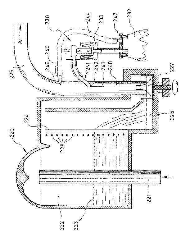
図4では、同じ構成要素は図2の参照番号と同じ番号で確認されるが、番号が200増加している。乳は矢印Aの方向に流出ダクト226を介して乳流れ測定装置220から移送される。抽出用細管241が、流出ダクト226の鉛直部分240の中へ突出し、下方に向けられた、241の自由開口242は、流出ダクト226の自由断面積に比例して50乃至100倍或いはそれ以下の比率である。流出ダクト226の中で移送される乳ピストン或いはピストン状ストッパーが、一様な形態を常に有してはおらず、さらに例えば、各ピストンから乳の分離の可能な限り正確な比例量を達成するために、それらは導線パイプの中間部よりダクト226の内側で全く長く形成できるので、自由開口242の中間243は、流出ダクトを自由端242のようにの幾分円形断面と仮定するとき、流出ダクト226の内壁から内径の1/3の距離に位置するように配置される。乳サンプル抽出装置230が継続して開放しているなら、分析サンプルボトルへ流入する乳流れは、乳流れに依存し、並びに厳密に再生可能だが、乳流れの量は、比例しないであろう。乳流れの量を比例させるために、乳流れは対応する特性曲線に従って弁で制御されなければならない。しかしながら、50ml以下のサンプル量の分配或いは分離のために、細管の断面を使用しなければならないので、測定は極端に不正確で、さらに克服しがたい洗浄の問題が起こる。
【0017】
この装置も又、乳の分離が等圧力の下で行われ、分析サンプルボトル232は点線だけで示すダクト244及び流出ダクト226の内部に突出するパイプ245を介して、乳の真空となお連結されている。パイプの開口246が乳の流れからそれているにも係わらず、乳が分析サンプルボトルへ達するの防止するために、せいぜい径0.5mm乃至0.8mmの極小のボア247が、ダクト244内に設けられる。ダクト244内の乳の貫通が、最初から防止されるように、開口は、空気の軽い流れがボア247からダクト244を通って流出ダクト226へ起こるように寸法決めされる。一方、開口247は又、分析サンプルボトル232の内部は、乳絞りの真空に保持されるべきだから、ダクト244内に真空の喪失が実際的に起こらないように小さくすべきである。この開口はダクト244の始点で、パイプ245の近くに取り付けられるのが好ましい。
図5は、図4に示す乳サンプル抽出装置に関する乳サンプル抽出装置の変形例を示す。残った同じ部品は300増加した番号で確認される。これらの部品は再度詳細に説明はしない。
流出ダクト326内に突出するパイプ341は、分岐部350によって2つのダクト351と352に分けられ、ダクト351が乳サンプル抽出装置330とダクト351の端353とを経て乳流れ測定装置320の乳サンプ325と連結される。他のダクト352は、乳サンプル抽出装置330を介して分析サンプルボトル332と連結される。乳サンプル抽出装置330は、図10の援用で個々に詳細を示すような逆止弁からなる。
【0018】
図6は、図2乃至図4のこれらの実施例に関連する乳サンプル抽出装置の実施例を示す。乳サンプル抽出装置430が、上側401が乳流れハウジングの下側に接し、検量開口31が流路開口402と整列するように、乳流れ測定装置20の下側に取付け可能である。流路開口402の下部は永久磁石から、或いは強磁性材料のいずれかから作られるリング形状の本体403によって形作られる。シリコン或いはポリウレタンのような衝撃吸収材料から作られた偏向板404が、本体403の下側に接している。他の条件が変わらないままである場合には、永久磁石の吸着力は、このプレートの厚さによって正確に調整することができる。偏向板は、流路402と整列し、少なくとも同じ大きさである開口405を有する。偏向板404の代わりに、本体403の下側に直接固定された吸収層も又、設けることができる。高さD及び開口405の直径より大きい直径を有する略円筒の中空キャビティ406を、偏向板404の下に設けるのがよい。この高さDは、弁の全リフトより短い。直径は移動シール部分より幾分大きい。これによって以下に詳細に説明する弁のピストン作用を生じる。中空キャビティでは、本体は案内され、鉛直方向に移動する。本体407は、円筒本体であるのが好ましいが、流路402を密封するために、第1上部位置において、偏向板404に対して漏れ止めできる頂面409を単に有する限り、中空キャビティ406内で可動な別の形状の本体も、設けることができる。図6に示すように、シール本体407は、円筒中空キャビティ406を横切って延びる鋼性ワイヤ411から作られ、例えばシリコン材料から作られた、運動を吸収するためのカバー412を有するバッファー410上の第2下部位置に静止する。シール本体407は、永久磁石材料から作られるのが好ましい。
【0019】
電磁コイル413が、円筒中空キャビティ406の軸線と同軸に配置され、電気線414を介して負荷することができる。
凹部415及び416(図6)が、円筒中空キャビティ406の側壁に、高さDより下に設けられ、図6に示すシール本体407の第2下部位置では、円筒中空キャビティの内部スペース406と接触し、しかも下端が排出ダクト417と接触する。排出ダクトはその下端が、中空の貫通ニードル418の形状に形成され、例えばニードル418は、詳細に示さない分析サンプル管のベントプラグ419を貫通することができる。リング形状の突出部420が、中空貫通ニードル418と同軸に形成され、ニードル418はベントプラグ419の上側421に対してシールされるようになっている。この方法では、円形スペース422が、このリング形状突出部420とベントプラグとの間に形成されて、凹部423を介してダクト434と連結する。このダクト434は、図2に示すダクト34でもよく、或いは乳絞りの真空と連結される図3に示すダクト134でもよい。この方法では、ベントプラグ419の端418を貫通後、乳絞りの真空が、円形スペース422内に存在し、一方で分析サンプルボトルに生じる圧力増加をプラグ419のシールによって防止し、他方で、引込み乳によって圧縮された分析サンプルボトルの内部のガス容積が、サンプル抽出が等圧力の下で起こることを保障するように排気することができる。
【0020】
それを必要とするかかる状況では、弁は又、例えばピンチ弁として形成され、それによって、例えば管は締めつけられ、或いはそれぞれ解放される。
乳抽出装置の同様な実施例を図7に示し、同じ部品は、100増加した同じ番号で確認される。この図では、さらなる実施例が下部左半分に示され、ストッパー524がパイプの下端518に配置され、且つネジ525によってハウジング530に固定され得る。次いで、このストッパー524上には、対応するパイプ形状の分析サンプル容器を配置し、容器の内周は延長部526に対してシールされる。
別の実施例が図7の下部右半分に示され、2つのO形状のシールリング527がパイプ518の外側に支持され、次いで、分析サンプル容器は密封の仕方で直接押され得る。
図8及び図9は、乳サンプル抽出装置のさらなる実施例を示し、この実施例は図6に対応する乳サンプル抽出装置の簡単な変形であり、同じ構成要素は、図6のような参照番号だが、200増加した番号で確認される。この実施例では、電磁コイル613がシール本体607の下端に配置され、第2下部位置に見いだされ、シール本体の正確な開閉機能のための非常に安定したサポートとなる。ここで、シール本体は3つのガイドリッジ640、641及び642上で単に案内される。リッジ640とリッジ641及び642との間には、既に説明した凹部615及び616がそれぞれ、乳の流出のために設けられる。さらに、他方では平らな凹部643が、さらなる凹部644を介してチャンバ623と連結され、且つ乳絞りの真空の下に保持されるリッジ641と642との間に形成される。凹部644は、シール本体607の上端が又、第2下部開口位置で真空であり、乳の摩擦無しの排出が達成される効果(非ピペット効果)を有する。
乳と図2乃至図4及び図6乃至図9に説明した乳サンプル抽出装置との分離は、装置が開閉弁として機能するように行われるのが好ましい。図6に示すシール本体407の第2下部位置から始まり、例えば、正しい方向の電流及び強さが電磁コイル413に与えられるなら、偏向板404に当たる位置に来るまでシール本体407が上方に移動する。この第1上部位置では、同時の閉鎖位置はシール本体407によってダクト402を通る乳の流れの遮断に相当する。シール本体407或いはリング403のいずれかは、永久磁石で作られ、他のそれぞれのピースは強磁性材料で作られているので、シール本体407は、電磁コイル413がより以上の電流を運ばないときにも、この位置に保持される。弁の開放は、リング403とシール本体407との間の磁気吸着力に打ち勝ち、さらにシール本体を再びその第2下部開放位置に戻すために、反対向きの電流によって略同じ大きさのインパルスが電磁コイル413を通して送られるのを単に必要とする。この位置では、乳流れは、ダクト402を通って解放される。この第2下部位置では、この本体はバッファー410に載るので、同様にシール本体407に対する電磁コイルの吸着力の必要性はない。シール本体は直径6mm程度、長さ16mm(8mmのリフト長さ) の非常に小さい本体から作ることができ、ダクト402は閉鎖端で直径1.5mm 乃至3mm を有し、シール本体407の全容積は1.35ml、重量10g 以下であるので、シール本体407の慣性質量を非常に小さく保持することができる。従って、弁を開閉するために、1.5Watt 程度の最大電力を有する、長さ10ms乃至100ms の最も小さいインパルスを単に必要とする。これは、インパルス間でエネルギーは消費されないので、非常に高い作動サイクルでは、エネルギ消費が非常に低い( 代表的には、0.2Watt)ことを意味する。しかしながら、係る弁によって、企図した分離流れで0.05秒まで下げた開放時間が可能であることもなお重要である。
【0021】
弁を制御するために、反対方向の電流を有するインパルスを電磁コイルに供給して、電磁コイルにおける電圧の極性を逆にするのが好ましい。有用な実施例によれば、シール本体を第1位置から第2位置まで、さらに第2位置から第1位置まで移動させるために、装置は1つの電磁コイルの代わりに、反対方向に巻かれた2つの電磁コイルが設けられ、それによってインパルスが第1電磁コイルと第2電磁コイルに交互に供給される。
上述の装置は、好ましくはインパルス制御と関連して説明したが、それでも永久磁石の使用なしに、第1方向の電流がそれぞれ電磁コイルに供給され、シール本体がその位置の1つに保持される限り流れるように、シール本体用の強磁性材料を単に用いることによって装置を実行させることができる。シール本体を他の位置に移動させるために、電流の方向を逆にして、切り換えタスクが起こるまで電流を保持するのが好ましい。しかしかかる工程は、電流の消費及びコイルの熱負荷を増大させる。
図6に示す実施例では、あるピストン作用が距離Dに亘ってシール本体の運動中に生じる。かかるピストン作用は弁の作動にとって絶対的に必要ではないが、非常に有利であるのがわかっている。
【0022】
弁の中に組込むことができるピストン作用の結果は、以下のようである。
シール本体の閉鎖によって、その頂面は円筒形状の中空キャビティ406内でピストン状に長さD移動する。それとともに、この円筒キャビティ内の乳が移動し、分離又は分割流路402が後方から自由に送られ、その結果次の分離サイクルが最適に交換される効果を果たす。これはさらに、代表的なサンプルを改善する。同様に、ピストン作用によるこの自由な送りは、各分離サイクル前に、実際のダスト粒子からの開口31、131を含む分離流路の完全な洗浄を引き起こす。装置の洗浄段階では、この作用はなおさらに増大し、弁の切り換え周波数(例えば、90-120 S/min) を非常に増加させることによって、さらに使用される。
閉鎖運動に続くシール本体の開放運動では、乳流れが円筒長さDの端でシール本体の頂面を経て凹部415、416を通って分析ボトルまで流れ去る前に、乳は同じピストン作用によって分離流路から吸引される。弁の開放によって吸引され、弁の閉鎖によってそれぞれ押し戻される乳の容積は、同量で、従って分離量に影響を与えない。この乳容積の前後の押し出しは、円筒部分Dの有効長さに単に依存し、かかる場合にはピストンとシリンダとの間の円形ギャップにも依存する。同様に、シール本体の全リフトは乳は最終的に凹部を経て流出することができるだけなので、長さDより相当大きくなければならない。シリンダ(例.直径6mm、長さD 5mm)の小さい寸法に基づく。乳の毛管引力及び結合力が、強く作用するので、鉛直位置のシリンダは次の閉鎖段階前に常に乳で満たされる。シール本体の加速運動は開閉によって変化し、これは2方向の運動に対してコイルへの変化する電流の強さを設定することによって修正することができる。
【0023】
しかしながら、説明したピストン作用の最も重要な利点は以下のようである。常に比例する量のサンプルと、可能な限り小さいキャリーオーバエラー並びに可能な限り低いリザーバ高さを実現するために、弁の流れ貫通開口405より上の分離流路は可能な限り短くあるべきである。これによって、特に低い乳流れでは、非常に小さい静水圧(代表的には、0.5cm 乃至2cm 水頭) を生じる。又、動的分離装置(例えば、図4及び図5参照)による増大圧力は、低い乳流れでは非常に小さい。このような低い静水圧及び動圧では、乳の毛管引力、結合力及び壁力は有用になる。その結果は、従来の開閉弁(ピストン作用なし)の流出開口405の開放後の分離流れの不規則で、不正確で、且つゆるやかな開始である。説明したピストン作用はここでは非常に低い静水圧と動圧の状態で、分離流れのゆるやかで、不正確な開始動作に打ち勝つための援助として特に作用する。第1に、この方法では、低い乳流れでは小さい分析ボトルに直接満たされるべきで、代表的なサンプルにとって必然的に必要であるように、最も小さいが再生可能な分離量に対するサイクル当たりの非常に短い弁開放時間が可能にされる。
静水圧及び増大圧力の増加とともに、分離流れは毎回自発的に、且つ直接的に開始し、ピストン運動の分離の流れは容易に且つ抵抗なく従うので、ピストン作用は自動的により空作動する。従って、自然な漏洩は高圧力で幾分邪魔される。
【0024】
与えられたピストン作用の算入のもとで正確な漏洩部分は、実験的に最も良く決定される。これととともに、例えば、実験室では静水圧或いは動圧(例えば、0.5 、1.0 、2.0 、4.0 、8.0cm 水頭) のレベルを変化させるための及び対応する乳流れ(例えば、0.1 、0.25、0.5 、1.0 、2.5 、5.0 、9.0 、12.0L/min)のための具体的な装置の調整のために可能性が設定される。分離された量は各レベルに対して検出され、分離サイクル当たりの弁開放時間と分離サイクルの数との組み合わせを変えることによって生じる。同時に、毎分の弁開放時間とサイクル時間の発生、即ち開放時間(S/min) が一定に保持され、それぞれのレベルに対する理論的な分離量がそれぞれ一定であることを意味するのが重要である。
実験的に、しかしながら、個々のレベル内の実際の分離量は、常に同じ量ではない。特に、低圧及びそれぞれ低い流れのレベルによって、制御ファクター、弁開放時間/ サイクル及びサイクル/ 分の数の変動の組み合わせの変化が生じ、開放時間が常に厳格に一定に保持されるとしても、期待するような一定の分離量ではない。従って、短い弁開放時間( 対応するサイクル/ 分の高い数) によるそれぞれの同レベルでは、分離量は長い弁開放時間( 対応するサイクル/ 分の低い数) によるものより多い。この結果は、明らかにサイクル数/ 分( 対応する減少する弁開放時間) の増加とともに、ピストン作用がより有効であり、低いレベルにおける各弁開放時間とともに分離流れのゆるやかな開始に単純な加速援助をすることと結びつく。これらの関係を特性図( 分離量、弁開放時間、圧力及びそれぞれの流れレベル) として表すために、低いレベル( 例えば、乳流れ250ml/min)では、弁開放時間は例えば、0.1 秒と0.25秒の間の範囲で、分離量は実際に一定で、非常に良好な再現性を有する。しかしながら、分離サイクル当たりの長い弁開口時間の増加とともに( 対応する小さい分離サイクル) 、分離量は徐々にその大きさが減る。これの条件の下で、ピストン作用の周波数は、再現可能な安定分離流れを保証するために、これ以上十分でない。慣性に基づく分離流れの開始の問題は、高い乳流れ及びそれぞれの圧力の増加とともに徐々に減ずるので、最終的には、高いレベル内で、弁開放時間とサイクル/ 分の数との技術的なあらゆる組合わせは、一定で、且つ非常に再現性のある分離量を生じ、これは理論的な計算と一致する。従って、この観点から、高いレベルでは弁制御ファクターに対する領域を制限するのはこれ以上必要でない。
【0025】
開閉運動の周波数に言及すれば、定められた開放時間と閉鎖時間( いっしょでサイクル時間を生じる) とを有する毎分120 サイクルが、定められた分離流れに対して絶対的に実現可能である。しかしながら、このタイプの高いサイクル数は、磨耗の開始を増加させ、これに関連して発生する騒音レベルがそれに比例して高いという欠点を有する。従って、弁は、時間当たり低いサイクル数、例えば、毎分30サイクル以下で作動されるのが好ましい。
可能な限り代表的で、且つ乳流れのあらゆる条件のもとでキャリーオーバを有しないサンプルを得るために、供給ライン402の容積は出来るかぎり小さく、且つ開口当たりの分離された乳量とほぼ同じ大きさに保持され、或いは容積402では、全乳流れに相当する一定の乳の交換が起こるようになっているべきである。これに関連して、乳サンプル抽出装置は、供給ライン402の断面のできるだけ短い開放時間を比例して大きく選択できることに基づいて、それに比例した大きな分離流れが可能であること、さらにそれにもかかわらず、各開閉ステップによって、ライン402からの乳は液送して戻され、新しく吸引され、その結果新鮮な乳が乳流れから分離されるので、代表的なサンプルが得られるという重要な利点を有する。
【0026】
図10は、図5に概略的に示した乳サンプル抽出装置を個々に詳細に示す。ダクト351と352は、ハウジング内に形成された実質的に円筒の中空キャビティ361に通じる。ダクト351と352の開口に対向する中空キャビティの側壁には、最初に述べたダクトと整列した流出ダクト362、363が設けられている。中空キャビティ361には、中空キャビティ361と実施的に同じ断面積を有する円筒形の永久磁石364が同様に設けられる。永久磁石は、中空キャビティ361内をその軸線に沿って、右端がダクト352と363の端をシールし、ダクト351と362の端を開放する、図10に示す第1位置と、図10の左端がダクト351と362の端をシールし、ダクト352と363の端を開放する、図10に示す第2位置との間で移動可能である。ハウジング360内には、2つの強磁性本体365と366が、円筒形の永久磁石364の軸線上に、それぞれ第1位置、第2位置から一定の距離を隔てて配置されている。知られた本体は、各々プラグ形状部品367と368に保持され、各々コアの運動を低下させる材料から作られる。永久磁石364のその第1位置から第2位置への、さらに第1位置へ戻る運動によって、磁石はそれぞれこれらのプラグ形状部品に当たる配置になる。電磁コイル369が、永久磁石364の軸線と同軸に配置される。電磁コイル369によって送られる、対応する大きさの、好ましくはインパルス状の電流の援助によって、電磁石はその第1位置から第2位置へ、さらに第2位置から第1位置へ移動することができ、それによって永久磁石は、電磁コイルを通るさらなる電流なしに、強磁性本体366と365への磁力によって保持される。
【0027】
図5と関連して図10に示す乳サンプル抽出装置は、それぞれの乳流れから一部が連続的に分離され、永久磁石364は図10に示す位置にあるとき、分岐部350とダクト351、362を通って乳サンプ325内に返流するという利点を有する。この乳流れは、永久磁石が第2位置へ移動するとき遮断され、乳サンプル分離流れはダクト352と363を通って、分析サンプル容器の中へ流入することができる。分岐部350と、ダクト351、352の容積をできるだけ小さく保持することによって、中空キャビティ361に通じるダクト351には、乳が実際に常にそれぞれの乳流れに相当しそれによって、代表的なサンプル抽出が確実にされ、低い増大圧力による分離流れの開始の問題が起こらないことを保証する。
乳サンプル抽出装置と、前述したタイプの弁とを使用する本発明による方法を実施するために、以下の所見及び決定が仮定される。
(a) 分析サンプルホルダーでは、20mlと40mlの間の乳量を期待値E 、即ち、乳絞りされる牛の全乳量(kg 又はml) から独立して分離すべきである。所見のために、30mlの分離した全サンプル容積が仮定される。
(b) さらに、分離された部分的な量をそれぞれの乳流れに比例して取るべきである。
【0028】
これらの仮定のもとで、全サンプル量に達するために、以下のように分離されなければならない。
分離容積/ 時間(ml/min)= 全サンプル(ml)/ 期待値(ml)×乳流れ(ml/min) (1)
今から、連続的に開放した弁、即ち分離流れ100%(例えば図2と図3の装置に一致する)で分離流れ(ml/min)を決定するなら、分離流れ100%(連続的に開放した弁に対して)は、底部開口31と決定した断面積Aを有する131を通って流れ、蓄積或いはリザーバ高さH(及びそれぞれの静水圧)の機能は、以下の式に一致する。
分離流れ(100% )(ml/min)= 60×μ×SQR(2 ×g ×h) (2)
ここに、g = 重力加速度(cm/S2)
h = リザーバ高さ(cm)
A = 底部開口の断面積(cm2)
μ= 流出修正係数 0.63
SQR=平方根
リザーバ高さ、即ち乳流れの変化による静水圧が変わらなければ、分離流れ(100%) は一定である。これは、例えば、一定リザーバ高さH=2cm 、開口直径0.15cm、これから底部の開口面積A =0.0176cm2に対して、一定分離流れは、41.67ml/min となる。
【0029】
乳流れの大きさがリザーバ内で幅S ( 例えば、図2 の実施例に示すような) の鉛直方向に延びる測定スリットの前のリザーバ高さ( 及び静水圧) によって測定されるなら、以下の関係を生じる。
乳流れ(ml/min)= 60×μ×S ×2/3 ×SQR(2 ×g)×h3/2 (3)
ここに、 g =重力加速度(cm/S2)
h =リザーバ高さ(cm)
S =スリット幅(cm)
μ= 流出修正係数 0.63
SQR=平方根
式(2) に関連して、乳流れに依存する分離流れ(100%) を以下のように決定できる。
分離流れ(100%)= 60 ×μ×A ×SQR(2 ×g)×[(乳流れ)/(60 ×μ×2/3 ×SQR(2 ×g)]1/3 (4)
スリット幅S=0.25cmで例えば、一定であるとし、開口断面積A=0.0176cm2(=1.5mmの開口直径) に対して、理論値の表が以下のように計算される。
【0030】
開放時間(s/min)=( 分離容積(ml/min)×60s)/(分離流れ100 %)(ml/min)
(5) これから、必要な開放時間( 秒/ 分)(一定なリザーバ高さ) は表2のようになる。
60 s/min 以上の値は可能でないから、このことは、実現可能な開放時間に達するために、一定の分離流れ( ここに41.67ml/min)は、少なくとも1.5 倍増大しなければならないことを意味する。これから、しかしながら最も短い開放時間は0.1 s/min 以下に落ち、サイクル当たりの個々の弁の開放時間を0.1 秒よりずっと小さくし、その結果技術的に実現が困難となる。
【0031】
一方、リザーバ高さを変えることによって、必要な開放時間(秒/分)は以下のようになる。
【0032】
これらの理論的な開放時間に従って進めようとするなら、例えば、高い乳流れと低い期待量によって、比較的長い開放時間が生じ、その間もちろん乳流れがすでに相当変化しており、代表的なサンプルが抽出されないという困難性が存在する。一方、低い乳流れと高い期待値によって、非常に短い開放時間が生じ、その間分離容積/ 時間の間の仮定した比例関係がなお存在するかははっきりしない。
従って、本発明によれば単一の開放時間( 秒/ 分) は制御されないが、この開放時間は、サイクル当たりの対応する短い弁開放時間を有する、複数のサンプル採取サイクルに分けられ、さらに弁のそれぞれの開放時間は制限した範囲内を単に変化して進み、その範囲内では分離流れは時間に比例することが確実である。実際の制御が、まっさきに行われ、採取すべき毎分のサンプル容積が、各々分離サイクル当たりの短い弁開放時間を有するサイクル数で抽出され、それによってサイクルはそれぞれ弁開放時間と分離サイクル当たり弁が開放していない時間とからなる。その後は、制御が行われる分離サイクル数は、以下のように決定することができる。
開放時間( 秒/ 分)= 分離サイクル数(n/ min)×分離サイクル当たりの弁開放時間( 秒) (6)
今、上述したタイプの弁で実現可能な分離サイクル(n/min)の数は制限される。実際に、n=120 の上向きの分離サイクルの数は達しやすい。しかしながら、磨耗と高い騒音レベルの理由から、分離サイクル数はn=30/minに制限されるのが好ましい。下限に向かって、分離サイクル数は同様に乳流れが低い乳絞りの終わりに向かって、代表的なサンプルがなお抽出されなければならない点で制限される。乳成分の物質、特に乳の脂肪成分は乳絞りの終了に向かって相当変化するので、これは特に重要である。乳絞りの終わりに向かう脂肪成分は、乳絞りの最初より相当多い。これから、分離サイクルの数は毎分2 乃至3 以下に低下すべきでないことが導かれる。
【0033】
図3 に示す対応する実施例、一定の静水圧で測定されるなら、カバーされる変化範囲が大きいために、一定の弁分離時間によって毎分のサイクルカウントの変化に基づいて単独で十分な変動を行うのは可能でないだろう。
さらに、時間当たりのサイクルカウントに対する境界値が達した場合には、長い或いは短い弁の開放時間への切替えが行われなければならない。一定の静水圧における測定のために、静水圧によって生じた乳高さは、あらゆる種類の乳流れ(特に乳絞りの終わり)に代表的なサンプル抽出を達成するために、そんなに大きくてはならない。低い静水圧によって、ここでは毛管引力と結合力が特に重要であるので、分離流れが弁開放時間の狭い範囲にだけ亘って一定となる。図3による一定の、低い静水圧のもとでの作動では、広範囲の弁開放時間を達成するために、弁開放時間当たりの分離容積の較正曲線を作り、次いでサイクル当たりの必要な弁開放時間を計算するためにプロセッサに入力するのが必要になり得る。
乳サンプル抽出装置が図2に示す装置で作動し、リザーバ高さが乳流れに依存して変化するとき、単一のサンプル抽出装置によって全測定範囲をカバーすることを一層有利に行うことができる。この場合には、表3 から理解できるように、開放時間の比率( 最大値:最小値が122 :1)の減少をすでに生じる。これは、リザーバ高さ、即ち静水圧であるそれぞれの乳流れによる測定範囲の減少がすでに起こり、さらにそれに含まれるのは、乳流れに依存するそれぞれの開放時間の減少である。この場合、サイクル当たりの弁開放時間の範囲は、0.1 秒乃至0.8 秒の狭い範囲に制限され、この範囲では分離流れは時間に比例することが保障される。すでに上述したように、この場合しかしながら、低いリザーバ高さと低い静水圧に相当する小さい乳流れによって、分離流れと開放時間との間に比例関係を保証するために、狭い弁開放時間間隔が選択される必要性を生じる。表4 から理解できるように、
【0034】
それぞれの制御範囲は、例えば、表4 に従って、先ず第1 にレンジデータとしてプロセッサに入力される。分離サイクル当たりの一定の弁開放時間に対する分離サイクル数の計算はそれぞれ、測定された乳流れに依存してプロセッサによって行われる。対応する範囲の境界に達する際、分離サイクル当たりの弁開放時間と関連して、対応する分離サイクル数の対応する切り換えが発生する。もちろん、サイクル数と弁開放時間との最適な関係を可能なかぎり維持するために、対応する範囲の境界に達する前にかかる切り換えは又、発生し得る。
上述のタスクは例示のためだけにあり、0.0176cm2 の流れ貫通開口31と131 の流出断面にそれぞれ当てはまる。
以下では、例を援用して、分離サイクル数と、分離サイクル当たりの弁開放時間がいかにして計算され、選択されるかを示す。
設定許容値E(全乳量) は、10,000mlである。
所望の全サンプル容積は30mlである。
測定された瞬時の乳流れは2500ml/minである。
式(1) から、毎分の必要な分離容積を7.5ml/min と計算することができる。次いで、式(4) から分離流れ(100%) を61.15ml/min として計算することができる。
【0035】
次いで、式(5) から開放時間は27.36S/minとなる。表4 から、仮定した瞬時乳流れでは、毎分の分離サイクル数は15として計算することができる。これから、サイクル当たりの弁開放時間は、式(6) からサイクル当たり0.49秒となる。表4 によれば、分離サイクル当たりのこの弁開放時間は可能である。
サンプルの抽出を制御するためのプログラムはなおさらに改良することができる。例えば、図2 乃至図5 に示した乳流れ測定装置によってすでに流れたそれぞれの乳量が又加えられ、従って、時間間隔で流れたそれぞれの乳量は、より正確に決定することができる。従って、乳絞り段階では、乳流れが、およそ200ml/min の低い値で最初に始まり、これからかかる状況では30秒のサイクル時間が現れる。次いで、乳流れが比較的強力に増大するなら、取られた分析サンプルは不正確になる。知られたセットアップによって30秒後にサンプルの分離が最初に起こり、それによって今回は単に100ml の乳容積が流れたと仮定されるので、分離サイクル中現実に流れた乳量の同時の確実な測定によって修正を行うことができ、30秒のサイクル時間の満了前に100ml 以上の乳が流れたことが乳量の測定によって確立されるとき、弁開放時間のサイクル時間の新しい調整が必要とされる。
【0036】
乳流れの時間当たりの変化が所定のしきい値をオーバシュートするとき、新しいサイクル時間或いは弁開放時間を決定するタイプの制御を与えることができる。
サイクル時間及び弁開放時間の決定は、図4及び図5による装置によって実施される方法と同じ方法で行われる。これに関連して、弁が完開の状態における分離流れ(100 %) は、ダクト241 、341 を通る流れに相当するだけの単なる違いを生じる。しかしながら、この分離流れ(100 %) は、これらのダクトの入口開口の断面の、乳の移送用のダクト226 、326 に対する関係に依存する。さらに、この分離流れ(100 %) は、乳流れに依存し、且つほとんど再生可能だが、その量に比例はしない。分離流れは実験的に決定された特性曲線の形態で最も良く表される。弁の洗浄は、サイクルカウントの1 つが最大まで増えた状態で行うことができる。
【図面の簡単な説明】
【図1】本発明による方法及び乳サンプル抽出装置を採用する乳絞り装置の概略図である。
【図2】本発明による乳流れ測定装置並びに乳サンプル抽出装置の概略断面図である。
【図3】本発明の別の装置による乳サンプル抽出装置を有する乳流れ測定装置の概略断面図である。
【図4】本発明の別の装置による乳サンプル抽出装置が連結された乳流れ測定装置の概略断面図である。
【図5】本発明による乳サンプル抽出装置が概略的に示された、さらなる実施例が組合わされた乳流れ測定装置の概略断面図である。
【図6】本発明による乳サンプル抽出装置の実施例の縦断面図である。
【図7】分析サンプルボトル用の2つの異なる固定手段が単に別の部品で示される、図6に示す実施例と同様の、本発明による乳サンプル抽出装置の断面図である。
【図8】本発明によって形成された乳サンプル抽出装置のさらなる実施例の断面図である。
【図9】図8に示す実施例の線IX-IX に沿った断面図である。
【図10】図4に示す乳サンプル抽出装置の断面図である。
【符号の説明】
4 移送ダクト
9 プロセッサ
20 乳流れ測定装置
22 測定チャンバ
24 測定スリット
25 サンプ
26 流出ダクト
28 センサー
30 乳サンプル抽出装置
32 分析サンプルボトル
34 導線[0001]
[Industrial application fields]
The present invention extracts from a milk stream squeezed from a cow an amount of analysis sample proportional to the milk squeezed milk, thereby providing a sample portion from a predetermined milk stream dependent on the milk flow. A method for extracting a quantity, as well as a milk flow measuring device arranged in a milk squeeze duct, and a processor unit for controlling the milk sample extracting device connected to the analysis sample container and in contact with the milk flow The invention relates to a milk sample extraction device for carrying out this method.
[0002]
[Prior art and problems to be solved by the invention]
The quality of milk, and hence the price per kg, is devoted to its content, in particular the proportion of the fat component of milk. However, if milk is allowed to stand for a certain period of time, the fat component is preferably deposited on top of the milk in this case, making the determination of the fat component very difficult. Therefore, there are very strict regulations on so-called typical analytical sample extraction methods that should not normally be greater than 50 ml. This method is very laborious, labor intensive and time consuming.
A sample extraction device is already known from
[0003]
Utility Model G 85 02 2594, on the other hand, relates to a milk transport device for a milk transfer operation installed in a tank truck or dairy farm. In the same way, the amount of each sample to be extracted should be extracted. By defining the total amount of sample and the partial amount of sample with respect to the time at which it is extracted, the number of partial constant amounts of sample to be extracted is made constant. However, the transfer of the whole milk flow can cause differences in the total milk flow, so that the rest interval between the two partial sample extractions varies depending on the respective milk flow, so It has been suggested to consider the relationship to each measured milk flow. However, the milk flow changes that should be expected and consequently considered are relatively small.
In DE 32 10 465 it is known to extract a proportional amount of milk from the milk flow that occurs directly during milking. In this case, it is connected to a milk flow measuring device that flows milk that has been squeezed, and the partial quantities are each branched with the aid of a peristaltic pump, and the operating speed of the peristaltic pump is determined according to the measured milk flow. Alternatively, it is controlled depending on the height level measured by the milk flow measuring sensor. However, such a device is useful only when the range of milk flow to be generated is defined, so that, in particular, peristaltic pumps do not guarantee more accurate sample extraction at high milk flow. In addition, peristaltic pumps have a very limited life, especially at high operating speeds, and the pumps have a relatively high energy consumption which is further increased by having to operate between vacuum and atmospheric pressure.
[0004]
The same drawback is
As already mentioned, so-called representative samples are mainly made for the accurate determination of the milk component of the milk yield. However, when milk is allowed to stand, fat has a tendency to deposit relatively quickly from the rest of the milk portion, so a sophisticated, long and accurate to extract a representative sample from milk that has already been set aside. A method of operation is required.
Such a method is of course unnecessary if such a representative sample can be extracted directly from the cow's milk squeeze, ie when the milk is not yet at rest. This method is also desirable in view of the fact that each cow is specifically monitored and the milk components of the milk are determined separately. However, the difficulty of such a method is less than 50 ml each time, regardless of the significant variation in milk flow and the time during each milking from cow to cow, despite the fact that the total amount of milk varies considerably from cow to cow. Only small bottles of analytical samples are available and are based on the typical sample being injected directly into the small bottle.
The expected value of total milk in cows already differs between 5 and 30 kg, ie in a ratio of 1: 6, and the milk flow that can occur during the milking stage is between 0.1 and 12 kg per minute, ie 1 It can vary at a ratio of 120. Combining both the milk squeeze amount and the effect on milk flow together can give rise to a wide range of possible changes at a ratio of 1: 720. At the same time, taking into account that the volume of the analytical sample can vary between 20 ml and 40 ml, i.e. at most a 1 to 2 ratio, when the main influencing factors are taken into account, the variation range to be covered by this is 1 It will be 360.
[0005]
To date, the proposed pumps cannot solve these problems. Peristaltic pumps that carry a certain volume by means of a pinch of the tube can only reach a maximum speed range of 1: 100, and in this case expensive iso-current control is required, so it is in the range of 1: 360. Cannot be controlled over time. In particular, it is necessary to control an equal current motor in a low speed region, but this motor is very problematic. Apart from this, this type of peristaltic pump, apart from the relatively high energy consumption, requires a large weight and a large construction volume, so it is not very suitable for transportable measuring devices used in cattle. Not in. In addition, the required tube elasticity changes with time, thereby changing the volume transferred at the same time, so the lifetime of this tube is short.
In the same way, an electromagnetic pump operated by a membrane cannot cover the required range of 1: 360. Similarly, in operation, the milk tends to stick to or collect on the valve, i.e. the risk of card ring is increased, so it is necessary to connect the valve to such a pump, thereby causing sufficient cleaning problems. is there. Finally, such electromagnetic pumps also have a relatively high current consumption.
Accordingly, the present invention is directed to obtaining a method and apparatus that can separately take a representative analytical sample of 50 ml or less for each cow during milking.
[0006]
[Means for Solving the Problems]
This is because by using a cycle-controlled valve, every cycle has a valve opening time and a valve closing time, which is obtained by experience of the total amount of milk to be milked from a particular cow. In order to simply extract an analytical sample held below a maximum predetermined volume of 50 ml from the expected value, the cycle time and valve opening time are determined, so that the cycle time and valve opening time are within a predetermined range of values. In order to avoid that the valve opening time or cycle time value is controlled depending on the milk flow, and that the value of the valve opening time or cycle time exceeds the range as a result of the milk flow change. This is achieved by the method of the invention of the type described above in which the valve opening time and the cycle time vary at the same rate as the values in the range.
In such a method, a representative analytical sample can be extracted from a large range of expected total milk, which is a possible milk flow between 5 kg and 30 kg and between 0.1 kg and 12 kg per minute.
To make this method easier, a partial amount of the separated sample is kept under the same pressure as the milk flow itself.
[0007]
For ease of control, the height of the milk reservoir is preferably kept constant above the valve to produce a separate flow that is substantially independent of the milk flow.
On the other hand, in order to change the separated flow through the milk flow dependent valve, the measurement area is still stretched when the method is implemented such that the milk reservoir height, which depends on the milk flow, respectively, occurs above the valve. Can do.
The range of values for cycle time, which can vary, is determined only by the controllability of the regenerative milk separation of the valve, so that its lower bound is practically determined to yield a more representative sample. The other end is determined by the number of samples to be extracted with a small milk flow and is preferably between 0.5 and 30 seconds (120 to 2 cycles per minute). However, the value range is preferably between 2 and 30 seconds.
The range of values for the valve opening time is determined by the inertia of the valve, as well as short opening times, and can be achieved with a constant milk flow, with an upper opening time meaning up to these opening times.
In this case, the range of values is between 0.05 and 1.2 seconds, preferably between high milk flow and 0.1 and 0.8 seconds respectively, with very low milk flow between 0.1 and 0.25 seconds. Can be reduced to range.
[0008]
As is known, the fat content of milked milk increases towards the end of the milking. As a result, milk viscosity and flow behavior change slightly. In this connection, the effect of capillary attraction can also be significant. For these reasons, it is useful for finely calibrating the fat component contained in the analytical sample with a gradual decrease in milk flow towards the end of the milk squeeze, and a gradual increase or decrease in valve opening time.
The method is preferably performed such that during each valve closure, a portion of the milk flowing through the valve is pumped back and the method further includes each valve opening to accelerate the onset of milk flow. At the same time, it is preferable that the suction force be exerted on the milk. The present invention also provides a milk flow measuring device disposed in the milk duct for performing the method and a processor for controlling the milk sample extraction device connected to the analytical sample container and in contact with the milk flow. A milk sample extraction device having a unit, the milk sample extraction device having an electromagnetic control coil, with the coil the seal body closes to a first position closing the flow through opening for sample extraction flow, and this opening is open Characterized by being movable to a second position.
The seal body is made from a permanent magnet or ferromagnetic material near the flow through opening, and the body made from the ferromagnetic material or permanent magnet is placed with the seal body in its first position. Is preferred. This embodiment enables energy saving operation because a simple change to a short impulse is required to move the seal body from its first position to its second position or from its second position to its first position. To do. As a result, it can be carried out by impulses of a short time of 10 msec to 100 msec, and currents in opposite directions are guided to the respective impulses. The change in current direction can be done, for example, by simply reversing the polarity of the voltage at the end of the electromagnetic coil, which can be done with the aid of electronic control.
[0009]
To be precise, it has been found that the seal body is particularly useful when made from a cylinder guided by a transverse guide. The body, in particular the guide, is preferably made from such a material that produces as little friction as possible between the guide and the body, or has a cover of such material.
Pipes that determine the flow through opening for sample extraction flow are useful when forming a body formed from a ferromagnetic or permanent magnet.
For optimum sealing and also to reduce operating noise and to further extend the life, the end of the seal body and / or the flow through opening facing the seal body has a layer of absorbing or damping material. Such damping material can be made, for example, from a silicon or polyurethane plate, or in the form of a steel spring coated with silicon.
In order to increase the safety of operation and the accuracy of operation, the electromagnetic coil is arranged at the height of the second position of the seal body.
In order to facilitate the complete discharge of a certain quantity of milk, a sample extraction specific duct is provided separately from the extraction of the sample under equal pressure, on the one hand connected to the milk squeeze vacuum and on the other hand the milk sample Leads to the end of the extractor. This expels air from the analytical bottle, which is expelled by the milk injection. This method ensures that the same pressure at which the milk sample is separated as well as above the milk flow, ie the milk pressure in the above case, also extends to the outflow end of the milk sample extraction device.
[0010]
In order to keep the risk of carry-over through the milk sample extractor as small as possible, on the one hand the space provided for the milk through flow is as small as possible, but on the other hand milk is easily drained and the milk sample extractor Is formed to be as clean as possible. An apparatus which has been shown to be advantageous is that the cylindrical seal body is movable along a guide path formed in a substantially cylindrical shape, with a recess extending in the longitudinal direction of the seal body on its surface facing the seal body. In contact with the flow through opening at the second position of the seal body and further with the end of the milk sample extraction device facing the analysis sample holder.
In order to achieve the full function of the valve, particularly with a short valve release time, as well as to prevent blocking, in particular the carding of the through-opening, the connection between the flow through-opening and the recess for sucking the flow Before reaching the closed position of the through-opening, it is useful to carry out the embodiment in such a way that, during the opening movement of the sealing body, the sealing body is interrupted by an adjustment movement over a predetermined distance (D).
According to a preferred embodiment, the milk sample extraction device is directly connected to a chamber in which a milk accumulation or reservoir corresponding to each milk flow is set. This chamber is preferably the corresponding chamber of the associated milk flow measurement sensor. In order to measure the height of the reservoir, an additional device is also provided in this chamber, for example a measuring probe arranged along the height at a distance from each other.
[0011]
According to a further embodiment, it is required to reduce the calculation and control costs when the milk sample extraction device passes up into the chamber and the milk flow is kept at a predetermined reservoir height in the chamber, respectively. . This is achieved, for example, by a corresponding connection and thus configuration with the milk flow measuring device, and is actually achieved in the so-called sump region.
In the embodiment described above, the separation is performed according to hydrostatic pressure, and the separation is also another embodiment in that the flow through opening of the milk flow sample extraction device is connected to a sample extraction pipe protruding into the milk transfer duct. Achieved according to In this case, dynamic sample extraction is performed.
In this case, it has proved useful to arrange the sample extraction pipe so that the longitudinal axis of the inlet opening is located at a distance of 1/3 of the diameter of the milk transfer duct from the inner wall of the milk transfer duct. Yes.
According to a preferred embodiment of the dynamic sample extractor, the sample extraction pipe is connected to the discharge lead of the analysis sample holder and branches in a first duct surrounding the outflow opening and in a second duct connected to the milk flow. The sealing body is movable and closes the outflow opening in its first position and opens the second duct, opens the outflow opening and the first duct in its second position, and further closes the second duct Is so movable.
[0012]
In the following, the present invention will be further described with reference to the embodiments shown in the drawings.
[0013]
【Example】
In FIG. 1, a cow's breast 1 is schematically shown with a
FIG. 2 shows a milk flow measuring universal device indicated by
[0014]
In the measurement and
A milk
The
[0015]
FIG. 3 shows a milk flow measuring device as well as a milk sample extraction device of the same type as in FIG. 2, whereby the same parts are identified by the same reference number, which is increased by 100. This embodiment differs in that a supply line to the milk sample extraction device is provided via a
In the embodiment described above, a milk sample extraction device is shown in combination with each milk flow measuring device. Instead of the milk flow measuring device as shown, of course other types of milk flow measuring devices having different operating principles, such as a milk piston analysis type milk flow measuring device or a volume activated type milk flow measuring device, Can be adopted. The coupling between the milk flow measuring device and the milk sample extracting device is of course unnecessary, but contributes to the compactness of the entire device. Of course, the milk sample extraction device can also be connected to a separate space through which the milk flows and accumulates at a predetermined height corresponding to each milk flow, or the extraction device can also be a space in the duct that transports the milk. And may be held constant at a predetermined height by the milk sample extraction device.
[0016]
With the above embodiment of the milk sample extraction device, the hydrostatic pressure generated by the accumulated milk plays a respective role for the separate flows entering the respective analysis sample bottles. On the other hand, in the two examples described below, milk separation occurs with the aid of the kinetic energy of the milk stream accelerated again from the milk sump.
In FIG. 4, the same components are identified by the same reference numbers as in FIG. 2, but the numbers are increased by 200. Milk is transferred from the milk
[0017]
In this apparatus, the milk is also separated under equal pressure, and the
FIG. 5 shows a modified example of the milk sample extraction apparatus related to the milk sample extraction apparatus shown in FIG. The same remaining parts are identified with a number increased by 300. These parts will not be described again in detail.
The
[0018]
FIG. 6 shows an embodiment of a milk sample extraction device associated with these embodiments of FIGS. A milk
[0019]
An
[0020]
In such situations that require it, the valve is also formed, for example, as a pinch valve, whereby, for example, the tube is tightened or released respectively.
A similar embodiment of a milk extractor is shown in FIG. 7, where the same parts are identified with the same number increased by 100. In this view, a further embodiment is shown in the lower left half, and a
Another example is shown in the lower right half of FIG. 7, where two O-shaped seal rings 527 are supported on the outside of the
8 and 9 show a further embodiment of a milk sample extraction device, which is a simple variant of the milk sample extraction device corresponding to FIG. 6, the same components being denoted by reference numerals as in FIG. However, it is confirmed by the number increased by 200. In this embodiment, an
Separation of the milk from the milk sample extraction device described in FIGS. 2 to 4 and 6 to 9 is preferably performed so that the device functions as an on-off valve. Starting from the second lower position of the
[0021]
In order to control the valve, it is preferable to supply an impulse with a current in the opposite direction to the electromagnetic coil to reverse the polarity of the voltage in the electromagnetic coil. According to a useful embodiment, in order to move the seal body from the first position to the second position and from the second position to the first position, the device was wound in the opposite direction instead of one electromagnetic coil. Two electromagnetic coils are provided, whereby impulses are alternately supplied to the first electromagnetic coil and the second electromagnetic coil.
The device described above is preferably described in connection with impulse control, but still without the use of permanent magnets, currents in the first direction are each supplied to the electromagnetic coils and the seal body is held in one of its positions. The device can be implemented by simply using a ferromagnetic material for the seal body so that it flows as far as possible. In order to move the seal body to another position, it is preferable to reverse the direction of the current and hold the current until a switching task occurs. However, such a process increases current consumption and coil heat load.
In the embodiment shown in FIG. 6, a certain piston action occurs during the movement of the seal body over a distance D. Such piston action is not absolutely necessary for the operation of the valve, but it has been found to be very advantageous.
[0022]
The result of the piston action that can be incorporated into the valve is as follows.
When the seal body is closed, the top surface of the seal body moves a length D like a piston in the hollow cylindrical cavity 406. At the same time, the milk in this cylindrical cavity moves and the separation or dividing
In the opening movement of the seal body following the closing movement, the milk is separated by the same piston action before the milk flow flows at the end of the cylinder length D through the top surface of the seal body and through the
[0023]
However, the most important advantages of the described piston action are as follows. The separation flow path above the valve flow-through
With increasing hydrostatic pressure and increased pressure, the separation flow starts spontaneously and directly each time, and the piston motion is automatically and idling because the separation flow of the piston motion follows easily and without resistance. Thus, natural leakage is somewhat disturbed at high pressures.
[0024]
The exact leakage is best determined experimentally, given the piston action. Along with this, for example, in the laboratory to change the level of hydrostatic pressure or dynamic pressure (eg 0.5, 1.0, 2.0, 4.0, 8.0 cm head) and corresponding milk flow (eg 0.1, 0.25, 0.5, Possibilities are set for the adjustment of concrete devices for 1.0, 2.5, 5.0, 9.0, 12.0L / min). The amount separated is detected for each level and is produced by changing the combination of the valve opening time per separation cycle and the number of separation cycles. At the same time, it is important to mean that the occurrence of valve opening time and cycle time every minute, that is, the opening time (S / min) is kept constant and the theoretical separation amount for each level is constant. is there.
Experimentally, however, the actual amount of separation within an individual level is not always the same. In particular, expect low pressures and low flow levels, respectively, to change the combination of control factor, valve opening time / cycle and number of cycles / minute variation, and the opening time will always be kept strictly constant It is not a constant separation amount. Thus, at each same level with a short valve opening time (high number of corresponding cycles / minute), the separation is greater than with a long valve opening time (low number of corresponding cycles / minute). This result clearly shows that with increasing cycles / minute (corresponding decreasing valve opening time), the piston action is more effective and with a simple acceleration aid for the slow start of the separation flow with each valve opening time at a lower level. It is connected with doing. In order to express these relationships as characteristic diagrams (separation volume, valve opening time, pressure and respective flow levels), at low levels (eg milk flow 250 ml / min), the valve opening time is, for example, 0.1 and 0.25 seconds. In the range between, the separation is actually constant and has a very good reproducibility. However, with increasing valve opening time per separation cycle (corresponding small separation cycle), the amount of separation gradually decreases. Under these conditions, the frequency of piston action is no more sufficient to ensure a reproducible stable separation flow. The problem of initiation of the separation flow based on inertia gradually decreases with high milk flow and the respective pressure increase, so ultimately, within a high level, technical issues of valve opening time and number of cycles / min. Every combination yields a consistent and very reproducible amount of separation, which is consistent with theoretical calculations. From this point of view, therefore, it is not necessary to limit the area for the valve control factor any further at a high level.
[0025]
Referring to the frequency of the opening and closing movement, 120 cycles per minute with a defined opening time and closing time (which together generate a cycle time) is absolutely feasible for a defined separation flow. However, this type of high cycle number has the disadvantage that it increases the onset of wear and the associated noise level is proportionally higher. Accordingly, the valve is preferably operated at a low number of cycles per hour, for example, no more than 30 cycles per minute.
In order to obtain a sample that is as representative as possible and has no carryover under all conditions of milk flow, the volume of the
[0026]
FIG. 10 shows in detail the milk sample extraction device schematically shown in FIG.
[0027]
The milk sample extraction apparatus shown in FIG. 10 in conjunction with FIG. 5 is partially separated from each milk flow, and the
In order to carry out the method according to the invention using a milk sample extraction device and a valve of the type described above, the following observations and decisions are assumed.
(a) In the analytical sample holder, milk volume between 20 ml and 40 ml should be separated independently from the expected value E, ie the total milk volume (kg or ml) of the cow to be milked. For observation, a separate total sample volume of 30 ml is assumed.
(b) In addition, the separated partial amounts should be taken in proportion to each milk flow.
[0028]
Under these assumptions, in order to reach the total sample volume, it must be separated as follows:
Separation volume / time (ml / min) = total sample (ml) / expected value (ml) x milk flow (ml / min) (1)
From now on, if the separation flow (ml / min) is determined with a continuously open valve, ie 100% separation flow (eg corresponding to the apparatus of FIGS. 2 and 3), the separation flow 100% (continuously open) ) Flows through the
Separation flow (100%) (ml / min) = 60 × μ × SQR (2 × g × h) (2)
Where g = gravitational acceleration (cm / S 2 )
h = reservoir height (cm)
A = sectional area of the bottom opening (cm 2 )
μ = Spill correction factor 0.63
SQR = square root
The separation flow (100%) is constant if the reservoir height, i.e. the hydrostatic pressure due to changes in milk flow, does not change. This is, for example, a constant reservoir height H = 2 cm, an opening diameter of 0.15 cm, and an opening area A at the bottom A = 0.0176 cm 2 On the other hand, the constant separation flow is 41.67 ml / min.
[0029]
If the milk flow size is measured by the reservoir height (and hydrostatic pressure) in front of a vertically extending measurement slit of width S (for example as shown in the embodiment of FIG. 2) in the reservoir Create a relationship.
Milk flow (ml / min) = 60 x μ x S x 2/3 x SQR (2 x g) x h 3/2 (3)
Where g = gravitational acceleration (cm / S 2 )
h = reservoir height (cm)
S = Slit width (cm)
μ = Spill correction factor 0.63
SQR = square root
In connection with equation (2), the separation flow (100%) depending on the milk flow can be determined as follows:
Separation flow (100%) = 60 × μ × A × SQR (2 × g) × [(milk flow) / (60 × μ × 2/3 × SQR (2 × g)] 1/3 (Four)
Slit width S = 0.25 cm, for example, constant, opening cross-sectional area A = 0.0176 cm 2 For (= 1.5 mm aperture diameter), a theoretical table is calculated as follows:
[0030]
Opening time (s / min) = (separation volume (ml / min) x 60 s) / (separation flow 100%) (ml / min)
(5) From now on, the required opening time (sec / min) (constant reservoir height) is as shown in Table 2.
Since values above 60 s / min are not possible, this means that a constant separation flow (here 41.67 ml / min) must increase at least 1.5 times in order to reach a feasible open time. means. From this, however, the shortest opening time falls below 0.1 s / min, and the opening time of the individual valves per cycle is much less than 0.1 seconds, which makes it technically difficult to implement.
[0031]
On the other hand, by changing the reservoir height, the required opening time (seconds / minute) is as follows.
[0032]
If you try to proceed according to these theoretical opening times, for example, high milk flow and low expected volume will result in relatively long opening times, during which the milk flow has already changed considerably, and a representative sample There is the difficulty of not being extracted. On the other hand, the low milk flow and high expectation result in a very short open time, during which it is not clear whether the assumed proportional relationship between separation volume / time still exists.
Therefore, according to the present invention, a single opening time (seconds / minute) is not controlled, but this opening time is divided into multiple sampling cycles with a correspondingly short valve opening time per cycle, Each of the opening times is simply changing and moving in a limited range, within which the separation flow is certain to be proportional to time. The actual control is done at once, and the sample volume per minute to be taken is extracted with the number of cycles each having a short valve opening time per separation cycle, so that the cycle has a valve opening time and a valve per separation cycle respectively. It consists of time that is not open. Thereafter, the number of separation cycles to be controlled can be determined as follows.
Opening time (seconds / minute) = number of separation cycles (n / min) x valve opening time per separation cycle (seconds) (6)
Now, the number of separation cycles (n / min) that can be achieved with a valve of the type described above is limited. In fact, the number of upward separation cycles with n = 120 is easy to reach. However, for reasons of wear and high noise levels, the number of separation cycles is preferably limited to n = 30 / min. Towards the lower limit, the number of separation cycles is also limited in that a representative sample must still be extracted towards the end of the milk draw where the milk flow is low. This is particularly important because the milk component material, especially the fat component of milk, changes considerably towards the end of milking. The fat component towards the end of milking is considerably higher than at the beginning of milking. This leads to the fact that the number of separation cycles should not drop below 2 to 3 per minute.
[0033]
The corresponding example shown in Fig. 3, if measured at a constant hydrostatic pressure, because of the large range of change covered, it is sufficient to vary by itself based on the change in cycle count per minute with a constant valve separation time It would not be possible to do.
Furthermore, when the boundary value for the cycle count per hour is reached, a switch to a longer or shorter valve opening time must be made. For measurements at constant hydrostatic pressure, the milk height produced by hydrostatic pressure should not be so great to achieve sample extraction typical for all types of milk flows (especially at the end of the milk squeeze). Due to the low hydrostatic pressure, the capillary attraction and coupling forces are particularly important here, so that the separation flow is constant only over a narrow range of valve opening times. For operation under constant, low hydrostatic pressure according to FIG. 3, a calibration curve of the separation volume per valve opening time is made to achieve a wide range of valve opening times, and then the required valve opening time per cycle. May need to be input to the processor to calculate
When the milk sample extraction device is operated with the device shown in FIG. 2 and the reservoir height varies depending on the milk flow, it is more advantageous to cover the entire measurement range with a single sample extraction device. . In this case, as can be seen from Table 3, there is already a reduction in the ratio of open times (maximum: minimum is 122: 1). This is because a reduction in the measuring range with each milk flow, which is the reservoir height, i.e. hydrostatic pressure, has already occurred, and it also includes a reduction in the respective opening times depending on the milk flow. In this case, the range of valve opening times per cycle is limited to a narrow range of 0.1 to 0.8 seconds, in which it is ensured that the separation flow is proportional to time. As already mentioned above, however, a narrow valve opening time interval is selected in this case, however, to ensure a proportional relationship between the separation flow and the opening time, due to the small milk flow corresponding to a low reservoir height and low hydrostatic pressure. Need to be generated. As you can see from Table 4,
[0034]
Each control range is first input to the processor as range data first according to Table 4, for example. Each calculation of the number of separation cycles for a constant valve opening time per separation cycle is performed by the processor depending on the measured milk flow. When the corresponding range boundary is reached, a corresponding switching of the corresponding number of separation cycles occurs in relation to the valve opening time per separation cycle. Of course, in order to maintain as much as possible the optimum relationship between the number of cycles and the valve opening time, such switching can also occur before the corresponding range boundary is reached.
The above task is for illustration only, 0.0176cm 2 This applies to the outflow cross sections of the flow through
In the following, with the aid of an example, the number of separation cycles and how the valve opening time per separation cycle is calculated and selected is shown.
The setting allowable value E (total milk amount) is 10,000 ml.
The desired total sample volume is 30 ml.
The instantaneous milk flow measured is 2500 ml / min.
From equation (1), the required separation volume per minute can be calculated as 7.5 ml / min. The separation flow (100%) can then be calculated from equation (4) as 61.15 ml / min.
[0035]
Next, from equation (5), the opening time is 27.36 S / min. From Table 4, for the assumed instantaneous milk flow, the number of separation cycles per minute can be calculated as 15. From this, the valve opening time per cycle is 0.49 seconds per cycle from equation (6). According to Table 4, this valve opening time per separation cycle is possible.
The program for controlling sample extraction can be further improved. For example, each milk volume already flowed by the milk flow measuring device shown in FIGS. 2 to 5 is also added, so that each milk volume flowing in a time interval can be determined more accurately. Thus, in the milking stage, milk flow begins first at a low value of approximately 200 ml / min, and in this situation a cycle time of 30 seconds appears. If the milk flow then increases relatively strongly, the analytical sample taken will be inaccurate. The known set-up first occurs after 30 seconds with a known setup, which in this case is assumed to have simply flowed 100 ml of milk volume, so it is corrected by simultaneous reliable measurement of the actual milk flow during the separation cycle. When it is established by measuring milk yield that more than 100 ml of milk has flowed before the expiration of the 30 second cycle time, a new adjustment of the cycle time of the valve opening time is required.
[0036]
When the change in milk flow per hour overshoots a predetermined threshold, a type of control can be provided that determines a new cycle time or valve opening time.
The determination of the cycle time and the valve opening time is carried out in the same way as that carried out by the device according to FIGS. In this connection, the separated flow (100%) with the valve fully open makes a mere difference corresponding to the flow through the
[Brief description of the drawings]
FIG. 1 is a schematic view of a milk squeezing device employing a method and milk sample extraction device according to the present invention.
FIG. 2 is a schematic sectional view of a milk flow measuring device and a milk sample extracting device according to the present invention.
FIG. 3 is a schematic cross-sectional view of a milk flow measuring device having a milk sample extraction device according to another device of the present invention.
FIG. 4 is a schematic cross-sectional view of a milk flow measuring apparatus to which a milk sample extracting apparatus according to another apparatus of the present invention is connected.
FIG. 5 is a schematic cross-sectional view of a milk flow measurement device combined with a further embodiment, schematically showing a milk sample extraction device according to the present invention.
FIG. 6 is a longitudinal sectional view of an embodiment of a milk sample extraction device according to the present invention.
7 is a cross-sectional view of a milk sample extraction device according to the present invention, similar to the embodiment shown in FIG. 6, in which two different securing means for the analytical sample bottle are simply shown as separate parts.
FIG. 8 is a cross-sectional view of a further embodiment of a milk sample extraction device formed in accordance with the present invention.
9 is a sectional view taken along line IX-IX of the embodiment shown in FIG.
10 is a cross-sectional view of the milk sample extraction device shown in FIG.
[Explanation of symbols]
4 Transfer duct
9 processor
20 Milk flow measuring device
22 Measuring chamber
24 Measuring slit
25 sump
26 Outflow duct
28 sensors
30 Milk sample extraction device
32 Analysis sample bottle
34 Conductor
Claims (33)
各々が弁開放時間と弁閉鎖時間とからなるサイクルで制御された弁を使用することによって、過去の測定値から得られる、特定の牛から乳絞りされる全乳量の期待値から、50mlの所定の最大量以下に保持された分析サンプル量を抽出するために、サイクル時間と弁開放時間を決定し、それによってサイクル時間と弁開放時間を各々、所定範囲の値に収まるように選択し、弁開放時間或いはサイクル時間を乳流れに依存して制御し、乳流れの変化の結果、弁開放時間或いはサイクル時間が前記範囲外にあるのを回避するために、弁開放時間とサイクル時間を前記範囲内にある値と等しい比率で変えることを特徴とする抽出方法。An analytical sample of a quantity of milk proportional to the amount of milk that has been squeezed is extracted from the milk stream that has been squeezed from the cow so that a predetermined amount of the sample can be determined depending on the milk flow. A method for extracting from a milk stream,
By using a valve controlled by a cycle each consisting of a valve opening time and a valve closing time, 50 ml of the expected total milk yielded from a particular cow is obtained from past measurements. In order to extract an analytical sample amount held below a predetermined maximum amount, a cycle time and a valve opening time are determined, whereby the cycle time and the valve opening time are each selected to fall within a predetermined range of values, In order to control the valve opening time or cycle time depending on the milk flow, and to avoid the valve opening time or cycle time being out of the range as a result of changes in the milk flow, the valve opening time and the cycle time are An extraction method characterized by changing at a rate equal to a value within a range.
乳サンプル抽出装置は、電気的制御可能な電磁コイルを有し、該コイルによってシール本体がサンプル分離流れのための流れ貫通開口を塞ぐ第1位置までと、前記開口を開放する第2位置まで可動である請求項1乃至請求項 13 のいずれか1項に記載の方法を実施するための乳サンプル抽出装置。A milk sample extraction device having a milk flow measurement device disposed in a milk squeeze duct, further comprising an analysis sample container and a processor unit for controlling the milk sample extraction device coupled to the milk flow;
The milk sample extraction device has an electrically controllable electromagnetic coil that can be moved to a first position where the seal body closes a flow through opening for sample separation flow and to a second position that opens the opening. milk sample extracting device for carrying out the method according to any one of claims 1 to 13 is.
Applications Claiming Priority (2)
| Application Number | Priority Date | Filing Date | Title |
|---|---|---|---|
| DE4331203A DE4331203A1 (en) | 1993-09-14 | 1993-09-14 | Method and device for taking a quantity-proportional analysis sample from a milking flow |
| DE4331203:9 | 1993-09-14 |
Publications (2)
| Publication Number | Publication Date |
|---|---|
| JPH07167755A JPH07167755A (en) | 1995-07-04 |
| JP3701040B2 true JP3701040B2 (en) | 2005-09-28 |
Family
ID=6497701
Family Applications (1)
| Application Number | Title | Priority Date | Filing Date |
|---|---|---|---|
| JP22046894A Expired - Lifetime JP3701040B2 (en) | 1993-09-14 | 1994-09-14 | Method and apparatus for extracting an analytical sample having a proportional amount from a milk squeeze flow |
Country Status (14)
| Country | Link |
|---|---|
| US (2) | US5645012A (en) |
| EP (1) | EP0643292B1 (en) |
| JP (1) | JP3701040B2 (en) |
| AT (1) | ATE154435T1 (en) |
| AU (1) | AU676070B2 (en) |
| CA (1) | CA2131979C (en) |
| CZ (1) | CZ288154B6 (en) |
| DE (2) | DE4331203A1 (en) |
| ES (1) | ES2105448T3 (en) |
| HU (1) | HU221373B1 (en) |
| IL (1) | IL110928A (en) |
| NZ (1) | NZ264414A (en) |
| PL (1) | PL175803B1 (en) |
| RU (1) | RU2112364C1 (en) |
Families Citing this family (25)
| Publication number | Priority date | Publication date | Assignee | Title |
|---|---|---|---|---|
| SE9401685D0 (en) * | 1994-05-17 | 1994-05-17 | Tetra Laval Holdings & Finance | Method of milking animals |
| US6694830B2 (en) | 2001-03-03 | 2004-02-24 | Reggie Hakes | Sampling method and sampling device therefor |
| DE10129246A1 (en) * | 2001-06-18 | 2003-01-02 | Bartec Logistic Man Gmbh | Method and device for taking a sample from a batch of fluid |
| DE10129475B4 (en) * | 2001-06-21 | 2016-11-10 | Gea Farm Technologies Gmbh | Method for milking an animal, in particular a cow |
| NL1020788C2 (en) * | 2002-06-06 | 2003-12-09 | Lely Entpr Ag | Method and device for milking animals. |
| NZ525350A (en) * | 2003-04-14 | 2005-09-30 | Sensortec Ltd | Sensor apparatus for extraction machinery for milking mammals |
| US6736087B1 (en) * | 2003-06-02 | 2004-05-18 | Martin Dionne | Milk sampler |
| US7882801B2 (en) * | 2003-08-29 | 2011-02-08 | David Eric Akerman | Milk sampling and testing |
| SE0601364L (en) * | 2006-06-21 | 2007-12-22 | Delaval Holding Ab | milking parlor |
| SE531677C2 (en) * | 2007-06-18 | 2009-06-30 | Delaval Holding Ab | Milking system with test channel |
| CA2731935C (en) | 2008-08-29 | 2016-12-20 | Delaval Holding Ab | Method for milking, computer program product, and milking system |
| JP5544551B2 (en) * | 2009-02-26 | 2014-07-09 | オリオン機械株式会社 | Milk meter |
| US20110017323A1 (en) * | 2009-07-22 | 2011-01-27 | Ewa Herbst | Method and apparatus for inline testing |
| NL1037157C2 (en) * | 2009-07-29 | 2011-02-02 | Lely Patent Nv | GENERATING AN ATTENTION VALUE IN AN AUTOMATED MILK DEVICE. |
| JP5224549B2 (en) * | 2009-11-18 | 2013-07-03 | オリオン機械株式会社 | Milk meter |
| AU2011238960B2 (en) | 2010-04-09 | 2014-04-17 | Delaval Holding Ab | Arrangement and method for analyzing milk |
| DE102011100924A1 (en) * | 2011-05-09 | 2012-11-15 | Lactocorder Ag | Device for carrying out at least one measurement and for taking milk samples from a milking machine |
| EP3136844B1 (en) * | 2014-04-30 | 2020-04-15 | DeLaval Holding AB | A milk sampling device with deflector member |
| RU2625535C1 (en) * | 2016-04-29 | 2017-07-14 | Федеральное государственное бюджетное образовательное учреждение высшего образования "Кемеровский технологический институт пищевой промышленности (университет)" | Vibrational structurometer |
| US11371968B2 (en) | 2016-05-30 | 2022-06-28 | Agilent Technologies, Inc. | Branching off fluidic sample with low influence on source flow path |
| EP3252463B1 (en) | 2016-05-30 | 2019-02-20 | Agilent Technologies, Inc. (A Delaware Corporation) | Branching off fluidic sample with low influence on source flow path |
| US10222475B2 (en) * | 2017-05-15 | 2019-03-05 | Ouster, Inc. | Optical imaging transmitter with brightness enhancement |
| CN107167343B (en) * | 2017-07-03 | 2023-09-08 | 山东省农业科学院农业质量标准与检测技术研究所 | Milk sampling and fresh-keeping equipment for detection |
| DE102017214337A1 (en) * | 2017-08-17 | 2019-02-21 | Lactocorder Ag | Sampling device for taking a representative milk sample and method for taking representative milk samples |
| CN112847934B (en) * | 2021-01-08 | 2022-11-04 | 南丰县乾泰再生资源回收利用有限公司 | Cleaning and impurity removing equipment for recycling waste polyester |
Family Cites Families (33)
| Publication number | Priority date | Publication date | Assignee | Title |
|---|---|---|---|---|
| DE244215C (en) * | ||||
| US3308669A (en) * | 1965-01-27 | 1967-03-14 | Frederick G J Grise | Proportionate liquid sampling device, specifically a milk scale |
| US3599607A (en) * | 1969-12-15 | 1971-08-17 | Sherwin Wallick | Apparatus for metering and sampling milk |
| NL7411888A (en) * | 1974-09-06 | 1976-03-09 | Philippus Pope Kiestra | EQUIPMENT FOR DETERMINING THE MILK QUANTITY AND FOR TAKING A MILK SAMPLE DURING MILKING COWS. |
| DE2810376B2 (en) * | 1978-03-10 | 1980-04-03 | D E C Gmbh, 4660 Gelsenkirchen-Buer | Milk meter |
| GB2069726A (en) * | 1980-02-14 | 1981-08-26 | Lovelock J E | Fluid flow control apparatus and method |
| US4292994A (en) * | 1980-02-25 | 1981-10-06 | Johnson Julius T | Raw milk transfer systems |
| SU916855A1 (en) * | 1980-03-13 | 1982-03-30 | Омский политехнический институт | Pulse-type electric valve |
| SU906460A1 (en) * | 1980-08-06 | 1982-02-23 | Всероссийский Ордена Трудового Красного Знамени Научно-Исследовательский И Проектно-Технологический Институт Механизации И Электрификации Сельского Хозяйства | Device for registering milk quantity during milking |
| DE3101302A1 (en) * | 1981-01-16 | 1982-08-05 | Bio-Melktechnik Swiss Hoefelmayr & Co, 9052 Niederteufen, Aargau | "MILK FLOW METER" |
| DE3118865A1 (en) * | 1981-05-13 | 1982-12-02 | Helmut 5204 Lohmar Lemmer | "METHOD AND DEVICE FOR DETERMINING THE MILK PERFORMANCE OF COWS DURING MILKING BY MEANS OF A MILKING DEVICE" |
| SE426103B (en) * | 1981-05-15 | 1982-12-06 | Arla Mjoelkcentralen | DEVICE FOR SAMPLING OF LIQUID IN CONNECTION WITH SCIENCE CONDUCTED BY A CONDUCT OR DIRECTLY |
| DE3139536C2 (en) * | 1981-10-05 | 1986-08-07 | Westfalia Separator Ag, 4740 Oelde | Milk quantity measuring device for milking systems for the direct measurement of the amount of milk given off by a cow in the course of milking |
| DE3210465A1 (en) * | 1982-03-22 | 1983-09-29 | Ultrakust Gerätebau GmbH & Co KG, 8375 Ruhmannsfelden | Device for detecting the quantity of milk given by a cow during a milking process |
| DE3214734A1 (en) * | 1982-04-21 | 1983-10-27 | F. Landwehr & Co., 4830 Gütersloh | Device for measuring the milk quantity and/or monitoring the milk flow and process for measuring the quantity of milk yielded by a cow during a milking operation and/or for monitoring the milk flow during the milking operation using the device |
| DE3216537A1 (en) * | 1982-05-03 | 1983-11-03 | Ultrakust Gerätebau GmbH & Co KG, 8375 Ruhmannsfelden | Milk quantity measuring device |
| DE3222234A1 (en) * | 1982-06-12 | 1983-12-15 | Alfons Schwarte Gmbh, 4730 Ahlen | Milk sample extraction appts. from delivery pipe |
| SU1099907A1 (en) * | 1983-02-08 | 1984-06-30 | Оренбургский Ордена Трудового Красного Знамени Сельскохозяйственный Институт | Milk sampler for analysis |
| DE3307665C2 (en) * | 1983-03-04 | 1985-08-14 | Westfalia Separator Ag, 4740 Oelde | Sampling device for a milk quantity measuring device for milking systems |
| SU1180627A1 (en) * | 1983-06-23 | 1985-09-23 | Предприятие П/Я Р-6668 | Magnetic valve |
| FR2548360B1 (en) * | 1983-06-30 | 1986-11-28 | Savoyet Jean Louis | DEVICE FOR TAKING AND MEASURING THE FLOW OF A LIQUID IN CONSTANT OR PULSED CIRCULATION |
| DE3424179A1 (en) * | 1984-06-30 | 1985-02-21 | TC Technologie Consulting Institut für angewandte Forschung GmbH, 8000 München | Method for measuring quantities of milk |
| DE3429987C2 (en) * | 1984-08-16 | 1985-12-12 | TC Technologie Consulting Institut für angewandte Forschung GmbH, 8000 München | Milk meter |
| DE8431817U1 (en) * | 1984-10-30 | 1988-05-19 | Jansky, Manfred | |
| DE8502259U1 (en) * | 1985-01-29 | 1989-03-16 | Schwarte-Werk Gmbh, 2059 Buechen, De | |
| DE3528827A1 (en) * | 1985-08-10 | 1987-02-12 | Diessel Gmbh & Co | VOLUME MEASURING SYSTEM FOR MILK COLLECTING VEHICLES |
| DD244215A1 (en) * | 1985-12-23 | 1987-03-25 | Komb Orsta Hydraulik Veb | DEVICE FOR REACHING A DEFINED VOLUME FLOW |
| DE3729183C2 (en) * | 1987-09-01 | 1994-11-10 | Rexroth Mannesmann Gmbh | Circuit for operating a solenoid operated valve |
| FR2621390B1 (en) * | 1987-10-06 | 1992-03-27 | Commissariat Energie Atomique | DEVICE FOR TRANSFERRING A SPECIFIED QUANTITY OF FLUID BETWEEN A PIPELINE AND A BYPASS |
| IL89954A0 (en) * | 1989-04-13 | 1989-12-15 | Afikim S A E | Liquid sampling apparatus |
| DE3942606A1 (en) * | 1989-12-22 | 1991-06-27 | Diessel Gmbh & Co | DEVICE FOR TAKING LIQUID SAMPLES |
| EP0574412B1 (en) * | 1991-03-05 | 1997-08-06 | R.J. FULLWOOD & BLAND LIMITED | Milk sampling for diagnostic purposes |
| US5116119A (en) * | 1991-10-04 | 1992-05-26 | S.C.R. Engineers Ltd. | Method and apparatus for measuring liquid flow |
-
1993
- 1993-09-14 DE DE4331203A patent/DE4331203A1/en not_active Ceased
-
1994
- 1994-08-31 EP EP94113638A patent/EP0643292B1/en not_active Expired - Lifetime
- 1994-08-31 DE DE59403097T patent/DE59403097D1/en not_active Expired - Lifetime
- 1994-08-31 AT AT94113638T patent/ATE154435T1/en active
- 1994-08-31 ES ES94113638T patent/ES2105448T3/en not_active Expired - Lifetime
- 1994-09-06 AU AU71662/94A patent/AU676070B2/en not_active Expired
- 1994-09-07 NZ NZ264414A patent/NZ264414A/en not_active IP Right Cessation
- 1994-09-07 RU RU94032289A patent/RU2112364C1/en active
- 1994-09-09 US US08/303,867 patent/US5645012A/en not_active Expired - Lifetime
- 1994-09-09 CZ CZ19942193A patent/CZ288154B6/en not_active IP Right Cessation
- 1994-09-09 HU HU9402592A patent/HU221373B1/en unknown
- 1994-09-12 IL IL11092894A patent/IL110928A/en not_active IP Right Cessation
- 1994-09-13 CA CA002131979A patent/CA2131979C/en not_active Expired - Lifetime
- 1994-09-14 PL PL94305045A patent/PL175803B1/en unknown
- 1994-09-14 JP JP22046894A patent/JP3701040B2/en not_active Expired - Lifetime
-
1995
- 1995-12-20 US US08/575,516 patent/US5746153A/en not_active Expired - Lifetime
Also Published As
| Publication number | Publication date |
|---|---|
| EP0643292A2 (en) | 1995-03-15 |
| AU676070B2 (en) | 1997-02-27 |
| US5746153A (en) | 1998-05-05 |
| IL110928A (en) | 1998-10-30 |
| IL110928A0 (en) | 1994-11-28 |
| NZ264414A (en) | 1997-02-24 |
| DE59403097D1 (en) | 1997-07-17 |
| CA2131979A1 (en) | 1995-03-15 |
| JPH07167755A (en) | 1995-07-04 |
| PL175803B1 (en) | 1999-02-26 |
| EP0643292A3 (en) | 1995-04-12 |
| ATE154435T1 (en) | 1997-06-15 |
| EP0643292B1 (en) | 1997-06-11 |
| DE4331203A1 (en) | 1995-03-16 |
| US5645012A (en) | 1997-07-08 |
| HU9402592D0 (en) | 1994-11-28 |
| ES2105448T3 (en) | 1997-10-16 |
| RU2112364C1 (en) | 1998-06-10 |
| AU7166294A (en) | 1995-03-30 |
| CA2131979C (en) | 2004-04-06 |
| CZ288154B6 (en) | 2001-05-16 |
| HU221373B1 (en) | 2002-09-28 |
| CZ219394A3 (en) | 1995-03-15 |
| HUT70322A (en) | 1995-09-28 |
| RU94032289A (en) | 1997-05-10 |
| PL305045A1 (en) | 1995-03-20 |
Similar Documents
| Publication | Publication Date | Title |
|---|---|---|
| JP3701040B2 (en) | Method and apparatus for extracting an analytical sample having a proportional amount from a milk squeeze flow | |
| US4631483A (en) | Particle analyzing apparatus and method of moving particles in suspension through such apparatus | |
| US5512248A (en) | Twin-probe blood sample diluting device | |
| US4306454A (en) | Method and an apparatus for metering a liquid flow | |
| EP0217896B1 (en) | Coffee making machine for preparing every time a cup of coffee to taste | |
| US4077263A (en) | Vacuum operated sampler | |
| JPH07109568B2 (en) | Liquid level control device | |
| JP2002510056A (en) | How to collect biological samples | |
| CN109529964A (en) | The method and dosing mechanism that fluid for dosage exports | |
| US4437346A (en) | Milkmeter measuring the weight of the quantity of milk issued by a cow, and device for taking samples adapted for use with said milkmeter | |
| RU2327343C1 (en) | Recording device of milk | |
| CN109939636B (en) | Mixing device and method for test sample in analyzer reaction tank | |
| US11320295B2 (en) | Dosing unit and method for dosing a liquid | |
| US6915680B2 (en) | Method and system for determining surface tension using the bubble pressure method | |
| SU1194334A1 (en) | Counter having mass metering of milk in flow | |
| JP3895405B2 (en) | Injection device | |
| JP2003098050A (en) | Dispenser | |
| JPS61160036A (en) | Dilution apparatus | |
| RU2171570C2 (en) | Apparatus for group counting of milk yield during milking | |
| JPS58161850A (en) | Water quality measuring apparatus | |
| JPS56127130A (en) | Vacuum type drain discharging device for air conditioner | |
| SU1141296A1 (en) | Device for filling small-volume trays of flow-through type | |
| JPS58814Y2 (en) | quantitative extractor | |
| HU203443B (en) | Milk-quantity measuring system for milking-machines particularly for individual milk-measuring | |
| UA47742A (en) | Device for calculating milk while milking |
Legal Events
| Date | Code | Title | Description |
|---|---|---|---|
| A601 | Written request for extension of time |
Free format text: JAPANESE INTERMEDIATE CODE: A601 Effective date: 20040426 |
|
| A602 | Written permission of extension of time |
Free format text: JAPANESE INTERMEDIATE CODE: A602 Effective date: 20040430 |
|
| A521 | Request for written amendment filed |
Free format text: JAPANESE INTERMEDIATE CODE: A523 Effective date: 20040726 |
|
| A131 | Notification of reasons for refusal |
Free format text: JAPANESE INTERMEDIATE CODE: A131 Effective date: 20050411 |
|
| A521 | Request for written amendment filed |
Free format text: JAPANESE INTERMEDIATE CODE: A523 Effective date: 20050520 |
|
| TRDD | Decision of grant or rejection written | ||
| A01 | Written decision to grant a patent or to grant a registration (utility model) |
Free format text: JAPANESE INTERMEDIATE CODE: A01 Effective date: 20050627 |
|
| A61 | First payment of annual fees (during grant procedure) |
Free format text: JAPANESE INTERMEDIATE CODE: A61 Effective date: 20050712 |
|
| R150 | Certificate of patent or registration of utility model |
Free format text: JAPANESE INTERMEDIATE CODE: R150 |
|
| FPAY | Renewal fee payment (event date is renewal date of database) |
Free format text: PAYMENT UNTIL: 20090722 Year of fee payment: 4 |
|
| FPAY | Renewal fee payment (event date is renewal date of database) |
Free format text: PAYMENT UNTIL: 20090722 Year of fee payment: 4 |
|
| FPAY | Renewal fee payment (event date is renewal date of database) |
Free format text: PAYMENT UNTIL: 20100722 Year of fee payment: 5 |
|
| FPAY | Renewal fee payment (event date is renewal date of database) |
Free format text: PAYMENT UNTIL: 20100722 Year of fee payment: 5 |
|
| FPAY | Renewal fee payment (event date is renewal date of database) |
Free format text: PAYMENT UNTIL: 20110722 Year of fee payment: 6 |
|
| FPAY | Renewal fee payment (event date is renewal date of database) |
Free format text: PAYMENT UNTIL: 20110722 Year of fee payment: 6 |
|
| FPAY | Renewal fee payment (event date is renewal date of database) |
Free format text: PAYMENT UNTIL: 20120722 Year of fee payment: 7 |
|
| FPAY | Renewal fee payment (event date is renewal date of database) |
Free format text: PAYMENT UNTIL: 20120722 Year of fee payment: 7 |
|
| FPAY | Renewal fee payment (event date is renewal date of database) |
Free format text: PAYMENT UNTIL: 20130722 Year of fee payment: 8 |
|
| R250 | Receipt of annual fees |
Free format text: JAPANESE INTERMEDIATE CODE: R250 |
|
| R250 | Receipt of annual fees |
Free format text: JAPANESE INTERMEDIATE CODE: R250 |
|
| EXPY | Cancellation because of completion of term |