JP3697397B2 - Narrow beam pointing device and narrow beam pointing method - Google Patents
Narrow beam pointing device and narrow beam pointing method Download PDFInfo
- Publication number
- JP3697397B2 JP3697397B2 JP2001009804A JP2001009804A JP3697397B2 JP 3697397 B2 JP3697397 B2 JP 3697397B2 JP 2001009804 A JP2001009804 A JP 2001009804A JP 2001009804 A JP2001009804 A JP 2001009804A JP 3697397 B2 JP3697397 B2 JP 3697397B2
- Authority
- JP
- Japan
- Prior art keywords
- target
- signal
- tracking
- unit
- phased array
- Prior art date
- Legal status (The legal status is an assumption and is not a legal conclusion. Google has not performed a legal analysis and makes no representation as to the accuracy of the status listed.)
- Expired - Fee Related
Links
Images


Landscapes
- Aiming, Guidance, Guns With A Light Source, Armor, Camouflage, And Targets (AREA)
- Radar Systems Or Details Thereof (AREA)
Description
【0001】
【発明の属する技術分野】
この発明は、アクティブフェーズドアレーアンテナ(APAA)を使用した狭ビーム指向装置の指向精度の向上に関するものである。
【0002】
【従来の技術】
一定の規則に従い配列した多数の素子アンテナの各々の励振電力および励振位相を調節して、アンテナ全体としての指向特性を制御するフェーズドアレイアンテナを、目標の大きさや移動速度等に応じてリアルタイムに制御する(アクティブフェーズドアレイアンテナ、以下APAAという)ことにより、従来のアンテナ系で得られなかった優れた指向制御性能や狭ビーム性能が得られる。
このような特性を利用して、対象とする目標のレーダ装置に強い電波を放射し、相手レーダの受信回路を飽和させるなどにより、相手レーダに影響を与える装置として利用することができる。
APAAのビームは、極めて狭角度とすることができ、そのゲインを高めることができる反面、目標を捕捉し続けることが難しくなり、対抗目標の追尾のために種々の工夫を必要とする。
以下、ここでは電波発射源を探知して、この発射源に対して強いビームを放射するビーム指向装置を例として説明する。
【0003】
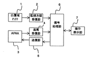
図15は、従来のビーム指向装置の概要を示すブロック図である。図において、1は目標の初期探知を行う広覆域アンテナ、2は広覆域アンテナ1で受信した信号から目標の周波数, パルス幅, パルス繰り返し周期等の目標電波諸元及び目標の方位を分析する監視方探受信部、3は目標信号を受信して送信部5からの種信号を増幅して相手電波発射源に電波を放射するとともに、放射を中断して受信も可能なAPAA、4はAPAAからの受信信号を解析して目標を追尾する追尾受信部、5は対抗目標に対抗するための送信種信号をAPAAに与える送信部、6は監視方探受信部2の受信結果から対抗する目標の有無を確認しそれが存在した場合はAPAAに切り換えて追尾受信及び送信を実施するよう指示を行う信号処理部で図示しないが対抗する目標の諸元の一覧表(対抗目標テーブル)を持っている。7は受信状況及び送信状況をオペレータに示し必要な場合オペレータが操作する操作表示部である。
【0004】
次に動作について説明する。
図16は、図15の従来のビーム指向装置の動作を示すフローチャートである。ステップS1で広覆域アンテナ1により信号を受信し、ステップS2で信号の有無の確認を行う。何も受信できなければステップS1へ戻るが、何らかの信号が受信された場合は、ステップS3で、監視方探受信部2により目標諸元及び目標方位の分析をおこない、ステップS4では信号処理部6で対抗目標テーブルとの比較を行って目標の有無を確認する。対抗目標テーブルと一致する目標がなければステップS1へ戻る。
対抗目標テーブルと一致する目標があった場合、これらのデータと方位情報とを用いて(これらを粗方探結果という)ステップS5のAPAA系に切り換えて受信し、ステップS6でまず受信信号の有無を確認し、確認出来なければ(目標を失探するという)ステップS7でアンテナのビーム指向方向の近辺を捜索受信して、それでも受信できなければステップS8でステップS1へ戻る。
ステップS6で受信が確認されるか、前述のステップS7の近辺捜索で受信できたときは、追尾受信部4で一致する目標を追尾(ステップS11)させるとともに、ステップS9で信号処理部6で規定した(あるいは操作表示部7で手動設定した)送信パラメータに従い送信部5で送信種信号を発生させて、APAA3により増幅して空中に放射する。ステップS9の送信開始後は、この送信の途中で時々受信に切り換えて追尾受信部4で目標の存在を確認するルックスルー受信(ステップS10)を行う。
【0005】
以上に説明した動作に於ける問題点の理解を助けるため、図17に広覆域アンテナ1の覆域Zと、広覆域アンテナ1による方位探知精度Z’と、APAA3のビーム幅Pを示す。110は目標である。
広覆域アンテナ1で広い覆域内Zを初期探知して、狭ビームPのAPAA系に移管する場合、APAA3は広覆域アンテナ1による方位探知精度Z’の幅の中に誘導される。このとき、Z’とPの関係が、例えば2Z’<Pの程度であれば問題はないが、方位探知精度Z’の幅が広ければ必ずしも目標110をAPAAで捕捉できるとは限らない。即ち、APAA3はビーム幅Pが狭いため、移管する前の広覆域アンテナ1による目標方位精度Z’がAPAA3のビーム幅Pより広ければ、目標を失探する恐れがある。
即ち、図17ではしばしば、Z>Z’>Pなる関係となっている。
しかし、広覆域アンテナ1の方位精度Z’の向上は広覆域性能と相反するため、広覆域性能を落とさないで方位精度を向上することは困難である。また、広覆域アンテナ1による目標探知は、アンテナ自身の利得が低いため、高感度化するのが難しく探知距離が短くなる。従って、目標方位精度を向上させる場合、装置の大型化やさらなる低感度化が生じてしまうことが懸念される。
【0006】
【発明が解決しようとする課題】
従来の狭ビーム指向装置は、以上のように構成されており、広覆域アンテナで広い覆域内を初期探知して目標を発見した後、狭ビームのAPAA系に移管する。しかし、APAAはビーム幅が狭いため、移管する前の広覆域アンテナによる目標方位精度がAPAAのビーム幅より広ければ目標を失探する恐れがある。
勿論、APAA系のビーム幅を広げることは意味がないし、また、広覆域アンテナの方探精度の向上は、アンテナ自身の利得が低いため、高感度化するのが難しく、探知距離が短くなるなどのため、装置の大型化やさらなる低感度化が懸念されて困難であり、結果としてAPAA系の狭ビーム性能を十分に活用することが出来ないという課題があった。
【0007】
この発明は、広覆域アンテナでの目標受信の後、APAA系に移管したとき、失探の恐れの少ないビーム指向装置を得ようとするものである。
【0008】
【課題を解決するための手段】
この発明による狭ビーム指向装置は、電波を発信した対抗目標の探知を行う広覆域アンテナ、
前記広覆域アンテナで受信した信号から前記電波の諸元及び前記目標の方位を分析して粗方探結果を出力する監視方探受信部、
前記監視方探受信部の分析結果と予め記憶した対抗目標のデータとを比較して目標の有無を確認し、前記目標を発見したとき目標認識信号を出力する信号処理部、
所定の方位探知精度を有するとともに、前記目標認識信号が出力されたとき前記広覆域アンテナの指向方向に指向する光学センサ、
前記光学センサの画像から前記目標を抽出して目標の方位を算出する画像処理部、
ビーム指向方向制御機能およびビーム幅制御機能を有するフェーズドアレイアンテナと、前記フェーズドアレイアンテナの受信信号を解析して目標を追尾する追尾受信部と、前記信号処理部の発信する前記目標認識信号を受けて前記分析結果にもとづき決定した電波諸元の送信信号を出力する送信部とを有し、前記目標の追尾と、前記送信信号の送出とを繰り返すアクティブフェーズドアレイアンテナ部とを備え、
前記アクティブフェーズドアレイアンテナ部の前記追尾受信部は、前記画像処理部が前記目標の方位を算出したときは算出された方位にもとづき前記追尾を開始し、前記画像処理部が前記目標を算出できないときは前記粗方探結果にもとづいて前記追尾を開始するものである。
【0009】
また、電波を発信した対抗目標の探知を行う広覆域アンテナ、
広覆域アンテナで受信した信号から電波の諸元及び目標の方位を分析する監視方探受信部、
監視方探受信部の分析結果と予め記憶した対抗目標のデータとを比較して、目標の有無を確認し、目標を発見したとき目標認識信号を出力する信号処理部、
広覆域アンテナの指向方向に指向し、所定の方位探知精度を有する光学センサ、
光学センサの画像から目標の可能性ある画像を抽出してその方位を算出する画像処理部、
画像処理部の算出した方位と信号処理部の確認した目標とから目標の方位を確定するデータ統合処理部、
ビーム指向方向制御機能およびビーム幅制御機能を有するフェーズドアレイアンテナと、フェーズドアレイアンテナの受信信号を解析して目標を追尾する追尾受信部と、信号処理部の発信する目標認識信号を受けて分析結果にもとづき決定した電波諸元の送信信号を出力する送信部とを有し、目標の追尾と、送信信号の送出とを繰り返すアクティブフェーズドアレイアンテナ部とを備え、
アクティブフェーズドアレイアンテナ部の追尾受信部は、データ統合処理部の処理した目標の方位にもとづき追尾を開始するものである。
【0010】
また、フェーズドアレイアンテナの追尾受信部が目標の信号を受信出来なかったとき、送信部は信号処理部の分析結果に基づく周波数よりも広帯域の周波数の電波を送信する失探処理を行うことにより、対抗目標に強電界の電波を放射し続けるものである。
【0011】
また、電波を発信した対抗目標の探知を行う広覆域アンテナ、
広覆域アンテナで受信した信号から電波の諸元及び目標の方位を分析する監視方探受信部、
監視方探受信部の分析結果と予め記憶した対抗目標のデータとを比較して、目標の有無を確認し、目標を発見したとき目標認識信号を出力する信号処理部、
広覆域アンテナの指向方向に指向し、広覆域アンテナと同等の視野角と所定の方位探知精度を有する光学センサ、
光学センサの画像と監視方探受信部の分析した方位とから目標を抽出して目標の方位を算出する画像処理部、
ビーム指向方向制御機能およびビーム幅制御機能を有するフェーズドアレイアンテナと、画像処理部の算出した目標の方位にもとづき追尾する光学系追尾部と、信号処理部の発信する目標認識信号を受けて分析結果にもとづき決定した電波諸元の送信信号を出力する送信部とを有し、目標を追尾しつつ送信信号を連続的に送出するアクティブフェーズドアレイアンテナ部とを備えたものである。
【0012】
また、光学センサは指向方向を制御する駆動制御部を備えるとともに、光学センサの視野角は広覆域アンテナの方位探知精度の1倍以上、2倍以下にしたものである。
【0013】
また、光学センサはその視野角が制御可能なものである。
【0014】
また、光学センサは2次元撮像素子を備えたものである。
【0015】
この発明による狭ビーム指向方法は、広覆域アンテナで受信した電波の諸元を解析してその方位を分析する監視方探手順と、
所定の方位探知精度を有する光学センサを広覆域アンテナの指向方向に指向し、光学センサの画像から目標を抽出してその方位を算出する画像処理手順と、
画像処理手順で得た目標の方位にフェーズドアレイアンテナを指向させた後、フェーズドアレイアンテナの受信信号にもとづきフェーズドアレイアンテナに目標を追尾させるとともに、フェーズドアレイアンテナから電波を放射するフェーズドアレイアンテナ系追尾送信手順とを含むものである。
【0016】
また、監視方探手順と画像処理手順とを同時に実施するものである。
【0017】
また、フェーズドアレイアンテナ系追尾送信手順において目標の信号を受信出来なかったとき、送信周波数の帯域幅をより広帯域に変化させて送信する失探処理手順を含むものである。
【0018】
また、広覆域アンテナで受信した電波の諸元を解析してその方位を分析する監視方探手順と、
所定の方位探知精度を有する光学センサを広覆域アンテナの指向方向に指向し、光学センサの画像から目標を抽出してその方位を算出するとともに、この画像により目標を追尾する画像追尾手順と、
画像追尾手順で得た目標の方位にフェーズドアレイアンテナを指向させた後、フェーズドアレイアンテナから電波を連続的に放射する連続送信手順とを含むものである。
【0019】
【発明の実施の形態】
実施の形態1.
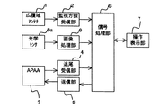
図1は、この発明の実施の形態1を示すブロック図である。図において、1は目標の初期探知を行う広覆域アンテナ、2は広覆域アンテナ1で受信した信号から目標の周波数, パルス幅, パルス繰り返し周期等の目標電波諸元及び目標の方位を分析する監視方探受信部、3は目標信号を受信して、送信部5からの種信号を増幅して空中に放射するアクティブフェーズドアレイアンテナ(以下APAA)でビーム指向方向制御機能とビーム幅制御機能とを備えている。
4はAPAAからの受信信号を解析して目標を追尾する追尾受信部、5は受信目標に対抗するための送信種信号をAPAAに与える送信部、6は監視方探受信部2の受信結果から対抗する目標の有無を確認しそれが存在した場合はAPAA3に切り換えて追尾受信及び送信を実施するよう指示を行う(目標認識信号と言う)信号処理部で図示しないが対抗する目標の諸元の一覧表(対抗目標テーブル)を持っている。7は受信状況及び送信状況をオペレータに示し必要な場合オペレータが操作する操作表示部である。なお、以下の説明でAPAA3と追尾受信部4と送信部5を含む部分をAPAA系またはアクティブフェーズドアレイアンテナ部と呼ぶ。
【0020】
8aは広覆域アンテナ1と同等の視野角とAPAA3の方位精度より高い方位探知精度を備えた光学センサで例えば2次元赤外線撮像素子を使用する。9は光学センサ8aから得られた画像から目標信号を抽出して目標の方位を算出する画像処理部である。
【0021】
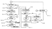
図2は、この発明の実施の形態1を示すフローチャートである。以下各フローチャート図において、ステップS1〜ステップS11は、従来の説明の図12で説明した同符号のステップと同じであるので詳細な説明は省略する。
光学センサ8aは歪曲の少ないレンズを使用すれば、視野角/素子数の角度分解能が得られ(ここで言う素子数は画像変換素子の素子数である)、これはその視野角の割りに極めて高精度の分解能である。従って、画素数の多い二次元撮像素子を使用すれば、視野角が広覆域アンテナ1と同等であっても、角度分解能を向上し、電波による方位探知よりも(広覆域アンテナ1は言うに及ばす、APAA3のビーム幅Pよりも)はるかに高い角度分解能が得られる。
【0022】
図2のステップS4において目標有りと判定したとき、ステップS21の光学系探知に切り換える。そしてステップS22で目標画像が捕らえられなければ、従来と同様に広覆域アンテナ1による粗方探結果を用いてAPAA系に移行する。また、目標画像が捕らえられたときはステップS23で目標方位を分析し、その結果(高精度方探結果という)を用いてAPAA系のステップS5に移行する。
図3は広覆域アンテナ1による覆域Zとその方位精度Z’、光学センサ8aによる覆域Aとその方位精度A’、APAA3による覆域Pとの関係を説明するための特性比較図である。
図に示すとおり
Z ≒A>Z’>A’ …(1)
A’≦P …(2)
となるように各装置の性能が決定されている。
式(1)ではAがほぼZに等しい程度とすることにより、失探の発生をより少なくしている。
【0023】
図2に於いて、ステップS3で目標の電波探知分析ができているにもかかわらずステップS22で目標を光学探知できない場合を想定しているが、これは光学探知の特性として、気象条件その他の外乱により、電波探知が可能でも光学探知が出来ない場合を想定したもので、光学探知系をAPAA系に移行する必須の方位確定手段としていない理由もここにある。
従来の装置では、監視方探受信結果である粗方探結果を基準として、APAA系を動作させていたが、本実施の形態では、粗方探結果を基準としてまず光学センサによる探知を行い。次に光学センサ系による高精度方探結果を入力してAPAA系に移管することで、APAA系移管時の失探を低減することができる。
【0024】
図2のステップS1〜S4は、この発明に言う監視方探手順である。
ステップS5はこの発明に言う追尾受信手順である。
ステップS21〜S23は、この発明に言う画像処理手順である。
ステップS5〜S11は、この発明に言うフェーズドアレイアンテナ系追尾送信手順である。
【0025】
実施の形態2.
図4は、この発明の実施の形態2を示すフローチャートである。実施の形態1と同じ目的、同じ効果を得る他の方法であるが、広覆域アンテナ系の処理(ステップS1〜ステップS4)と、光学センサ系の処理(ステップS21〜ステップS23)とを時間的に並列に行う(同時に実施する)ことにより、この発明の実施の形態1で説明した広覆域アンテナ系の処理後に光学センサ系の処理を実施する場合よりも処理時間が短縮されるという効果が得られる。
【0026】
ステップS31ではそれぞれに処理した結果をデータ統合処理してAPAA系に移管する。図に詳細は示さないが、ここでいうデータ統合処理とは、例えば光学系の高精度方探結果データがあればこれを用い、なければ広覆域アンテナ系の粗方探結果を用いるという意味であり、また、(光学系の視野角)≠(広覆域アンテナの覆域角)である場合に、粗方探結果を用いて光学系を誘導するなどの処理を含むものである。ステップS31はこの発明に言うデータ統合処理手順である。
【0027】
実施の形態3.
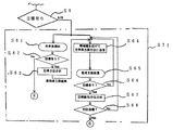
図5、図6は、この発明の実施の形態3を示すフローチャートである。この発明の実施の形態1では、APAA系で追尾受信中のルックスルーで目標を失探した場合、監視方探受信に戻らなければならない。これは方探を最初からやり直すということで時間がかかりすぎる。一方、APAA系で失探してしまう理由の多くは、対象目標が被探知、妨害回避を目的として例えば使用周波数その他の電波諸元を変更してしまったという理由が多いので、例えば、対抗目標が周波数を変化させた場合、図6に示すように広帯域周波数で送受信する失探処理を実施する。
【0028】
図5はステップS51の失探処理以外の部分は図2と同じなので詳細な説明を省略する。図6は図5のステップS51の失探処理の詳細を示すものである。図5のステップS8でNoであった場合、ステップS61〜ステップS63の光学系方探を実行するとともに(ステップS61は図2のステップS21、ステップS62はステップS22、ステップS63はステップS23とそれぞれ処理後の移行先は異なるものの同じ内容であるので説明は省略する)、ステップS64で光学センサ8aの方探結果で目標を追尾し、広帯域の送信を実施することにより、対抗目標レーダに強電界電波放射の効果を与え続けることができる。また、ステップS67で新たな目標諸元/方位分析結果を得れば旧データの更新を行うとともに本来のステップ(図5のステップS21)に戻る。
ステップS61〜62の光学系探知でも目標を見失った場合は本来のステップS1へ戻る。
図6のステップS61〜S68はこの発明に言う失探処理または失探処理手順である。
【0029】
実施の形態4.
図7、図8は、この発明の実施の形態4を示すフローチャートである。
本実施の形態は、実施の形態2の図4のフローに、実施の形態3で説明した図6の失探処理(ステップの移行先は無論異なっている)を実施することにより、失探した場合でも対抗目標レーダに効果を与え続けることができるようにしたものである。
図7の失探処理ステップS71は図8に詳細を示す。図8のステップS71の中のステップS61〜ステップS68は、図6の同符号のステップと下記の点を除いて同内容なので詳細な説明を省略する。即ち、光学探知のステップS62で目標を捕捉出来なかったときはステップS1の監視方探およびステップS21の光学方探の両方へ戻り、探知を最初からやり直す。また、ステップS68で、捕捉した目標が対抗目標であると判定されたときはステップS31のデータ統合処理にもどってデータを更新する。
【0030】
実施の形態5.
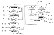
図9は、この発明の実施の形態5を示すフローチャートである。対抗目標が周波数変化等しないとわかっている単純なレーダの場合は、ステップS91〜ステップS94で目標方位の追尾を光学系センサで行う。ステップS95〜ステップS96でAPAAは光学系による目標方位情報を元に送信方位を修正しつつ連続的に送信(ときどき受信に切り替えて失探していないか確かめるルツクスルーを行わないという意味)することができるので、相手目標への送信を断絶させる必要がなく、効果をより高めることが出来る。
図9のステップS91〜S93はこの発明に言う画像追尾手順である。
ステップS94〜S96はこの発明に言う連続送信手順である。
【0031】
実施の形態6.
図10は、この発明の実施の形態6を示すフローチャートである。実施の形態5の監視方探受信(S1〜)と光学系探知(S21〜)とを並列に処理するもので、対抗目標が周波数変化等しないとわかっている単純なレーダの場合は、ステップS91〜ステップS94で目標方位の追尾を光学系センサで行う。ステップS95〜ステップS96でAPAAは光学系による目標方位情報を元に送信方位を修正しつつ常時送信(ルツクスルーなしという意味)することができるので、相手目標への送信を断絶させる必要がなく、効果をより高めることが出来る。
更に、加えて、目標を見失った後の処理が高速化されるという効果が得られる。
【0032】
実施の形態7.
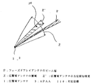
図11は、この発明の実施の形態7を示すブロック図である。また、図11の構成に於ける各センサの覆域(又は視野角)の相互の関係を図12に示す。即ち本実施の形態では、光学センサ8bの視野角Bは広覆域アンテナ1の覆域Zよりはるかに狭く、その方位精度Z’より若干広い程度(例えば1Z’以上で2Z’以下)の視野角とし、視野の移動は駆動制御部10で光学センサ8aの視軸を変化させる機構としている。
図12において、
Z>B≧Z’>B’ …(3)
B’≦P …(4)
(3)でBがZ’にほぼ等しい程度とすることによって、その光学センサの方位探知精度を高め、広覆域アンテナ系で探知した目標方位に光学センサを指向させたとき、詳細な方位を光学センサの画像データから得ることができる。
【0033】
実施の形態8.
図13は、この発明の実施の形態8を示すブロック図である。8cは視野角切換型(例えばズーミングのように連続的な変化を含む)の光学センサであり、その視野角は、初期探知では広視野角、光学系または広覆域アンテナ系の初期探知後は狭視野角に切り換えて、探知した目標方位に光学センサを指向させ、より詳細な方位を光学センサの画像データから得ることができる。図13の構成に於ける各センサの覆域(又は視野角)の相互の関係を図14に示す。
図14において、C(広)は光学センサ8cの広視野角を、C(狭)は光学センサ8cの狭視野角を示し、C’(広)、C’(狭)はそれぞれの方位探知精度を示している。
図に於いて、
Z ≧C(広)>C(狭)≧Z’>C’(広)>C’(狭) …(5)
C’(広)≦P …(6)
【0034】
【発明の効果】
以上のようにこの発明によれば、光学センサの高い方位探知精度を用いて狭ビーム指向装置のフェーズドアレイアンテナを制御しているので、フェーズドアレイアンテナへの移管時における失探の恐れを少なくすることができる。
【0035】
また、光学センサによる方探と広覆域アンテナによる方探とを並列に実施しているので、方探時間をより短縮できる。
【0036】
また、フェーズドアレイアンテナが失探したとき、より広帯域の電波を放射するので、失探中も対抗目標に影響を与えつづけることができる。
【0037】
また、光学センサによる追尾を行い、この光学センサの方位探知データにもとづきフェーズドアレイアンテナの指向制御を行うことにより、連続的に電波放射を行うことができ、対抗目標により大きな効果を与えることができる。
【0038】
また、光学センサは広覆域アンテナの方位探知精度より広く、その覆域より狭い視野角と、指向方向の駆動制御部とを備えているので、光学センサによる方位探知精度をより高めることができる。
【0039】
また、光学センサの視野角は可変なので、必要時に必要な方位探知精度を得ることができ、目標を失探する恐れをより少なくすることができる。
【0040】
また、光学センサとして2次元撮像素子を用いているので容易に方位探知精度を高めることができる。
【0041】
この発明による狭ビーム指向方法によれば、画像処理手順により目標の方向にフェーズドアレイアンテナを指向させたのち、フェーズドアレイアンテナの受信により目標を追尾しているので、広覆域アンテナからフェーズドアレイアンテナに移管したとき失探する恐れが少ない。
【0042】
また、広覆域アンテナによる探知と光学センサによる探知とを同時刻に実施するので探知時間を短縮できる。
【0043】
また、目標の信号を受信できなかったとき、送信周波数の帯域幅をより広帯域に変化させて送信する失探処理手順を含むので、失探の可能性をより低減することができる。
【0044】
また、画像追尾手順によってフェーズドアレイアンテナを指向させた後、フェーズドアレイアンテナから電波を連続的に放射する連続送信手順を含むので、失探中にも対抗目標に効果を与え続けることができる。
【図面の簡単な説明】
【図1】 この発明の実施の形態1による狭ビーム指向装置の構成を示すブロック図である。
【図2】 図1の狭ビーム指向装置の動作を示すフローチャートである。
【図3】 図1の狭ビーム指向装置の動作を説明するための各センサの性能比較説明図である。
【図4】 この発明の実施の形態2による狭ビーム指向装置の動作を示すフローチャートである。
【図5】 この発明の実施の形態3による狭ビーム指向装置の動作を示すフローチャートである。
【図6】 図5のフローチャートの部分を詳細に示すフローチャートである。
【図7】 この発明の実施の形態4による狭ビーム指向装置の動作を示すフローチャートである。
【図8】 図7のフローチャートの部分を詳細に示すフローチャートである。
【図9】 この発明の実施の形態5による狭ビーム指向装置の動作を示すフローチャートである。
【図10】 この発明の実施の形態6による狭ビーム指向装置の動作を示すフローチャートである。
【図11】 この発明の実施の形態7による狭ビーム指向装置の構成を示すブロック図である。
【図12】 図11の狭ビーム指向装置の特性を示す特性比較図である。
【図13】 この発明の実施の形態8による狭ビーム指向装置を示すブロック図である。
【図14】 図13の狭ビーム指向装置の特性を示す特性比較図である。
【図15】 従来の狭ビーム指向装置を示すブロック図である。
【図16】 図15の狭ビーム指向装置の動作を示すフローチャートである。
【図17】 図15の狭ビーム指向装置の特性を示す特性図である。
【符号の説明】
1 広覆域アンテナ、 2 監視方探受信部、
3 アクティブフェーズドアレイアンテナ、 4 追尾受信部、
5 送信部、 6 信号処理部、 7 操作表示部、 8a 光学センサ、
8b 光学センサ、 8c 光学センサ、 9 画像処理部、
10 駆動制御部、
A 光学センサ8aの視野角、 A’ 光学センサ8aの方位探知精度、
B 光学センサ8bの視野角、 B’ 光学センサ8bの方位探知精度、
C 光学センサ8cの視野角、 C’ 光学センサ8cの方位探知精度、
P フェーズドアレイアンテナのビーム角、
Z 広覆域アンテナの覆域、 Z’ 広覆域アンテナの方位探知精度。[0001]
BACKGROUND OF THE INVENTION
The present invention relates to an improvement in pointing accuracy of a narrow beam pointing device using an active phased array antenna (APAA).
[0002]
[Prior art]
A phased array antenna that controls the directivity characteristics of the entire antenna by adjusting the excitation power and excitation phase of each of a number of element antennas arranged according to a certain rule is controlled in real time according to the target size, moving speed, etc. By performing (active phased array antenna, hereinafter referred to as APAA), excellent directivity control performance and narrow beam performance that cannot be obtained by a conventional antenna system can be obtained.
By utilizing such characteristics, a strong radio wave is radiated to the target radar device as a target, and the receiving circuit of the opponent radar is saturated, so that it can be used as a device that affects the opponent radar.
The APAA beam can have a very narrow angle, and its gain can be increased. On the other hand, it is difficult to keep capturing the target, and various devices are required for tracking the counter target.
Hereinafter, a beam directing device that detects a radio wave emission source and emits a strong beam to the emission source will be described as an example.
[0003]
FIG. 15 is a block diagram showing an outline of a conventional beam directing device. In the figure, 1 is a wide coverage antenna that performs initial detection of a target, 2 is analysis of target radio wave parameters such as target frequency, pulse width, pulse repetition period, and target direction from signals received by the
[0004]
Next, the operation will be described.
FIG. 16 is a flowchart showing the operation of the conventional beam directing device of FIG. A signal is received by the
If there is a target that coincides with the counter target table, the received data is switched to the APAA system in step S5 using these data and azimuth information (referred to as rough search results), and first, in step S6, the presence or absence of a received signal If it cannot be confirmed (the target is lost), the vicinity of the antenna in the beam directing direction is searched for and received in step S7, and if it cannot be received, the process returns to step S1 in step S8.
When reception is confirmed in step S6 or reception is possible in the vicinity search of step S7 described above, the
[0005]
In order to help understanding of the problems in the operation described above, FIG. 17 shows the coverage Z of the
When the wide
That is, in FIG. 17, there is often a relationship of Z> Z ′> P.
However, since the improvement in the azimuth accuracy Z ′ of the
[0006]
[Problems to be solved by the invention]
The conventional narrow beam directing device is configured as described above, and after initial detection of a wide coverage area with a wide coverage antenna to find a target, it is transferred to a narrow beam APAA system. However, since the beam width of APAA is narrow, if the target azimuth accuracy by the wide coverage antenna before transfer is wider than the beam width of APAA, the target may be missed.
Of course, it is meaningless to widen the beam width of the APAA system, and the improvement in the direction finding accuracy of the wide coverage antenna is difficult to increase the sensitivity because the gain of the antenna itself is low, and the detection distance is shortened. For this reason, there has been a problem that it is difficult to increase the size of the apparatus and to further reduce the sensitivity, and as a result, the narrow beam performance of the APAA system cannot be fully utilized.
[0007]
The present invention seeks to obtain a beam directing device that is less likely to be missed when transferred to an APAA system after target reception by a wide coverage antenna.
[0008]
[Means for Solving the Problems]
A narrow beam pointing device according to the present invention includes a wide coverage antenna that detects a counter target that has transmitted radio waves,
Analyzing the specifications of the radio wave and the orientation of the target from the signal received by the wide coverage antennaTo output the rough search resultsMonitoring method receiver,
A signal processing unit that compares the analysis result of the monitoring method search reception unit with the prestored counter target data to check the presence or absence of a target, and outputs a target recognition signal when the target is found,
When the target recognition signal is output while having a predetermined direction detection accuracyDirected in the direction of the wide coverage antennaDoOptical sensors,
Of the optical sensorFrom the imageAn image processing unit for extracting the target and calculating a direction of the target;
Receiving a phased array antenna having a beam pointing direction control function and a beam width control function, a tracking receiving unit for analyzing a received signal of the phased array antenna and tracking a target, and receiving the target recognition signal transmitted by the signal processing unit. A transmission unit that outputs a transmission signal of radio wave specifications determined based on the analysis result, and includes an active phased array antenna unit that repeats the tracking of the target and the transmission of the transmission signal,
The tracking receiving unit of the active phased array antenna unit isWhen the image processing unit calculates the target azimuth, the tracking is started based on the calculated azimuth. When the image processing unit cannot calculate the target, the tracking is performed based on the rough search result. StartIs.
[0009]
In addition, a wide coverage antenna that detects the opposing target that sent the radio wave,
A monitoring probe receiver that analyzes the radio wave specifications and target orientation from the signal received by the wide coverage antenna,
A signal processing unit that compares the analysis result of the monitoring method search receiving unit and the data of the counter target stored in advance, checks the presence of the target, and outputs a target recognition signal when the target is found,
An optical sensor that is directed in the direction of the wide coverage antenna and has a predetermined azimuth detection accuracy,
An image processing unit that extracts an image of a possible target from an image of an optical sensor and calculates its orientation;
A data integration processing unit for determining a target orientation from the calculated orientation of the image processing unit and the target confirmed by the signal processing unit;
Phased array antenna having beam directing direction control function and beam width control function, tracking receiving unit for analyzing the received signal of the phased array antenna to track the target, and target recognition signal transmitted by the signal processing unit A transmission unit that outputs a transmission signal of radio wave specifications determined based on the active phased array antenna unit that repeats target tracking and transmission of the transmission signal,
The tracking receiving unit of the active phased array antenna unit starts tracking based on the target direction processed by the data integration processing unit.
[0010]
In addition, when the tracking reception unit of the phased array antenna fails to receive the target signal, the transmission unit performs a missed search process of transmitting a radio wave having a frequency wider than the frequency based on the analysis result of the signal processing unit, It continues to radiate strong electric fields to the opposing target.
[0011]
In addition, a wide coverage antenna that detects the opposing target that sent the radio wave,
A monitoring probe receiver that analyzes the radio wave specifications and target orientation from the signal received by the wide coverage antenna,
A signal processing unit that compares the analysis result of the monitoring method search receiving unit and the data of the counter target stored in advance, checks the presence of the target, and outputs a target recognition signal when the target is found,
An optical sensor that is oriented in the direction of the wide coverage antenna and has a viewing angle equivalent to the wide coverage antenna and a predetermined azimuth detection accuracy,
An image processing unit for extracting a target from the image of the optical sensor and the azimuth analyzed by the monitoring method receiver and calculating the azimuth of the target;
Analysis results upon receiving a phased array antenna having a beam pointing direction control function and a beam width control function, an optical system tracking unit for tracking based on the target orientation calculated by the image processing unit, and a target recognition signal transmitted by the signal processing unit And an active phased array antenna unit for continuously transmitting the transmission signal while tracking the target.
[0012]
In addition, the optical sensor includes a drive control unit that controls the directivity direction, and the viewing angle of the optical sensor is set to be 1 to 2 times the orientation detection accuracy of the wide coverage antenna.
[0013]
The optical sensor can control the viewing angle.
[0014]
The optical sensor includes a two-dimensional image sensor.
[0015]
A narrow beam directing method according to the present invention comprises a monitoring method for analyzing the direction of a radio wave received by a wide coverage antenna and analyzing its orientation;
An image processing procedure for directing an optical sensor having a predetermined azimuth detection accuracy in the directional direction of the wide coverage antenna, extracting a target from the image of the optical sensor, and calculating its azimuth;
After directing the phased array antenna to the target orientation obtained by the image processing procedure, the phased array antenna tracks the target based on the received signal of the phased array antenna and radiates radio waves from the phased array antenna. A transmission procedure.
[0016]
In addition, the monitoring method searching procedure and the image processing procedure are performed simultaneously.
[0017]
Further, it includes a missed processing procedure in which when the target signal cannot be received in the phased array antenna tracking transmission procedure, the transmission frequency bandwidth is changed to a wider bandwidth and transmitted.
[0018]
In addition, the monitoring method to analyze the direction of the radio wave received by the wide coverage antenna and analyze the direction,
An image tracking procedure for directing an optical sensor having a predetermined azimuth detection accuracy in the directional direction of the wide coverage antenna, extracting a target from the image of the optical sensor and calculating its azimuth, and tracking the target with this image;
And a continuous transmission procedure of continuously radiating radio waves from the phased array antenna after directing the phased array antenna to the target orientation obtained by the image tracking procedure.
[0019]
DETAILED DESCRIPTION OF THE INVENTION
FIG. 1 is a block
4 is a tracking receiving unit that analyzes a received signal from APAA and tracks a target, 5 is a transmitting unit that gives a transmission type signal to APAA to counter the receiving target, and 6 is a reception result of the monitoring
[0020]
8a is an optical sensor having a viewing angle equivalent to that of the
[0021]
FIG. 2 is a flowchart showing the first embodiment of the present invention. In the flowcharts shown below, steps S1 to S11 are the same as the steps with the same reference numerals described in FIG.
If a lens with little distortion is used for the optical sensor 8a, the angle resolution of the viewing angle / number of elements can be obtained (the number of elements here is the number of elements of the image conversion element), which is extremely high for the viewing angle. High resolution. Therefore, if a two-dimensional imaging device with a large number of pixels is used, even if the viewing angle is the same as that of the
[0022]
When it is determined in step S4 in FIG. 2 that there is a target, the optical system detection is switched to step S21. If the target image is not captured in step S22, the process proceeds to the APAA system using the result of the rough search by the
FIG. 3 is a characteristic comparison diagram for explaining the relationship between the coverage Z by the
As shown in the figure
Z≈A> Z ′> A ′ (1)
A ′ ≦ P (2)
The performance of each device is determined so that
In the formula (1), the occurrence of missed search is reduced by setting A to be approximately equal to Z.
[0023]
In FIG. 2, it is assumed that the target cannot be optically detected in step S22 even though the target radio wave detection analysis has been performed in step S3. This is based on the assumption that radio detection is possible due to disturbance, but optical detection is not possible. This is also why the optical detection system is not an indispensable direction determining means for shifting to the APAA system.
In the conventional apparatus, the APAA system is operated on the basis of the coarse search result that is the reception result of the monitoring method search. In the present embodiment, detection is first performed by the optical sensor on the basis of the coarse search result. Next, by inputting a high-accuracy direction search result by the optical sensor system and transferring it to the APAA system, it is possible to reduce the lost search during the APAA system transfer.
[0024]
Steps S1 to S4 in FIG. 2 are monitoring method search procedures according to the present invention.
Step S5 is a tracking reception procedure according to the present invention.
Steps S21 to S23 are image processing procedures according to the present invention.
Steps S5 to S11 are the phased array antenna system tracking transmission procedure according to the present invention.
[0025]
FIG. 4 is a flowchart showing the second embodiment of the present invention. Although it is another method for obtaining the same object and the same effect as in the first embodiment, the processing of the wide coverage antenna system (steps S1 to S4) and the processing of the optical sensor system (steps S21 to S23) are timed. By performing in parallel (simultaneously), the processing time is shortened compared to the case where the processing of the optical sensor system is performed after the processing of the wide coverage antenna system described in the first embodiment of the present invention. Is obtained.
[0026]
In step S31, the result of each processing is subjected to data integration processing and transferred to the APAA system. Although details are not shown in the figure, the data integration processing here means that, for example, if there is high-precision direction search result data of the optical system, this is used, and if not, the rough search result of the wide coverage antenna system is used. In addition, when (the viewing angle of the optical system) ≠ (the coverage angle of the wide coverage antenna), processing including guiding the optical system using the coarse search result is included.Step S31 is a data integration processing procedure according to the present invention.
[0027]
5 and 6 are
[0028]
Since FIG. 5 is the same as FIG. 2 except for the missed search process in step S51, detailed description thereof is omitted. FIG. 6 shows details of the missed search process in step S51 of FIG. If No in step S8 in FIG. 5, the optical system search in steps S61 to S63 is executed (step S61 is processed in step S21 in FIG. 2, step S62 is in step S22, and step S63 is processed in step S23. The subsequent destinations are different but have the same contents, so the explanation is omitted.) In step S64, the target is tracked by the direction finding result of the optical sensor 8a, and broadband transmission is performed. Can continue to give radiation effects. If a new target specification / orientation analysis result is obtained in step S67, the old data is updated and the process returns to the original step (step S21 in FIG. 5).
If the target is lost in the optical system detection in steps S61 to S62, the process returns to the original step S1.
Steps S61 to S68 in FIG. 6 are a lost search process or a lost search process procedure according to the present invention.
[0029]
7 and 8 are
In the present embodiment, the flow of FIG. 4 of the second embodiment is searched for by performing the lost search process of FIG. 6 described in the third embodiment (the destination of step transition is of course different). Even in this case, it is possible to continue to give an effect to the opposing target radar.
FIG. 8 shows details of the lost-lookup processing step S71 of FIG. Steps S61 to S68 in step S71 in FIG. 8 have the same contents as the steps with the same reference numerals in FIG. That is, when the target cannot be captured in step S62 of the optical detection, the process returns to both the monitoring method search in step S1 and the optical direction search in step S21, and the detection is restarted from the beginning. If it is determined in step S68 that the captured target is a counter target, the data is returned to the data integration process in step S31 to update the data.
[0030]
FIG. 9 is a flowchart showing the fifth embodiment of the present invention. In the case of a simple radar whose counter target is known not to change in frequency or the like, the target direction is tracked by the optical system sensor in steps S91 to S94. In steps S95 to S96, the APAA can continuously transmit the transmission direction while correcting the transmission direction based on the target direction information by the optical system (meaning that it does not perform a look-through to check whether it is lost by switching to reception occasionally). Therefore, it is not necessary to cut off transmission to the opponent target, and the effect can be further enhanced.
Steps S91 to S93 in FIG. 9 are image tracking procedures according to the present invention.
Steps S94 to S96 are a continuous transmission procedure according to the present invention.
[0031]
FIG. 10 is a flowchart showing the sixth embodiment of the present invention. In the case of a simple radar in which the monitoring method detection reception (S1) and the optical system detection (S21 to S) in the fifth embodiment are processed in parallel and the counter target is known not to change in frequency or the like, step S91 is performed. In step S94, the target azimuth is tracked by the optical system sensor. In step S95 to step S96, the APAA can always transmit (meaning that there is no look-through) while correcting the transmission direction based on the target direction information by the optical system, so there is no need to disconnect the transmission to the partner target. Can be further increased.
In addition, the effect of speeding up the processing after losing the target is obtained.
[0032]
FIG. 11 is a block
In FIG.
Z> B ≧ Z ′> B ′ (3)
B ′ ≦ P (4)
By making B approximately equal to Z ′ in (3), the azimuth detection accuracy of the optical sensor is improved, and when the optical sensor is directed to the target azimuth detected by the wide coverage antenna system, a detailed azimuth is obtained. It can be obtained from the image data of the optical sensor.
[0033]
FIG. 13 is a block diagram showing an eighth embodiment of the present invention. 8c is an optical sensor of a viewing angle switching type (for example, including a continuous change like zooming). The viewing angle is a wide viewing angle in the initial detection, and after the initial detection of the optical system or the wide coverage antenna system. By switching to a narrow viewing angle, the optical sensor can be directed to the detected target orientation, and a more detailed orientation can be obtained from the image data of the optical sensor. FIG. 14 shows the relationship between the coverage areas (or viewing angles) of the sensors in the configuration of FIG.
In FIG. 14, C (wide) indicates the wide viewing angle of the optical sensor 8c, C (narrow) indicates the narrow viewing angle of the optical sensor 8c, and C ′ (wide) and C ′ (narrow) indicate the respective direction detection accuracy. Is shown.
In the figure,
Z ≧ C (wide)> C (narrow) ≧ Z ′> C ′ (wide)> C ′ (narrow) (5)
C ′ (wide) ≦ P (6)
[0034]
【The invention's effect】
As described above, according to the present invention, the phased array antenna of the narrow beam directing device is controlled by using the high azimuth detection accuracy of the optical sensor, so that the risk of missing detection at the time of transfer to the phased array antenna is reduced. be able to.
[0035]
Further, since the direction search by the optical sensor and the direction search by the wide coverage antenna are performed in parallel, the direction search time can be further shortened.
[0036]
In addition, when the phased array antenna is lost, a broader band of radio waves is radiated, so that it is possible to continue to influence the counter target even during a lost search.
[0037]
In addition, by tracking with an optical sensor and controlling the orientation of the phased array antenna based on the direction detection data of this optical sensor, radio wave radiation can be continuously performed, and a great effect can be given to the opposing target. .
[0038]
Further, the optical sensor has a wider viewing angle than the wide coverage antenna and a narrower viewing angle than that of the coverage area and a drive control unit in the pointing direction, so that the orientation detection accuracy by the optical sensor can be further increased. .
[0039]
Further, since the viewing angle of the optical sensor is variable, the necessary direction finding accuracy can be obtained when necessary, and the possibility of missing the target can be reduced.
[0040]
In addition, since the two-dimensional image sensor is used as the optical sensor, the direction finding accuracy can be easily increased.
[0041]
According to the narrow beam directing method of the present invention, the phased array antenna is directed in the target direction by the image processing procedure, and then the target is tracked by reception of the phased array antenna. There is little risk of missing when transferred to.
[0042]
In addition, since the detection by the wide coverage antenna and the detection by the optical sensor are performed at the same time, the detection time can be shortened.
[0043]
In addition, since it includes a missed search procedure in which the bandwidth of the transmission frequency is changed to a wider bandwidth when the target signal cannot be received, the possibility of missed search can be further reduced.
[0044]
In addition, since the phased array antenna is directed by the image tracking procedure and then includes a continuous transmission procedure in which radio waves are continuously radiated from the phased array antenna, it is possible to continue to exert an effect on the counter target even during a missed search.
[Brief description of the drawings]
FIG. 1 is a block diagram showing a configuration of a narrow beam directing device according to
FIG. 2 is a flowchart showing the operation of the narrow beam directing device of FIG.
FIG. 3 is a performance comparison explanatory diagram of each sensor for explaining the operation of the narrow beam directing device of FIG. 1;
FIG. 4 is a flowchart showing an operation of the narrow beam directing device according to the second embodiment of the present invention.
FIG. 5 is a flowchart showing an operation of the narrow beam directing device according to the third embodiment of the present invention.
6 is a flowchart showing in detail a part of the flowchart of FIG.
FIG. 7 is a flowchart showing an operation of the narrow beam directing device according to the fourth embodiment of the present invention.
FIG. 8 is a flowchart showing in detail a part of the flowchart of FIG. 7;
FIG. 9 is a flowchart showing an operation of the narrow beam directing device according to the fifth embodiment of the present invention.
FIG. 10 is a flowchart showing an operation of the narrow beam directing device according to the sixth embodiment of the present invention.
FIG. 11 is a block diagram showing a configuration of a narrow beam directing device according to
12 is a characteristic comparison diagram showing characteristics of the narrow beam directing device of FIG. 11. FIG.
FIG. 13 is a block diagram showing a narrow beam directing device according to an eighth embodiment of the present invention.
14 is a characteristic comparison diagram showing characteristics of the narrow beam directing device of FIG. 13; FIG.
FIG. 15 is a block diagram showing a conventional narrow beam directing device.
16 is a flowchart showing the operation of the narrow beam directing device of FIG.
FIG. 17 is a characteristic diagram showing characteristics of the narrow beam directing device of FIG. 15;
[Explanation of symbols]
1 Wide coverage antenna, 2 Monitoring method receiver,
3 active phased array antenna, 4 tracking receiver,
5 Transmitter, 6 Signal Processor, 7 Operation Display, 8a Optical Sensor,
8b optical sensor, 8c optical sensor, 9 image processing unit,
10 Drive controller,
A viewing angle of the optical sensor 8a, A ′ orientation detection accuracy of the optical sensor 8a,
B viewing angle of the
C viewing angle of the optical sensor 8c, C ′ orientation detection accuracy of the optical sensor 8c,
Beam angle of P phased array antenna,
Z Coverage of wide coverage antenna, Z 'Wide-range coverage direction detection accuracy.
Claims (10)
前記広覆域アンテナで受信した信号から前記電波の諸元及び前記目標の方位を分析して粗方探結果を出力する監視方探受信部、
前記監視方探受信部の分析結果と予め記憶した対抗目標のデータとを比較して目標の有無を確認し、前記目標を発見したとき目標認識信号を出力する信号処理部、
所定の方位探知精度を有するとともに、前記目標認識信号が出力されたとき前記広覆域アンテナの指向方向に指向する光学センサ、
前記光学センサの画像から前記目標を抽出して目標の方位を算出する画像処理部、
ビーム指向方向制御機能およびビーム幅制御機能を有するフェーズドアレイアンテナと、前記フェーズドアレイアンテナの受信信号を解析して目標を追尾する追尾受信部と、前記信号処理部の発信する前記目標認識信号を受けて前記分析結果にもとづき決定した電波諸元の送信信号を出力する送信部とを有し、前記目標の追尾と、前記送信信号の送出とを繰り返すアクティブフェーズドアレイアンテナ部とを備え、
前記アクティブフェーズドアレイアンテナ部の前記追尾受信部は、前記画像処理部が前記目標の方位を算出したときは算出された方位にもとづき前記追尾を開始し、前記画像処理部が前記目標を算出できないときは前記粗方探結果にもとづいて前記追尾を開始することを特徴とした狭ビーム指向装置。Wide coverage antenna that detects the opposing target that sent the radio wave,
A monitoring probe receiving unit that analyzes the specifications of the radio wave and the direction of the target from the signal received by the wide coverage antenna, and outputs a rough probe result ;
A signal processing unit that compares the analysis result of the monitoring method search reception unit with the prestored counter target data to check the presence or absence of a target, and outputs a target recognition signal when the target is found,
An optical sensor having a predetermined azimuth detection accuracy and pointing in a pointing direction of the wide coverage antenna when the target recognition signal is output ;
An image processing unit for extracting the target from the image of the optical sensor and calculating a direction of the target;
Receiving a phased array antenna having a beam pointing direction control function and a beam width control function, a tracking receiving unit for analyzing a received signal of the phased array antenna and tracking a target, and receiving the target recognition signal transmitted by the signal processing unit. A transmission unit that outputs a transmission signal of radio wave specifications determined based on the analysis result, and includes an active phased array antenna unit that repeats the tracking of the target and the transmission of the transmission signal,
The tracking reception unit of the active phased array antenna unit starts the tracking based on the calculated direction when the image processing unit calculates the target direction, and the image processing unit cannot calculate the target Is a narrow beam pointing device characterized in that the tracking is started based on the result of the rough search .
前記広覆域アンテナで受信した信号から前記電波の諸元及び前記目標の方位を分析する監視方探受信部、
前記監視方探受信部の分析結果と予め記憶した対抗目標のデータとを比較して目標の有無を確認し、前記目標を発見したとき目標認識信号を出力する信号処理部、
前記広覆域アンテナの指向方向に指向し、所定の方位探知精度を有する光学センサ、
前記光学センサの画像から前記目標の可能性ある画像を抽出してその方位を算出する画像処理部、
前記画像処理部の算出した方位と前記信号処理部の確認した目標とから前記目標の方位を確定するデータ統合処理部、
ビーム指向方向制御機能およびビーム幅制御機能を有するフェーズドアレイアンテナと、前記データ統合処理部の処理した前記目標の方位にもとづき追尾を開始し、前記フェーズドアレイアンテナの受信信号を解析して目標を追尾する追尾受信部と、前記信号処理部の発信する前記目標認識信号を受けて前記分析結果にもとづき決定した電波諸元の送信信号を出力するとともに、前記追尾受信部が目標の信号を受信出来なかったとき、前記信号処理部の分析結果に基づく周波数よりも広帯域の周波数の電波を送信する失探処理を行うことにより、前記対抗目標に強電界の電波を放射し続ける送信部とを有し、前記目標の追尾と、前記送信信号の送出とを繰り返すアクティブフェーズドアレイアンテナ部とを備えたことを特徴とする狭ビーム指向装置。Wide coverage antenna that detects the opposing target that sent the radio wave,
A monitoring probe receiving unit for analyzing the specifications of the radio wave and the direction of the target from the signal received by the wide coverage antenna;
A signal processing unit that compares the analysis result of the monitoring method search reception unit with the prestored counter target data to check the presence or absence of a target, and outputs a target recognition signal when the target is found,
An optical sensor oriented in the direction of the wide coverage antenna and having a predetermined azimuth detection accuracy;
An image processor that extracts an image of the target from the image of the optical sensor and calculates its orientation;
A data integration processing unit for determining the direction of the target from the direction calculated by the image processing unit and the target confirmed by the signal processing unit;
The tracking is started based on the phased array antenna having the beam directing direction control function and the beam width control function, and the target direction processed by the data integration processing unit, and the target is tracked by analyzing the received signal of the phased array antenna. And receiving the target recognition signal transmitted by the signal processing unit and outputting a transmission signal of radio wave specifications determined based on the analysis result, and the tracking receiving unit cannot receive the target signal A transmission unit that continuously emits radio waves of a strong electric field to the opposing target by performing a missed search process of transmitting radio waves of a frequency wider than the frequency based on the analysis result of the signal processing unit , A narrow beam finger comprising an active phased array antenna unit that repeats the tracking of the target and the transmission of the transmission signal Apparatus.
前記広覆域アンテナで受信した信号から前記電波の諸元及び前記目標の方位を分析する監視方探受信部、
前記監視方探受信部の分析結果と予め記憶した対抗目標のデータとを比較して目標の有無を確認し、前記目標を発見したとき目標認識信号を出力する信号処理部、
前記広覆域アンテナと同等の視野角と所定の方位探知精度を有し、前記監視方探受信部の分析した目標の方位に指向する光学センサ、
前記光学センサの画像から前記目標を抽出して目標の方位を算出する画像処理部、
ビーム指向方向制御機能およびビーム幅制御機能を有するフェーズドアレイアンテナと、前記画像処理部の算出した前記目標の方位にもとづき追尾する光学系追尾部と、前記信号処理部の発信する前記目標認識信号を受けて前記分析結果にもとづき決定した電波諸元の送信信号を出力する送信部とを有し、前記目標を追尾しつつ前記送信信号を連続的に送出するアクティブフェーズドアレイアンテナ部とを備えたことを特徴とする狭ビーム指向装置。Wide coverage antenna that detects the opposing target that sent the radio wave,
A monitoring probe receiving unit for analyzing the specifications of the radio wave and the direction of the target from the signal received by the wide coverage antenna;
A signal processing unit that compares the analysis result of the monitoring method search reception unit with the prestored counter target data to check the presence or absence of a target, and outputs a target recognition signal when the target is found,
The has a wide covering area antenna equivalent viewing angle and a predetermined azimuth detection accuracy, the optical sensor oriented in the orientation of the target of analysis of the monitoring side probe receiver unit,
An image processing unit for extracting the target from the image of the optical sensor and calculating a direction of the target;
A phased array antenna having a beam directing direction control function and a beam width control function, an optical system tracking unit for tracking based on the target orientation calculated by the image processing unit, and the target recognition signal transmitted by the signal processing unit. And a transmission unit that outputs a transmission signal of radio wave specifications determined based on the analysis result, and an active phased array antenna unit that continuously transmits the transmission signal while tracking the target Narrow beam pointing device characterized by.
所定の方位探知精度を有する光学センサを前記広覆域アンテナの指向方向に指向し、前記光学センサの画像から目標を抽出してその方位を算出する画像処理手順と、
前記画像処理手順で前記目標の方位が得られたときは前記フェーズドアレイアンテナを得られた目標の方位に指向させ、前記画像処理手順により前記目標の方位が算出できなかったときは前記粗方探結果にもとづいて前記フェーズドアレイアンテナを指向させた後、前記フェーズドアレイアンテナの受信信号にもとづき前記フェーズドアレイアンテナに前記目標を追尾させ前記フェーズドアレイアンテナから電波を放射するフェーズドアレイアンテナ系追尾送信手順とを含むことを特徴とする狭ビーム指向方法。 A monitoring method that analyzes the specifications of the radio wave received by the wide coverage antenna, analyzes its direction, and outputs the result of rough search ,
An image processing procedure for directing an optical sensor having a predetermined azimuth detection accuracy in the directional direction of the wide coverage antenna, extracting a target from the image of the optical sensor, and calculating the azimuth;
When the target azimuth is obtained by the image processing procedure , the phased array antenna is directed to the obtained target azimuth, and when the target azimuth cannot be calculated by the image processing procedure, the coarse search is performed. A phased array antenna system tracking transmission procedure for directing the phased array antenna based on a result and then tracking the target to the phased array antenna based on a received signal of the phased array antenna and radiating a radio wave from the phased array antenna; A narrow beam directing method comprising:
所定の方位探知精度を有する光学センサを前記広覆域アンテナの指向方向に指向し、前記光学センサの画像から目標を抽出してその方位を算出する画像処理手順と、
前記画像処理手順で算出した方位と前記監視方探手順で得た目標とから前記目標の方位を確定するデータ統合処理手順と、
前記データ統合処理手順で得た前記目標の方位にもとづき追尾を開始し、前記受信信号を解析して目標を追尾する追尾受信手順と、前記追尾受信手順で目標の信号を受信出来なかったとき、前記監視方探手順の結果に基づく前記電波諸元の周波数よりも広帯域の周波数の電波を送信する失探処理を行うことにより、前記対抗目標に強電界の電波を放射し続ける連続送信手順とを含むことを特徴とする狭ビーム指向方法。A monitoring method that analyzes the specifications of the radio wave received by the wide coverage antenna and confirms the presence or absence of the target by comparing it with the data of the pre-stored counter target, and analyzes its orientation,
An image processing procedure for directing an optical sensor having a predetermined azimuth detection accuracy in the directional direction of the wide coverage antenna, extracting a target from the image of the optical sensor, and calculating the azimuth;
A data integration processing procedure for determining the orientation of the target from the orientation calculated in the image processing procedure and the target obtained in the monitoring method;
When tracking is started based on the direction of the target obtained in the data integration processing procedure, the reception signal is analyzed to track the target, and the target signal is not received in the tracking reception procedure, A continuous transmission procedure for continuously radiating a radio wave of a strong electric field to the opposing target by performing a missed search process for transmitting a radio wave having a frequency wider than the frequency of the radio wave specifications based on the result of the monitoring method search procedure. A narrow beam directing method comprising:
Priority Applications (1)
| Application Number | Priority Date | Filing Date | Title |
|---|---|---|---|
| JP2001009804A JP3697397B2 (en) | 2001-01-18 | 2001-01-18 | Narrow beam pointing device and narrow beam pointing method |
Applications Claiming Priority (1)
| Application Number | Priority Date | Filing Date | Title |
|---|---|---|---|
| JP2001009804A JP3697397B2 (en) | 2001-01-18 | 2001-01-18 | Narrow beam pointing device and narrow beam pointing method |
Publications (2)
| Publication Number | Publication Date |
|---|---|
| JP2002214325A JP2002214325A (en) | 2002-07-31 |
| JP3697397B2 true JP3697397B2 (en) | 2005-09-21 |
Family
ID=18877229
Family Applications (1)
| Application Number | Title | Priority Date | Filing Date |
|---|---|---|---|
| JP2001009804A Expired - Fee Related JP3697397B2 (en) | 2001-01-18 | 2001-01-18 | Narrow beam pointing device and narrow beam pointing method |
Country Status (1)
| Country | Link |
|---|---|
| JP (1) | JP3697397B2 (en) |
Families Citing this family (4)
| Publication number | Priority date | Publication date | Assignee | Title |
|---|---|---|---|---|
| JP2006234513A (en) * | 2005-02-23 | 2006-09-07 | Toyota Central Res & Dev Lab Inc | Obstacle detection device |
| JP2006258507A (en) * | 2005-03-15 | 2006-09-28 | Omron Corp | Front object recognition device |
| WO2017149761A1 (en) * | 2016-03-04 | 2017-09-08 | 三菱電機株式会社 | Radar device and beam control method |
| CN109031280B (en) * | 2018-06-25 | 2023-08-11 | 中国海洋大学 | Phased array antenna-based time type beacon recycling machine and recycling method |
-
2001
- 2001-01-18 JP JP2001009804A patent/JP3697397B2/en not_active Expired - Fee Related
Also Published As
| Publication number | Publication date |
|---|---|
| JP2002214325A (en) | 2002-07-31 |
Similar Documents
| Publication | Publication Date | Title |
|---|---|---|
| KR101764570B1 (en) | Method and Apparatus of Radar for Avoiding Radio Interference | |
| JP3441326B2 (en) | Radar equipment | |
| US20210083395A1 (en) | Method and apparatus for object detection incorporating metamaterial antenna side lobe features | |
| JP3623183B2 (en) | Radar equipment | |
| JPS62108175A (en) | radar device | |
| EP1533627B1 (en) | Radar | |
| JP3697397B2 (en) | Narrow beam pointing device and narrow beam pointing method | |
| KR20190133807A (en) | Transmitter antenna using camera and wireless power transmission system and method using thereof | |
| US20230140503A1 (en) | Radar device and radar method | |
| JP3458066B2 (en) | Radar apparatus and control method | |
| JPH026029B2 (en) | ||
| JP2716604B2 (en) | Target detection device and target detection method | |
| JPH10282231A (en) | Radar system | |
| US12553702B2 (en) | Distance estimation device, antenna device, feed system, feed device, and feed method | |
| KR102763714B1 (en) | Drone collision avoidance radar apparatus for detecting an obstacle accurately using low power and Operation method thereof | |
| JPH03282389A (en) | Accurate measurement entry radar | |
| JP2000155166A (en) | Target radar system | |
| Álvarez-Narciandi et al. | Last advances in freehand sensing for mmWave imaging | |
| JP3456148B2 (en) | Radar apparatus and beam control method | |
| JP2002122398A (en) | Guiding device | |
| JP2002022819A (en) | Electronic scanning radar apparatus and angle measurement processing method | |
| JPH02176400A (en) | Guiding device for airframe | |
| JPS60128376A (en) | Radar equipment | |
| JPH03282286A (en) | Method and apparatus for detecting target | |
| JPH02198383A (en) | Target searching method |
Legal Events
| Date | Code | Title | Description |
|---|---|---|---|
| A977 | Report on retrieval |
Free format text: JAPANESE INTERMEDIATE CODE: A971007 Effective date: 20040601 |
|
| A131 | Notification of reasons for refusal |
Free format text: JAPANESE INTERMEDIATE CODE: A131 Effective date: 20040817 |
|
| A521 | Written amendment |
Free format text: JAPANESE INTERMEDIATE CODE: A523 Effective date: 20041013 |
|
| TRDD | Decision of grant or rejection written | ||
| A01 | Written decision to grant a patent or to grant a registration (utility model) |
Free format text: JAPANESE INTERMEDIATE CODE: A01 Effective date: 20050628 |
|
| A61 | First payment of annual fees (during grant procedure) |
Free format text: JAPANESE INTERMEDIATE CODE: A61 Effective date: 20050704 |
|
| LAPS | Cancellation because of no payment of annual fees |