JP3696580B2 - Vibration isolator - Google Patents
Vibration isolator Download PDFInfo
- Publication number
- JP3696580B2 JP3696580B2 JP2002243204A JP2002243204A JP3696580B2 JP 3696580 B2 JP3696580 B2 JP 3696580B2 JP 2002243204 A JP2002243204 A JP 2002243204A JP 2002243204 A JP2002243204 A JP 2002243204A JP 3696580 B2 JP3696580 B2 JP 3696580B2
- Authority
- JP
- Japan
- Prior art keywords
- rubber
- elastic body
- intermediate plates
- vibration isolator
- outer cylinders
- Prior art date
- Legal status (The legal status is an assumption and is not a legal conclusion. Google has not performed a legal analysis and makes no representation as to the accuracy of the status listed.)
- Expired - Fee Related
Links
Images


Landscapes
- Vehicle Body Suspensions (AREA)
- Vibration Prevention Devices (AREA)
- Springs (AREA)
Description
【0001】
【発明の属する技術分野】
本発明は、内筒と外筒をこれらの間に介在するゴム状弾性体で連結し、前記ゴム状弾性体に、前記内筒を挟んで位置する一対の中間板を埋設してある防振装置に関する。
【0002】
【従来の技術】
この種の防振装置の一例として、自動車のサスペンションメンバーと車体フレームの間に設けるメンバーマウントや、サスペンション機構のピボット部に設けるサスペンションブッシュがあり、これらの防振装置ではゴム状弾性体に一対の中間板を埋設することで、両中間板が並ぶ方向のばね定数を高くしてある。
【0003】
そして、両中間板が並ぶ方向が自動車の幅方向になるように車体フレーム等に防振装置を取付け、これにより防振装置のばね定数を自動車の前後方向で低く、自動車の幅方向で高くして、自動車の乗り心地や操縦安定性の向上を図っている。
【0004】
ところで、上記の防振装置において中間板を一枚の薄い金属板で構成してあると、自動車の幅方向のばね定数を所望の高さまで高くすることができず、逆に、一枚の厚い金属板で構成してあると、ばね定数を高くすることができるものの重量が増大し、そのうえ自動車の前後方向のばね定数も上がりやすくなる。また、軽量化を図ることができるように前記一枚の厚い金属板を小さくした構造では、ばね定数を高くすることができる範囲が小さくなり、自動車の乗り心地や操縦安定性を十分向上させることができない。
【0005】
そこで従来、図9〜図13に示すように中間板4,5を、円弧状の大きな第1中間金属板部20と、これの中央部を挟み込むように溶接固着した円弧状の小さな一対の第2中間金属板部21,22とで構成してあった。1は内筒、2は外筒、3はゴム状弾性体、23は第1中間金属板部20に形成した貫通孔である。
【0006】
【発明が解決しようとする課題】
上記従来の構成によれば、第1中間金属板部20と第2中間金属板部21,22の溶接にコストがかかり製作コストが高くなるという問題があった。
【0007】
この問題を解消する技術として、一枚の金属板から成る中間板の中央部を内外筒の径方向に凹ませて凹部を形成した技術がある[実開平6−76730号公報参照]。この技術によれば、凹部内のゴム状弾性体部分が凹部の内面から拘束を受けて、弾性体としての機能を発揮することができないために、ばね定数を高くすることができ、軽量化・製作コストの低廉化を図ることができる。
【0008】
しかしながら上記の技術では、凹部内のゴム状弾性体部分が凹部の上下一対の内面からも拘束を受けて、上下方向で弾性体としての機能を発揮することができず、上下方向でのばね定数が高くなり乗り心地が低下する。そのために上下方向でのばね定数を下げる対策が新たに必要になる。
【0009】
本発明は上記実状に鑑みて成されたもので、その目的は、車両の上下方向での乗り心地の低下等の不具合を招くことなく、軽量化や製作コストの低廉化を図ることができる防振装置を提供する点にある。
【0010】
【課題を解決するための手段】
請求項1による発明の構成は、
内筒と外筒をこれらの間に介在するゴム状弾性体で連結し、前記内筒と外筒を連結するゴム状弾性体部分に、前記内筒を挟んで位置する一対の中間板を埋設してある防振装置であって、
前記一対の中間板を内外筒の軸心方向視で波形状に形成し、
前記中間板を前記内外筒の周面に沿う湾曲状に形成し、前記内外筒の周方向に対応する方向の前記中間板の両端部を非波形の扁平状に形成して、波形部よりも前記内外筒の軸心方向の一端側及び他端側に延出させてある点にある。
【0012】
請求項2による発明の構成は、請求項1による発明の構成において、
サスペンションメンバーと車体フレームの間に設けるメンバーマウントに構成してある点にある。
【0013】
請求項3による発明の構成は、請求項1による発明の構成において、
サスペンション機構に設けるサスペンションブッシュに構成してある点にある。
【0014】
【発明の実施の形態】
以下、本発明の実施の形態を図面に基づいて説明する。
【0015】
[第1実施形態]
図1〜図3に、車体フレームと、この車体フレームの下側のサスペンションメンバとに組付けられた状態で車体への変位入力を低減し振動を抑制する自動車用のメンバーマウント(防振装置に相当)を示してある。
【0016】
このメンバーマウントは、車体フレームへの取付け用のボルト(以下、「取付けボルト」と称する)を挿通させる内筒1と、内筒1よりも薄肉で短かい外筒2とを、これらの間に介在するゴム状弾性体3(防振基体である)で連結し、内外筒1,2の径方向でゴム状弾性体3の中央部に、内筒1を挟んで位置する一対の中間板4,5を埋設して構成してある。後述するように中間板4,5はゴム状弾性体3のばね定数を、自動車の前後方向で低く幅方向(紙面の左右方向)で高くするための部材である。
【0017】
各部の構造について説明すると、外筒2を径方向に二分割して一対の分割外筒7,8から成る分割構造に構成し、その下端部に、サスペンションメンバーの下面に当付ける外筒フランジ9を折曲形成し、外筒フランジ9に、ゴム状弾性体3に連なるゴム状弾性突起12を支持させてある。また内筒1の上端部に、車体フレームの取付け面に当付ける内筒フランジ6を張出し形成してある。図示はしないが、内筒1の下端部にストッパ金具が取付けられ、このストッパ金具に外筒フランジ9が支持するゴム状弾性突起12を圧接させる。
【0018】
両中間板4,5は金属製で、そのうち一方の中間板4は一方の分割外筒7側に、他方の中間板5は他方の分割外筒8側にそれぞれ対応させて配置してある。そして、図4,図5にも示すように、各中間板4,5を内外筒1,2の周面に沿う湾曲状に形成し、内外筒1,2の軸心方向視における両端部10(内外筒1,2の周方向に対応する方向の中間板4,5の両端部10)を非波形の扁平状に形成するとともに、それらの間を頂部及び底部が円弧の波形状に形成してある。中間板4,5の前記両端部10はそれらの間の波形部11よりも内外筒1,2の軸心方向の一端側及び他端側に延出させてある。
【0019】
上記構造のメンバーマウントは、図2に示すように、内筒フランジ6側が上で外筒フランジ9側が下の縦姿勢になり、かつ、一対の中間板4,5が自動車の幅方向に並んだ状態になるように、外筒2の上端部側からサスペンションメンバーの縦カラーに圧入され、内筒3に挿通させた取付けボルトで車体フレームに取付け固定される。
【0020】
つまり、上記のメンバーマウントでは、ゴム状弾性体3に一対の中間板4,5を埋設することで、両中間板4,5が並ぶ方向のばね定数を上げ、これにより自動車の前後方向でばね定数を低く、自動車の幅方向でばね定数を高くして、自動車の乗り心地や操縦安定性の向上を図っている。さらに前記中間板4,5を上記のように構成したことで次の作用を奏することができる。
【0021】
[イ]中間板4,5を内外筒1,2の軸心方向視で波形に形成してあるから、中間板4の各波に対応する凹部ごとに、その凹部内のゴム状弾性体部分を拘束することができ、例えば波形部と同じ大きさの一つの非波形の凹部(すなわち、各波を合計した大きさの一つの凹部)でゴム状弾性体部分を拘束する構造よりも強固にゴム状弾性体部分を拘束することができる。その結果、波形部と同じ大きさの金属板部を設けた構造と同程度にゴム状弾性体3のばね定数(自動車の幅方向のばね定数)を高くすることができる。
【0022】
[ロ]ゴム状弾性体3のばね定数を高くする手段として、従来の技術のように複数の金属板を溶接してゴム状弾性体3に埋設するといった手段を取る必要がなくなって溶接工程を不要にすることができる。そして、中間板4,5をプレスして形成することができ、安価に製作することができるとともに、複数の金属板を溶接固着して中間板を形成する構造よりも中間板4,5を軽量化できる。
【0023】
[ハ]内外筒1,2の軸心方向(上下方向)でゴム状弾性体は拘束されていないから、内外筒1,2の軸心方向でゴム状弾性体3のばね定数が高くなるのを抑制することができ、自動車の乗り心地が低下するのを防止することができる。
【0024】
[ニ]上記構造のメンバーマウントを製作する場合、下金型に内外筒1,2を取付けるとともに、下金型に形成した嵌合穴に中間板4,5の両端部10の下側部分を嵌合させ、波形部11の下端側を下金型の受け面に載置し、上金型に形成した嵌合穴を中間板4,5の両端部10の上側部分に嵌合させ、その状態でゴム状弾性体を加硫接着することができる。
【0025】
この製作工程で下金型の受け面に載置するのは中間板4,5の波形部11であり、しかもこの波形部11は内外筒1,2に沿う湾曲状になっているから、下金型の受け面に対する中間板4,5の座りが良くなって中間板4,5の姿勢を安定させることができる。これにより、上金型側の嵌合穴を中間板4,5の両端部10の上側部分に円滑に嵌合させることができ、上金型を被せる前に中間板4,5の姿勢を修正しなくても済むようになる。
【0026】
[ホ]中間板4,5の両端部10を非波形の扁平状に形成してあるから、中間板4,5に対する上下の金型の嵌合穴を波形に形成しなくてもよく、嵌合穴を波形にするための金型の改造を不要にすることができる。
【0027】
[第2実施形態]
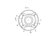
図6〜図8に、サスペンション機構を構成する自動車のロアアームと車体フレームの間に軸心が上下方向に沿う姿勢に設ける縦置きタイプのサスペンションブッシュ(防振装置に相当)を示してある。
【0028】
このサスペンションブッシュは、取付けボルトを挿通させる内筒1と、内筒1よりも薄肉で短かい外筒2とを、これらの間に介在するゴム状弾性体3(防振基体である)で連結し、内外筒1,2の径方向でゴム状弾性体3の中央部に、内筒1を挟んで位置する一対の中間板4,5を埋設し、ゴム状弾性体3にすぐり穴を形成して構成してある。15は内外筒1,2の軸心方向に貫通する空間部、14は、内筒1と外筒2との過度の相対変位を規制するストッパである。このストッパ14はゴム状弾性体から成る。
【0029】
後述するように中間板4,5はゴム状弾性体3のばね定数を自動車の前後方向で低く、幅方向(紙面の左右方向)で高く設定するための部材である。
【0030】
両中間板4は金属製で、図4,図5に示す第1実施形態の中間板4と同一形状である。繰り返して説明すると、図4,図5に示すように、各中間板4,5を内外筒1,2の周面に沿う湾曲状に形成し、内外筒1,2の軸心方向視における両端部10(内外筒1,2の周方向に対応する方向の中間板4,5の両端部10)を非波形の扁平状に形成するとともに、それらの間を頂部及び底部が円弧の波形状に形成してある。中間板4,5の前記両端部10はそれらの間の波形部11よりも内外筒1,2の軸心方向の一端側及び他端側に延出させてある。
【0031】
上記構造のサスペンションブッシュは、一対の中間板4,5が自動車の幅方向に並んだ状態になるようにロアアーム側の孔に圧入され、内筒3に挿通させた取付けボルトで車体フレームに取付け固定される。
【0032】
つまり、上記のサスペンションブッシュでは、ゴム状弾性体3に一対の中間板4,5を埋設することで、両中間板4,5が並ぶ方向のばね定数を上げ、これにより自動車の前後方向でばね定数を低く、自動車の幅方向でばね定数を高くして、自動車の乗り心地や操縦安定性を図っている。さらに中間板4,5を上記のように構成したことで[第1実施形態]の[イ]〜[ホ]と同様の作用を奏することができる。
【0033】
[別実施形態]
前記中間板4の波形部11は、頂部及び底部が円弧の波形に限られるものではなく、角形あるいは三角形の波形状に形成してあってもよい。
【0034】
【発明の効果】
請求項1の構成によれば、上記作用[イ]〜[ハ]により、車両の上下方向での乗り心地の低下等の不具合を招くことなく、軽量化や製作コストの低廉化を図ることができる防振装置を提供することができた。
【0035】
請求項1の構成によれば、上記作用[イ],[ニ],[ホ]により製作作業を簡単化でき、嵌合穴を波形にするための金型の改造を不要にすることができて、製作コストをより低廉化させることができた。
【0036】
請求項2の構成によれば、請求項1と同様の効果を得ることができるメンバーマウントを提供することができ、請求項3の構成によれば、請求項1と同様の効果を得ることができるサスペンションブッシュを提供することができた。
【図面の簡単な説明】
【図1】メンバーマウントの平面図
【図2】メンバーマウントの縦断正面図
【図3】メンバーマウントの底面図
【図4】中間板の平面図
【図5】中間板の背面図
【図6】サスペンションブッシュの平面図
【図7】図6のA−A断面図
【図8】図7のB−B断面図
【図9】従来のメンバーマウントの平面図
【図10】従来のメンバーマウントの縦断正面図
【図11】従来のメンバーマウントの底面図
【図12】従来の中間板の平面図
【図13】従来の中間板の背面図
【符号の説明】
1 内筒
2 外筒
3 ゴム状弾性体
4,5 中間板
10 中間板の両端部
11 波形部[0001]
BACKGROUND OF THE INVENTION
According to the present invention, an inner cylinder and an outer cylinder are connected by a rubber-like elastic body interposed between them, and a pair of intermediate plates located between the inner cylinder are embedded in the rubber-like elastic body. Relates to the device.
[0002]
[Prior art]
As an example of this type of vibration isolator, there are a member mount provided between a suspension member of an automobile and a vehicle body frame, and a suspension bush provided in a pivot portion of the suspension mechanism. In these vibration isolators, a pair of rubber elastic bodies are provided. By embedding the intermediate plate, the spring constant in the direction in which both intermediate plates are arranged is increased.
[0003]
A vibration isolator is attached to the vehicle body frame or the like so that the direction in which both intermediate plates are aligned is in the width direction of the automobile, thereby lowering the spring constant of the vibration isolator in the longitudinal direction of the automobile and increasing in the width direction of the automobile. In order to improve the ride comfort and handling stability of the car.
[0004]
By the way, if the intermediate plate is composed of a single thin metal plate in the above vibration isolator, the spring constant in the width direction of the automobile cannot be increased to a desired height. If it is made of a metal plate, the spring constant can be increased, but the weight is increased, and the spring constant in the front-rear direction of the automobile is easily increased. In addition, in the structure in which the single thick metal plate is reduced so that the weight can be reduced, the range in which the spring constant can be increased is reduced, and the ride comfort and handling stability of the automobile are sufficiently improved. I can't.
[0005]
Therefore, conventionally, as shown in FIGS. 9 to 13, the
[0006]
[Problems to be solved by the invention]
According to the above-described conventional configuration, there is a problem that the welding of the first intermediate
[0007]
As a technique for solving this problem, there is a technique in which a central portion of an intermediate plate made of a single metal plate is recessed in the radial direction of the inner and outer cylinders to form a recess [see Japanese Utility Model Publication No. 6-76730]. According to this technique, since the rubber-like elastic body portion in the recess is restrained from the inner surface of the recess and cannot function as an elastic body, the spring constant can be increased, and the weight can be reduced. Production costs can be reduced.
[0008]
However, in the above technique, the rubber-like elastic body portion in the concave portion is also restrained by the pair of upper and lower inner surfaces of the concave portion and cannot function as an elastic body in the vertical direction, and the spring constant in the vertical direction. The ride becomes higher and the ride comfort is lowered. Therefore, a new measure to lower the spring constant in the vertical direction is required.
[0009]
The present invention has been made in view of the above circumstances, and an object of the present invention is to prevent weight reduction and manufacturing cost reduction without causing problems such as a decrease in ride comfort in the vertical direction of the vehicle. The point is to provide a vibration device.
[0010]
[Means for Solving the Problems]
The structure of the invention according to
The inner cylinder and the outer cylinder are connected by a rubber-like elastic body interposed therebetween, and a pair of intermediate plates located between the inner cylinder are embedded in the rubber-like elastic body portion connecting the inner cylinder and the outer cylinder. Anti-vibration device
Forming the pair of intermediate plates in a wave shape when viewed in the axial direction of the inner and outer cylinders ;
The intermediate plate is formed in a curved shape along the circumferential surface of the inner and outer cylinders, and both end portions of the intermediate plate in a direction corresponding to the circumferential direction of the inner and outer cylinders are formed in a non-corrugated flat shape. The inner and outer cylinders are extended to one end side and the other end side in the axial direction.
[0012]
The structure of the invention according to
Lies in that is configured to a member mount provided between the suspension members and the body frame.
[0013]
The configuration of the invention according to
The suspension bush is provided in the suspension mechanism.
[0014]
DETAILED DESCRIPTION OF THE INVENTION
Hereinafter, embodiments of the present invention will be described with reference to the drawings.
[0015]
[First embodiment]
1 to 3, a member mount for an automobile that reduces vibration input and suppresses vibration in a state where it is assembled to a vehicle body frame and a suspension member below the vehicle body frame. Equivalent).
[0016]
This member mount includes an
[0017]
The structure of each part will be described. The
[0018]
Both the
[0019]
As shown in FIG. 2, the member mount having the above structure has a vertical posture in which the
[0020]
That is, in the above-described member mount, by embedding the pair of
[0021]
[A] Since the
[0022]
[B] As a means for increasing the spring constant of the rubber-like
[0023]
[C] Since the rubber-like elastic body is not restrained in the axial direction (vertical direction) of the inner and
[0024]
[D] When manufacturing the member mount having the above structure, the inner and
[0025]
In this manufacturing process, the
[0026]
[E] Since both
[0027]
[Second Embodiment]
FIG. 6 to FIG. 8 show a vertically installed suspension bush (corresponding to a vibration isolator) provided between the lower arm of the automobile constituting the suspension mechanism and the vehicle body frame in a posture along the vertical direction.
[0028]
This suspension bush connects an
[0029]
As will be described later, the
[0030]
Both
[0031]
The suspension bush having the above structure is fixedly attached to the vehicle body frame with a mounting bolt that is press-fitted into the hole on the lower arm side so that the pair of
[0032]
In other words, in the suspension bush described above, the pair of
[0033]
[Another embodiment]
The
[0034]
【The invention's effect】
According to the configuration of the first aspect, the above actions [A] to [C] can reduce the weight and the manufacturing cost without causing problems such as a decrease in riding comfort in the vertical direction of the vehicle. It was possible to provide an anti-vibration device.
[0035]
According to the configuration of the first aspect, the manufacturing operation can be simplified by the above actions [A], [D], and [E], and it is not necessary to modify the mold for making the fitting hole corrugated. As a result, the production cost could be further reduced.
[0036]
According to the second aspect, it is possible to provide a member mount can provide the same effect as
[Brief description of the drawings]
[Fig. 1] Plan view of member mount [Fig. 2] Front view of member mount longitudinally [Fig. 3] Bottom view of member mount [Fig. 4] Plan view of intermediate plate [Fig. 5] Rear view of intermediate plate [Fig. FIG. 7 is a sectional view taken along the line AA in FIG. 6. FIG. 8 is a sectional view taken along the line BB in FIG. 7. FIG. 9 is a plan view of the conventional member mount. Front view [Fig. 11] Bottom view of conventional member mount [Fig. 12] Plan view of conventional intermediate plate [Fig. 13] Rear view of conventional intermediate plate [Explanation of symbols]
DESCRIPTION OF
Claims (3)
前記一対の中間板を内外筒の軸心方向視で波形状に形成し、
前記中間板を前記内外筒の周面に沿う湾曲状に形成し、前記内外筒の周方向に対応する方向の前記中間板の両端部を非波形の扁平状に形成して、波形部よりも前記内外筒の軸心方向の一端側及び他端側に延出させてある防振装置。The inner cylinder and the outer cylinder are connected by a rubber-like elastic body interposed therebetween, and a pair of intermediate plates located between the inner cylinder are embedded in the rubber-like elastic body portion connecting the inner cylinder and the outer cylinder. Anti-vibration device
Forming the pair of intermediate plates in a wave shape when viewed in the axial direction of the inner and outer cylinders ;
The intermediate plate is formed in a curved shape along the circumferential surface of the inner and outer cylinders, and both end portions of the intermediate plate in a direction corresponding to the circumferential direction of the inner and outer cylinders are formed in a non-corrugated flat shape. A vibration isolator extending to one end side and the other end side in the axial direction of the inner and outer cylinders .
Priority Applications (1)
| Application Number | Priority Date | Filing Date | Title |
|---|---|---|---|
| JP2002243204A JP3696580B2 (en) | 2002-08-23 | 2002-08-23 | Vibration isolator |
Applications Claiming Priority (1)
| Application Number | Priority Date | Filing Date | Title |
|---|---|---|---|
| JP2002243204A JP3696580B2 (en) | 2002-08-23 | 2002-08-23 | Vibration isolator |
Publications (2)
| Publication Number | Publication Date |
|---|---|
| JP2004084708A JP2004084708A (en) | 2004-03-18 |
| JP3696580B2 true JP3696580B2 (en) | 2005-09-21 |
Family
ID=32052020
Family Applications (1)
| Application Number | Title | Priority Date | Filing Date |
|---|---|---|---|
| JP2002243204A Expired - Fee Related JP3696580B2 (en) | 2002-08-23 | 2002-08-23 | Vibration isolator |
Country Status (1)
| Country | Link |
|---|---|
| JP (1) | JP3696580B2 (en) |
Families Citing this family (6)
| Publication number | Priority date | Publication date | Assignee | Title |
|---|---|---|---|---|
| JP5303126B2 (en) * | 2007-07-31 | 2013-10-02 | 東洋ゴム工業株式会社 | Axle spring for rolling stock |
| JP2010276108A (en) * | 2009-05-28 | 2010-12-09 | Kurashiki Kako Co Ltd | Strut mount |
| JP5373584B2 (en) * | 2009-12-17 | 2013-12-18 | 株式会社ブリヂストン | Elastic bush |
| CN103633408A (en) * | 2013-08-27 | 2014-03-12 | 苏州工业园区凯艺精密科技有限公司 | Isolator cavity side plate positioning device and isolator cavity processing machine |
| KR102512791B1 (en) * | 2021-06-29 | 2023-03-31 | 주식회사 세명기업 | Stabilizer bar bush |
| CN115042862B (en) * | 2022-07-11 | 2023-10-31 | 奇瑞汽车股份有限公司 | Sub vehicle frame assembly and vehicle |
-
2002
- 2002-08-23 JP JP2002243204A patent/JP3696580B2/en not_active Expired - Fee Related
Also Published As
| Publication number | Publication date |
|---|---|
| JP2004084708A (en) | 2004-03-18 |
Similar Documents
| Publication | Publication Date | Title |
|---|---|---|
| US8628101B2 (en) | Suspension structure, bush structure and suspension characteristic adjusting method | |
| JP4841923B2 (en) | Strut mount | |
| CN105377594A (en) | Vehicle suspension and leaf spring therefore | |
| JP4140904B2 (en) | Axle with anti-vibration rubber | |
| US20070131469A1 (en) | Power train mounting apparatus of vehicle | |
| JP3809583B2 (en) | Front wheel suspension using steering gear frame | |
| JP3696580B2 (en) | Vibration isolator | |
| CN210478324U (en) | H-arm assembly structure of automobile suspension | |
| KR101302328B1 (en) | Lower control arm assembly for front suspension system | |
| US10577021B2 (en) | Vehicle sub-frame | |
| JP2588784Y2 (en) | Vehicle suspension mounting rubber | |
| JP3175523B2 (en) | Aluminum alloy cross member | |
| JP4998294B2 (en) | Suspension device | |
| JP2018169013A (en) | Cylindrical vibration-proof device | |
| JPH01126447A (en) | Vibration-isolating mount | |
| JPS6031930Y2 (en) | Forklift rear axle suspension system | |
| JP2001082139A (en) | Support device for exhaust system of vehicle | |
| JP4255006B2 (en) | Upper bracket mounting structure of cab suspension system | |
| JP3477422B2 (en) | bracket | |
| JP5530398B2 (en) | Suspension structure and suspension characteristics adjustment method | |
| JPH0885318A (en) | Mounting structure for shock absorber | |
| JPH0714128Y2 (en) | Cab mount | |
| KR100452203B1 (en) | Low arm with difference thickness in suspension | |
| JPH031350Y2 (en) | ||
| JP3998086B2 (en) | Support structure for vehicle transmission |
Legal Events
| Date | Code | Title | Description |
|---|---|---|---|
| A977 | Report on retrieval |
Free format text: JAPANESE INTERMEDIATE CODE: A971007 Effective date: 20041227 |
|
| A131 | Notification of reasons for refusal |
Free format text: JAPANESE INTERMEDIATE CODE: A131 Effective date: 20050118 |
|
| A521 | Written amendment |
Free format text: JAPANESE INTERMEDIATE CODE: A523 Effective date: 20050309 |
|
| TRDD | Decision of grant or rejection written | ||
| A01 | Written decision to grant a patent or to grant a registration (utility model) |
Free format text: JAPANESE INTERMEDIATE CODE: A01 Effective date: 20050628 |
|
| A61 | First payment of annual fees (during grant procedure) |
Free format text: JAPANESE INTERMEDIATE CODE: A61 Effective date: 20050629 |
|
| R150 | Certificate of patent (=grant) or registration of utility model |
Free format text: JAPANESE INTERMEDIATE CODE: R150 |
|
| FPAY | Renewal fee payment (prs date is renewal date of database) |
Free format text: PAYMENT UNTIL: 20080708 Year of fee payment: 3 |
|
| FPAY | Renewal fee payment (prs date is renewal date of database) |
Free format text: PAYMENT UNTIL: 20090708 Year of fee payment: 4 |
|
| FPAY | Renewal fee payment (prs date is renewal date of database) |
Free format text: PAYMENT UNTIL: 20090708 Year of fee payment: 4 |
|
| FPAY | Renewal fee payment (prs date is renewal date of database) |
Free format text: PAYMENT UNTIL: 20100708 Year of fee payment: 5 |
|
| FPAY | Renewal fee payment (prs date is renewal date of database) |
Free format text: PAYMENT UNTIL: 20110708 Year of fee payment: 6 |
|
| FPAY | Renewal fee payment (prs date is renewal date of database) |
Free format text: PAYMENT UNTIL: 20120708 Year of fee payment: 7 |
|
| FPAY | Renewal fee payment (prs date is renewal date of database) |
Free format text: PAYMENT UNTIL: 20140708 Year of fee payment: 9 |
|
| LAPS | Cancellation because of no payment of annual fees |