JP3695148B2 - Control device for restarting vehicle engine - Google Patents
Control device for restarting vehicle engine Download PDFInfo
- Publication number
- JP3695148B2 JP3695148B2 JP16255198A JP16255198A JP3695148B2 JP 3695148 B2 JP3695148 B2 JP 3695148B2 JP 16255198 A JP16255198 A JP 16255198A JP 16255198 A JP16255198 A JP 16255198A JP 3695148 B2 JP3695148 B2 JP 3695148B2
- Authority
- JP
- Japan
- Prior art keywords
- engine
- restart
- predetermined
- clutch
- time
- Prior art date
- Legal status (The legal status is an assumption and is not a legal conclusion. Google has not performed a legal analysis and makes no representation as to the accuracy of the status listed.)
- Expired - Lifetime
Links
Images


Classifications
-
- Y—GENERAL TAGGING OF NEW TECHNOLOGICAL DEVELOPMENTS; GENERAL TAGGING OF CROSS-SECTIONAL TECHNOLOGIES SPANNING OVER SEVERAL SECTIONS OF THE IPC; TECHNICAL SUBJECTS COVERED BY FORMER USPC CROSS-REFERENCE ART COLLECTIONS [XRACs] AND DIGESTS
- Y02—TECHNOLOGIES OR APPLICATIONS FOR MITIGATION OR ADAPTATION AGAINST CLIMATE CHANGE
- Y02T—CLIMATE CHANGE MITIGATION TECHNOLOGIES RELATED TO TRANSPORTATION
- Y02T10/00—Road transport of goods or passengers
- Y02T10/80—Technologies aiming to reduce greenhouse gasses emissions common to all road transportation technologies
- Y02T10/84—Data processing systems or methods, management, administration
Abstract
Description
【0001】
【発明が属する技術分野】
本発明は、所定の停止条件が成立したときにエンジンを自動停止するとともに、所定の再始動条件が成立したときに該自動停止したエンジンを再始動する車両であって、該再始動の際に変速機の所定のクラッチを係合させる車両のエンジン再始動時の制御装置に関する。
【0002】
【従来の技術】
従来、走行中において車両が停止し、且つ所定の停止条件が成立した場合に、エンジンを自動的に停止させ、燃料の節約、排気エミッションの低減、あるいは騒音の低減等を図るように構成した車両が提案され、すでに実用化されている(例えば特開平8−14076号公報)。
【0003】
このような車両にあっては、運転者がアクセルペダルを踏むなどの走行の意思を示して所定の再始動条件が成立したときには、直ちにエンジンを再始動させる必要がある。
【0004】
ところが、自動変速機が油圧式の自動変速機であった場合には、エンジンが停止すると該エンジンと連結されているオイルポンプも停止してしまうため、例えば自動変速機の前進クラッチ(所定のクラッチ)に供給されているオイルも油路から抜け、油圧が低下してしまう。そのため、エンジンが再始動されるときには、当該前進走行時に係合されるべき前進クラッチもその係合状態が解かれてしまった状態となってしまうことになる。
【0005】
この場合、エンジンが再始動された時に、この前進クラッチが速やかに係合されないと、いわばニュートラルの状態のままアクセルペダルが踏み込まれることになり、エンジンが吹き上がった状態で前進クラッチが係合してしまうため、係合ショックが発生する可能性がある。
【0006】
そのため、このような状態が発生しないように、前記特開平8−14076号公報にかかる車両においては、エンジンが自動停止してから再始動されるまでの間、大型のアキュムレータの機能により前進クラッチを係合状態に維持する技術を提案している。
【0007】
また特開平9−39613号公報では、エンジンを完全に停止させてしまうのではなく、該エンジンの燃料の供給のみを停止し、モータジェネレータを駆動させて、該エンジンをほぼアイドリング回転速度に保持し、オイルポンプが停止しないように配慮した技術を提案している。
【0008】
【発明が解決しようとする課題】
しかしながら、前記特開平8−14076号公報にて提案された技術のように、大型のアキュムレータを組み込むことにより、エンジンが停止中においても前進クラッチを係合状態に維持するという技術は、例えばD(ドライブ)ポジションからN(ニュートラル)ポジションへのシフト時のドレン性能の悪化、即ち、前進クラッチの解放スピードが遅くなることや、油圧制御装置の大型化など、アキュムレータを設けることにより新たな弊害が発生するのが避けられなかった。
【0009】
また、前記特開平9−39613号公報にて提案された技術のように、モータジェネレータによってエンジンをアイドリング回転速度に維持するという技術は、燃費の向上は図れるものの、モータジェネレータを駆動する必要があるためバッテリの消耗が著しく、そのためバッテリを大型化(大容量化)する必要があるという問題があった。
【0010】
本発明は、このような従来の問題に鑑みてなされたものであって、ドレン性能の悪化や油圧制御装置あるいはバッテリの大型化などの新たな不具合を一切生じることなく、エンジン再始動時に、自動変速機の変速比がいかなる場合にも、係合ショック等を生じることなく速やかに所定のクラッチを係合させることのできる車両の再始動時の制御装置を提供することをその課題とする。
【0011】
【課題を解決するための手段】
請求項1に記載の発明は、所定の停止条件が成立したときにエンジンを自動停止するとともに、所定の再始動条件が成立したときに該自動停止したエンジンを再始動する車両であって、変速段を設定するのに必要とするオイルの量が変速段によって異なる変速機を備え、前記再始動の際に前記変速機の所定のクラッチを係合させる車両のエンジン再始動時の制御装置において、エンジンの再始動時に前記所定のクラッチを係合させるための油圧を供給する際に、該油圧の供給初期に一時的に油圧を急速に増圧する急速増圧制御を実行する手段を備え、該急速増圧制御の実行態様をエンジンの再始動時に達成される変速段および前記所定のクラッチの油路の圧力に応じて変更することにより、上記課題を解決したものである。
また、請求項2に記載の発明は、所定の停止条件が成立したときにエンジンを自動停止するとともに、所定の再始動条件が成立したときに該自動停止したエンジンを再始動する車両であって、変速段を設定するのに必要とするオイルの量が変速段によって異なる変速機を備え、前記再始動の際に前記変速機の所定のクラッチを係合させる車両のエンジン再始動時の制御装置において、エンジンの再始動時に前記所定のクラッチを係合させるための油圧を供給する際に、該油圧の供給初期に一時的に油圧を急速に増圧する急速増圧制御を実行する手段を備え、該急速増圧制御の実行態様をエンジンの再始動時に達成される変速段および前記エンジン停止時のオイルの抜け量に応じて変更することにより、上記課題を解決したものである。
さらに、請求項3に記載の発明は、所定の停止条件が成立したときにエンジンを自動停止するとともに、所定の再始動条件が成立したときに該自動停止したエンジンを再始動する車両であって、該再始動の際に変速機の所定のクラッチを係合させる車両のエンジン再始動時の制御装置において、エンジンの再始動時に前記所定のクラッチを係合させるための油圧を供給する際に、該油圧の供給初期に一時的に油圧を急速に増圧する急速増圧制御を実行する手段を備え、該急速増圧制御の実行態様をエンジンの再始動時に達成される変速段に応じて変更するとともにその急速増圧制御を前記エンジンの再始動指令後にエンジンの回転数が所定値に立ち上がった時点に開始することを特徴とする制御装置である。
【0012】
なお、ここでいう「所定のクラッチ」とは、エンジンの再始動時に係合されるクラッチを指すものであり、有段自動変速機においては例えばいわゆる「前進クラッチ」等がこれに相当する。なお、無段変速機では例えば「発進クラッチ」が該「所定のクラッチ」に相当する。又、自動クラッチ付のマニュアル変速機の場合は、該「自動クラッチ」が「所定のクラッチ」に相当する。
【0013】
又、ここでいう「急速増圧制御」とは、所定のクラッチにオイルを供給する際に、オイルの供給速度(油圧上昇)を通常供給時と比べて速くなるように制御することである。なお、オイルの供給速度を速くするためには、例えば、ライン圧の制御目標圧を高く設定したり、又、油路の絞りを緩くするなどの手法を採用すればよい。
【0014】
更に、ここでいう「変速段」とは、有段変速機では「変速段」又は「ギヤ段」を指し、無段変速機では伝動ベルトの係り径の変更により決定される「変速比」を指すものとする。
【0015】
なお、前記急速増圧制御の実行態様は、該急速増圧制御の実行時間を変更することにより変更してもよく(請求項4)、又、該急速増圧制御の油圧の制御目標値を変更することにより変更してもよい(請求項5)。
【0016】
一方、請求項6に記載の発明は、所定の停止条件が成立したときにエンジンを自動停止するとともに、所定の再始動条件が成立したときに該自動停止したエンジンを再始動する車両であって、変速段を設定するのに必要とするオイルの量が変速段によって異なる変速機を備え、前記再始動の際に前記変速機の所定のクラッチを係合させる車両のエンジン再始動時の制御装置において、エンジンの再始動時に前記所定のクラッチを係合させるための油圧を供給する際に、該油圧の供給初期に一時的に油圧を急速に増圧する急速増圧制御を実行する手段と、再始動時に達成される変速段においてエンジンブレーキを確保するために係合される摩擦係合装置が再始動時に前記所定のクラッチと同時に係合されるか否かを判断する手段と、を備え、前記急速増圧制御の実行態様を、該判断により前記エンジンブレーキを確保するために係合される摩擦係合装置が再始動時に係合されるか否かおよび前記所定のクラッチの油路の圧力に基づいて、変更することにより、同様に上記課題を解決したものである。
また、請求項7に記載の発明は、所定の停止条件が成立したときにエンジンを自動停止するとともに、所定の再始動条件が成立したときに該自動停止したエンジンを再始動する車両であって、変速段を設定するのに必要とするオイルの量が変速段によって異なる変速機を備え、前記再始動の際に前記変速機の所定のクラッチを係合させる車両のエンジン再始動時の制御装置において、エンジンの再始動時に前記所定のクラッチを係合させるための油圧を供給する際に、該油圧の供給初期に一時的に油圧を急速に増圧する急速増圧制御を実行する手段と、再始動時に達成される変速段においてエンジンブレーキを確保するために係合される摩擦係合装置が再始動時に前記所定のクラッチと同時に係合されるか否かを判断する手段と、を備え、前記急速増圧制御の実行態様を、該判断により前記エンジンブレーキを確保するために係合される摩擦係合装置が再始動時に係合されるか否かおよび前記エンジン停止時のオイルの抜け量に基づいて、変更することにより、同様に上記課題を解決したものである。
さらに、請求項8に記載の発明は、所定の停止条件が成立したときにエンジンを自動停止するとともに、所定の再始動条件が成立したときに該自動停止したエンジンを再始動する車両であって、該再始動の際に変速機の所定のクラッチを係合させる車両のエンジン再始動時の制御装置において、エンジンの再始動時に前記所定のクラッチを係合させるための油圧を供給する際に、該油圧の供給初期に一時的に油圧を急速に増圧する急速増圧制御を実行する手段と、再始動時に達成される変速段においてエンジンブレーキを確保するために係合される摩擦係合装置が再始動時に前記所定のクラッチと同時に係合されるか否かを判断する手段と、を備え、前記急速増圧制御の実行態様を、該判断により前記エンジンブレーキを確保するために係合される摩擦係合装置が再始動時に係合されるか否かに基づいて、変更するとともにその急速増圧制御を前記エンジンの再始動指令後にエンジンの回転数が所定値に立ち上がった時点に開始することにより、同様に上記課題を解決したものである。
【0017】
この場合も前記急速増圧制御の実行態様を、該急速増圧制御の実行時間を変更することにより変更してもよく(請求項9)、また、該急速増圧制御の油圧の制御目標値を変更することにより変更してもよい(請求項10)。
【0018】
本発明においては、上述した不具合を解消するために、大型のアキュムレータを設けたり、あるいは、車両停止中においてもエンジンを回転させておいて、所定のクラッチを係合状態に維持しておくのではなく、エンジン再始動と同時に所定のクラッチを係合させるためのオイルの供給を開始することとし、その際、該油圧を供給するにあたって、クラッチをできるだけ速く係合させるため、一時的に所定時間だけオイルの急速増圧制御を実行するようにした。
【0019】
しかしながら、エンジンは始動を開始し、エンジン回転速度はすでに上昇段階にあるため、もし、この急速増圧制御が適正に実行されないと、該所定のクラッチが係合されるときに大きな係合ショックが発生する虞れがある。
【0020】
そのため本発明では、急速増圧制御の実行態様をエンジン再始動時の「変速段」毎に、また「所定のクラッチの油路の圧力」あるいは「エンジン停止時のオイルの抜け量」に応じて変更する。無段変速機の場合は、達成される変速比が異なると油圧をシーブに供給すべきオイルの量が異なるため、やはり最適な態様が異なる。
また、本発明では、急速増圧制御の実行態様をエンジン再始動時の「変速段」に応じて変更することに加えて、その急速増圧制御の開始時点をエンジン再始動指令後にエンジン回転数が所定値に立ち上がった時点とする。そのため、ばらつきのない安定したオイルの供給制御が可能になる。
【0021】
同様に、同じ変速段でも、エンジンブレーキを確保するためのクラッチが係合するか否かによっても最適な態様が異なってくる。本発明によりどういう状態でエンジンを再始動し、発進するとしても、最適な急速増圧制御を実行することができるようになり、係合ショックを発生することなくクラッチを速やかに係合させることができる。
【0022】
【発明の実施の形態】
以下、図面を参照しながら本発明の実施形態を詳細に説明する。
【0023】
本実施形態では、「変速段」を持つ有段自動変速機を例に挙げて説明する。
【0024】
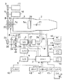
本実施形態では、図2に示されるような車両の駆動システムにおいて、所定の停止条件が成立したときにエンジンを自動停止させるとともに、所定の再始動条件が成立したときに該自動停止したエンジンを再始動させるようにしている。エンジンが停止するとオイルポンプも停止して自動変速機の前進クラッチ(所定のクラッチ)の係合状態が解かれるため、エンジン再始動の際に該前進クラッチをできるだけ速く係合させる必要がある。それは、前述したようにエンジンがニュートラルの状態で吹き上がるのを防止するためであり、また、車両の発進体勢を早く整えるためである。むろん、発進クラッチを持つ無段変速機にも同様なことがいえる。
【0025】
図2において、1は車両に搭載されるエンジン、2は自動変速機である。このエンジン1には該エンジン1を再始動させるためのモータ及び発電機として機能するモータジェネレータ3が、該エンジン1のクランク軸1aに、電磁クラッチ26、プーリ22、ベルト8、プーリ23及び減速機構Rを介して連結されている。
【0026】
減速機構Rは、遊星歯車式で、サンギア33、キャリア34、リングギア35を含み、ブレーキ31、クラッチ32を介してモータジェネレータ3及びプーリ23の間に組込まれている。なお、クラッチ32はワンウェイクラッチに置き換えることができる。
【0027】
自動変速機用2のオイルポンプ19は、従来通りエンジン1のクランク軸1aに直結されている。なお、想像線Pで囲まれた構成のように、オイルポンプ19′を電磁クラッチ27を介してモータジェネレータ3と連結して設け、独自の入口配管24、出口配管25によりオイルを自動変速機2に供給するような構成としてもよい。自動変速機2内には前進走行時に係合される公知の前進クラッチC1が設けられている。
【0028】
図の符号11、16は補機類で、例えばそれぞれパワーステアリング用のポンプ、エアコン用のコンプレッサー等に相当しており、エンジン1のクランク軸1a及びモータジェネレータ3とはプーリ9、14とベルト8によって連結されている。
【0029】
図2には図示していないが、補機類としては前記のほかに、エンジンオイルポンプ、エンジンウォータポンプ等も連結されている。符号4はモータジェネレータ3に電気的に接続されるインバータである。このインバータ4はスイッチングにより電力源であるバッテリ5からモータジェネレータ3への電気エネルギの供給を可変にしてモータジェネレータ3の回転速度を可変にする。また、モータジェネレータ3からバッテリ5への電気エネルギの充電を行うように切り換える。
【0030】
符号7は電磁クラッチ26、27の断続の制御、及びインバータ4のスイッチング制御を行うためのコントローラである。コントローラ7へは入力信号としてエンジン回転速度センサ49からのエンジン回転速度信号(=オイルポンプの回転速度信号)、自動停止走行モード(エコランモード)のスイッチ40の信号、エアコン作動のスイッチ42の信号、シフトレバー44のシフトポジションを検出するセンサ45からの信号、油温を推定検出するためのセンサの機能を兼ねたエンジン冷却水温センサ47、ブレーキがかかっているか否かを検出するブレーキ検出センサ43からの信号等が入力される。図中の矢印線は各信号線を示している。
【0031】
次に、上記自動変速機2における自動変速システムの具体的な一例を説明する。
【0032】
図3は、自動変速機2のスケルトン図である。
【0033】
この自動変速機2は、トルクコンバータ111、副変速部112及び主変速部113を備える。
【0034】
前記トルクコンバータ111は、ロックアップクラッチ124を備える。このロックアップクラッチ124は、ポンプインペラ126に一体化させてあるフロントカバー127とタービンランナ128を一体に取付けた部材(ハブ)129との間に設けられている。
【0035】
エンジン1のクランク軸1aは、フロントカバー127に連結されている。タービンランナ128に連結された入力軸130は、副変速部112を構成するオーバードライブ用遊星歯車機構131のキャリヤ132に連結されている。
【0036】
この遊星歯車機構131におけるキャリヤ132とサンギヤ133との間には、クラッチC0 と一方向クラッチF0 とが設けられている。この一方向クラッチF0 はサンギヤ133がキャリヤ132に対して相対的に正回転(入力軸130の回転方向の回転)する場合に係合するようになっている。
【0037】
一方、サンギヤ133の回転を選択的に止めるブレーキB0 が設けられている。又、この副変速部112の出力要素であるリングギヤ134が、主変速部113の入力要素である中間軸135に接続されている。
【0038】
副変速部112は、クラッチC0 もしくは一方向クラッチF0 が係合した状態では遊星歯車機構131の全体が一体となって回転するため、中間軸135が入力軸130と同速度で回転する。又ブレーキB0 を係合させてサンギヤ133の回転を止めた状態では、リングギヤ134が入力軸130に対して増速されて正回転する。即ち、副変速部112はハイ・ローの2段の切換えを設定することができる。
【0039】
前記主変速部113は三組の遊星歯車機構140、150、160を備えており、これらの歯車機構140、150、160が以下のように連結されている。
【0040】
即ち、第1遊星歯車機構140のサンギヤ141と第2遊星歯車機構150のサンギヤ151とが互いに一体的に連結され、第1遊星歯車機構140のリングギヤ143と第2遊星歯車機構150のキャリヤ152と第3遊星歯車機構160のキャリヤ162との三者が連結されている。又、第3遊星歯車機構160のキャリヤ162に出力軸170が連結されている。更に第2遊星歯車機構150のリングギヤ153が第3遊星歯車機構160のサンギヤ161に連結されている。
【0041】
この主変速部113の歯車列では後進1段と前進4段とを設定することができ、そのためのクラッチ及びブレーキが以下のように設けられている。
【0042】
即ち、第2遊星歯車機構150のリングギヤ153及び第3遊星歯車機構160のサンギヤ161と中間軸135との間に前進クラッチC1 が設けられ、又第1遊星歯車機構140のサンギヤ141及び第2遊星歯車機構150のサンギヤ151と中間軸135との間にクラッチC2 が設けられている。
【0043】
第1遊星歯車機構140及び第2遊星歯車機構150のサンギヤ141、151の回転を止めるブレーキB1 が配置されている。又、これらのサンギヤ141、151とケーシング171との間には、一方向クラッチF1 とブレーキB2 とが直列に配列されている。一方向クラッチF1 はサンギヤ141、151が逆回転(入力軸135の回転方向とは反対方向の回転)しようとする際に係合するようになっている。
【0044】
第1遊星歯車機構140のキャリヤ142とケーシング171との間にはブレーキB3 が設けられている。又、第3遊星歯車機構160のリングギヤ163の回転をとめる要素としてブレーキB4 と、一方向クラッチF2 とがケーシング171との間に並列に配置されている。なお、この一方向クラッチF2 はリングギヤ163が逆回転しようとする際に係合するようになっている。
【0045】
上記の自動変速機2では、結局後進1段と前進5段の変速を行うことができる。この5つの変速段を設定するための各クラッチ及びブレーキ(摩擦係合装置)の係合作動表を図4に示す。図4において、○印は係合状態、◎印はエンジンブレーキを確保すべきときにのみ係合状態、△印は係合するが動力伝達に関係なし、空欄は解放状態をそれぞれ示している。
【0046】
自動変速機のシフトポジションが「D」の状態であるときには、通常、自動的に「1st」からスタートするように制御されている。
【0047】
近年になり様々な自動変速機の制御方法が提案・実用化されており、図8に示すようなゲート式の自動変速機では、「D」ポジションの右側にある「M」(マニュアル)のゲートにシフトレバー44を移動させることにより、図9に示すステアリング180に設置されたボタン200、202を押すことにより、手元操作でシフトアップ及びシフトダウンのシフトチェンジの操作が可能でとなり、ドライバのマニュアル操作で例えば2nd、3rd発進ができる。又、特にこのゲート式だけに限定されるわけではないが、シフトレバー44を固定の2nd、3rdに操作することにより、発進時にマニュアル操作で2nd、3rdといった固定ポジションでの発進も可能である。
【0048】
つまり、ドライバのマニュアル操作によって必ずしも「D」ポジションの1stから発進するとは限らない場合がある。
【0049】
図4に示すように、エンジン始動中に「N」ポジションから「D」ポジションの1stに移行するときは、クラッチC1のみに対しオイルを供給すればよいが、エンジン1が停止した状態から再始動によって「D」ポジションの1stから発進する場合には、クラッチC1に加えクラッチC0も同時に係合させなければならない。又、発進時にマニュアルモードで固定ポジションの2nd、3rd・・・を選択すると、クラッチやブレーキの係合する種類と数が異なる(後に詳述)。
【0050】
そのため、本実施形態では、クラッチやブレーキの係合する種類と数に応じて急速増圧制御を行う際のオイルの供給量を制御するようにする。
【0051】
なお、同様な趣旨により、もし、採用している変速機が無段変速機の場合は、該無段変速機を最低変速比側からスタートさせないときがあることを考慮し、再始動と同時に達成する「変速比」に応じて油圧シーブに供給すべきオイルの量が異なることに着目し、急速増圧制御を行う際のオイルの供給態様を制御するようにする。
【0052】
図3に戻り、各クラッチ及びブレーキ(摩擦係合装置)の係合あるいは解放には、油圧制御装置75内のソレノイドバルブS1、S2、S3、S4、SLN、SLT、SLUが、A/Tコントローラ80からの指令に基づいて駆動制御されることによって実行される。
【0053】
ここで、S1、S2、S3はシフト用ソレノイドバルブ、S4はエンジンブレーキ作動用ソレノイドバルブ、SLNはアキュムレータ背圧制御用のソレノイドバルブ、SLTはライン圧制御用のソレノイドバルブ、SLUはロックアップ用ソレノイドバルブを示す。
【0054】
A/Tコントロールコンピュータ80は、前述したコントローラ7とリンクしており、各種センサ群90からの信号が入力されソレノイドバルブ等を制御し、各クラッチ及びブレーキ(摩擦係合装置)の係合あるいは解放が行えるようにしている。
【0055】
次に、上記自動変速機2において前進クラッチC1を係合させる構成について図5を用いて説明する。
【0056】
図5は自動変速機の油圧制御装置75において前進クラッチC1を係合させる構成の要部を示す油圧回路図である。
【0057】
プライマリレギュレータバルブ50は、ライン圧コントロールソレノイド52によって制御され、オイルポンプ19によって発生された元圧をライン圧PLに調圧する。このライン圧PLは、マニュアルバルブ54に導かれる。マニュアルバルブ54は、シフトレバー44と機械的に接続され、ここでは、前進ポジション、例えば、Dポジション、あるいはマニュアルポジションの1st、2nd等が選択されたときにライン圧PLを前進クラッチC1側に連通させる。
【0058】
マニュアルバルブ54と前進クラッチC1との間には大オリフィス56と切換弁58が介在されている。切換弁58はソレノイド60によって制御され、大オリフィス56を通過してきたオイルを選択的に前進クラッチC1に導いたり遮断したりする。
【0059】
切換弁58をバイパスするようにしてチェックボール62と小オリフィス64が並列に組み込まれており、切換弁58がソレノイド60によって遮断されたときには大オリフィス56を通過してきたオイルは更に小オリフィス64を介して前進クラッチC1に到達するようになっている。なお、チェックボール62は前進クラッチC1の油圧がドレンされるときに該ドレンが円滑に行われるように機能する。
【0060】
切換弁58と前進クラッチC1との間の油路66には、オリフィス68を介してアキュムレータ70が配置されている。このアキュムレータ70はピストン72及びスプリング74を備え、前進クラッチC1にオイルが供給されるときに、スプリング74によって決定される所定の油圧にしばらく維持されるように機能し、前進クラッチC1の係合終了付近で発生するショックを低減する。
【0061】
次にこの実施形態の作用を説明する。
【0062】
エンジン始動時には電磁クラッチ26が接続状態とされ、モータジェネレータ3を駆動してエンジンを始動する。このときブレーキ31をオンにし、クラッチ32をオフにすることでモータジェネレータ3の回転は減速機構Rのサンギア33側からキャリア34側に減速して伝達される。これにより、モータジェネレータ3とインバータ4の容量を小さくしてもエンジン1をクランキングするのに必要な駆動力を確保できる。エンジン1の始動後は、モータジェネレータ3は発電機として機能し、例えば車両の制動時においてバッテリ5に電気エネルギを蓄える。エンジン始動時にはモータジェネレータ3の回転速度をコントローラ7が検出し、インバータ4に対し、モータジェネレータ3の回転がエンジン1を始動するのに必要なトルクと回転速度となるようにスイッチング信号を出力する。例えばエンジン始動時にエアコンスイッチ42の信号がオンとなっていれば、エアコンオフ時に比べてより大きなトルクが必要であるから、コントローラ7は大きなトルク及び回転速度でモータジェネレータ3が回転できるようにスイッチング信号を出力する。
【0063】
エコランモード信号がオンとなった状態で車両が停止し、且つ所定のエンジン停止条件が成立すると、コントローラ7はエンジン1に燃料の供給をカットする信号を出力し、エンジン1を停止させる。なお、燃料の供給カットの出力信号線は図2では省略されている。エコランモード信号は、車室内に設けられたエコランスイッチ42を運転者が押すことによってコントローラ7に入力される。
【0064】
なお、本実施形態では、エンジン1の停止条件を「車速が零」、「アクセルオフ」、「ブレーキオン」、「シフトポジションが非駆動ポジションである」とし、且つ、「これらの条件が連続して所定時間Tstopが経過」としている。この所定時間Tstopはタイマによりカウントされるようになっており、コントローラ7及びA/Tコントローラ80に入力され処理される。
【0065】
なお、この所定時間Tstopはエンジンの自動停止を開始するまでの時間に相当し、状況に応じて変更・設定可能である。この所定時間Tstopを零に設定し、所定の停止条件が整い次第すぐにエンジンの自動停止を行ってもよく、また、無限大に設定してエンジンの自動停止を実質的に禁止するようにもできる。
【0066】
エンジン1が自動停止した後には、コントローラ7は電磁クラッチ26に切断の制御信号を出力しており、プーリ22とエンジン1とは動力非伝達状態にある。一方、エンジン1が停止中でもエアコンやパワーステアリングは作動させておきたいため、パワーステアリング用ポンプ、エアコン用コンプレッサの負荷等が考慮されたトルクでモータジェネレータ3が回転するように、コントローラ7はインバータ4に対して相応のスイッチング信号を出力する。
【0067】
なお、このときブレーキ31をオフにし、クラッチ32をオンとし、電磁クラッチ26をオフとしておく。このような状態とすることにより、モータジェネレータ3とプーリ23は直結状態となり、補機類11、16等を駆動するのに必要な回転速度を確保することができる。また、エンジンが運転されている際に、モータジェネレータ3を発電機として使用したり、補機類11、16等を駆動したりするには、ブレーキ31をオフにし、クラッチ32をオンにし、電磁クラッチ26はオン状態としておく。このようにすることにより、モータジェネレータ3とプーリ23とが直結状態となり、エンジンの回転速度が高くなってもモータジェネレータ3や補機類11、16等が許容回転速度を超えるのを防止することができる。なお、クラッチ32をワンウェイクラッチに置き換えても実質的に上記と同様な作用が得られる。
【0068】
次に、エンジン1が自動停止された状態から再始動される際に、前進クラッチC1を適切な急速増圧制御によって速やかに、かつ小さな係合ショックで係合させる作用について説明する。
【0069】
所定の再始動条件が成立したときに、エンジンは再始動をする(エンジンの自動復帰)。
【0070】
所定の再始動条件は、その一例として、停止条件である「車速が零」、「アクセルオフ」、「ブレーキオン」、「シフトポジションが非駆動ポジションである」のうちいずれかが未成立のとき、が採用し得る。これ以外に、エンジンが自動復帰される場合として、バッテリの充電量SOCが不足してきたときがある。
【0071】
図5において、エンジンが再始動すると、オイルポンプ19が回転を開始し、プライマリレギュレータバルブ50側にオイルが供給される。プライマリレギュレータバルブ50で調圧されたライン圧は、マニュアルバルブ54を介して最終的には前進クラッチC1に供給される。
【0072】
本実施形態では、所定のクラッチにオイルを供給する際に、なるべく早くクラッチを係合させるため、オイルの供給初期に一時的にオイルを急速増圧する(急速増圧制御)。
【0073】
コントローラ7から急速増圧制御の指令を受けてソレノイド60が切換弁58を開に制御しているときは、マニュアルバルブ54を通過したライン圧PLは、大オリフィス56を通過した後、そのまま前進クラッチC1に供給される。なお、この急速増圧制御が実行されている段階では、スプリング74のばね定数の設定によりアキュムレータ70は機能しない。
【0074】
やがて、コントローラ7より急速増圧制御の終了指令を受けてソレノイド60が切換弁58を遮断制御すると、大オリフィス56を通過したライン圧PLは小オリフィス64を介して比較的ゆっくりと前進クラッチC1に供給される(従来と略同等のルート)。また、この段階では、前進クラッチC1に供給される油圧はかなり高まっているため、アキュムレータ70につながっている油路66の油圧がスプリング74に抗してピストン72を図の上方に移動させる。その結果、このピストン72が移動している間、前進クラッチC1に供給される油圧の上昇が一時中止され、前進クラッチC1は非常に円滑に係合を完了できる。
【0075】
図6に前進クラッチC1の油圧の供給特性を示す。
【0076】
図6において、細線は急速増圧制御を実行しなかった場合、太線は実行した場合をそれぞれ示している。また、Tfastと付された部分が急速増圧制御を実行している期間(所定期間)を示している。この期間Tfastは、定性的には前進クラッチC1の図示せぬピストンが、いわゆるクラッチパックを詰める期間に対応し、また、エンジン回転速度が所定のアイドル回転速度に至る若干前までの期間に対応する。なお、この期間Tfastはタイマによって制御される。また、Tc、Tc′は前進クラッチC1のクラッチパックが詰められる期間、Tac、Tac′はアキュムレータ70が機能している期間に相当している。
【0077】
もし急速増圧制御が実行されない場合には、切換弁58をバイパスした従来と略同等のルートでオイルが供給されるため、前進クラッチC1のピストンのクラッチパックが詰められるまでの間にかなりの時間Tc′が経過し、図の細線のような経過を辿って時刻t2頃で係合を完了する。つまり、Tc<Tc′となり、急速増圧制御を実施しない場合にはクラッチを詰めるまで急速増圧制御を実施したときより時間が長くかかってしまうことが分かる。このため、発進時のもたつきの原因にもなってしまう。
【0078】
なお、図6の表示から明らかなように、急速増圧制御の開始タイミングTsは、エンジン回転速度(=オイルポンプ19の回転速度)NEが所定値NE1となったときに設定されている。このように、急速増圧制御をエンジンの再始動指令Tcom と同時に開始させないようにしたのは、エンジン1が回転速度零の状態から若干立ち上がった状態(NE1程度の値にまで立ち上がった状態)になるまでの時間T1が、走行環境によって大きくばらつく可能性があるためである。
【0079】
もし、急速増圧制御をエンジンの再始動指令Tcom と同時に開始させた場合、このばらつきの影響を受けて、前進クラッチC1は、ときに該急速増圧制御が実行されている間に係合を完了してしまい、大きな係合ショックが発生する虞がある。そこで、ばらつきの大きなエンジンの再始動直後を避け、エンジンが若干上昇し始めた時点Tsを急速増圧制御の開始タイミングとすることにより、走行環境の違いにかかわらず、ばらつきの小さな(安定した)オイルの供給制御を実現することができる。
【0080】
ここで、急速増圧制御の実行態様について説明する。
【0081】
このような自動停止システムを採用した車両の場合、車両が停止して再発進する際に、ただ単に急速増圧制御を一義的に実行すると、次のような問題が発生する。
【0082】
図4にて説明したように、エンジンの再始動時には、自動変速機のシフトポジションが「D」ポジションの1stからスタートするときと、そうでないときとでは、係合されるクラッチの数も変わってきてしまい、必要とするオイルの流量がそれぞれ異なるという問題である。
【0083】
このオイルの流量が異なってしまうと、急速増圧の効果が充分に得られなかったり変速ショックが発生してしまったりする原因となる。
【0084】
本実施形態では、この不具合を解消させるため、急速増圧制御の実行態様をエンジンの再始動時に達成される変速段に応じて変更する。
【0085】
具体的には、この実施形態では急速増圧制御の実行時間Tfastと急速増圧制御の供給油圧の制御目標値PL1を変更する。
【0086】
例えば、シフトポジションを2nd固定にて発進する場合には図4にて説明したように、C1(及びC0)のほかB3も係合する。そのため、「D」ポジションの1stから発進するときよりもオイルの流量を更に必要としている。
【0087】
そのため、シフトポジションを2nd固定にて発進するときには、それに応じたオイルの流量を確保するために、1st発進のときより急速増圧制御の実行時間Tfastを長めに設定するようにする。
【0088】
又、同様にシフトポジションを3rd固定にて発進する場合には、B3の係合は不要となるものの更にB2、C0、(及びB1)も係合しなければならないため急速増圧制御に必要とするオイルの流量も更に増えることとなる。そのため、2nd固定ポジションにて発進するときより更に急速増圧制御の実行時間Tfastを長めに設定するようにする。
【0089】
これ以外の変速段(4th、スポーツモードなど)にて発進のときも同様に、係合すべきクラッチの数に応じて適した急速増圧制御の実行時間Tfastを設定するようにする。
【0090】
ところで、先程( )で示したように、エンジンブレーキを確保するために係合される摩擦係合装置(B1、B4、C0等)が再始動時に前記(変速段を達成するための)所定のクラッチと同時に係合される場合も、クラッチへの供給油量が変わってきてしまうため、このような場合には、更にオイルの供給量が必要となる。その場合も前述と同様に係合すべきクラッチの数に応じて適したオイルの流量を確保できるよう、急速増圧制御の実行時間Tfastを設定するようにする。
【0091】
なお、上記実施形態においては、切換弁58を用いて前進クラッチC1への油路の連通度を調整することにより急速増圧制御を実行するようにしていたが、前進クラッチC1にオイルを急速に供給する方法は、この方法には限定されない。
【0092】
例えば、上記実施形態においては、プライマリレギュレータバルブ50によって調圧されるライン圧PLをライン圧コントロールソレノイド52によって制御するようにしていたが、このライン圧コントロールソレノイド52によって調圧されるライン圧PLの調圧値(制御目標圧PL1)を通常よりも高めに設定してもよいものである。この場合、ライン圧の調圧値と該調圧値を高めに維持している時間の掛合せで急速増圧制御の実行態様が決定されることになる。また、供給油圧の制御目標値PL1を変更する場合において、例えば、2nd発進の場合に、1st発進時の制御目標値PL1のX割り増しとか、同様に、3rd発進の場合にはZ割増しのようにあらかじめ制御目標値PL1の増加の割合を設定しておいてもよい。なお、「X」、「Z」は共に定数である。
【0093】
又、上記実施形態においては、切換弁58によってオン−オフ的に前進クラッチC1へのオイルの供給度合を切換えるようにしていたが、該切換弁58を例えばデューティソレノイドによってデューティ制御するようにすれば、該切換弁58による供給度合(急速増圧制御の制御目標値)をよりきめ細かに設定できるようになる。即ち、この切換弁58によっても急速増圧制御の実行時間Tfastとの掛合せによる制御を実現することができる。
【0094】
次に、急速増圧制御の実行時間Tfastを設定する他の方法を参考までに説明する。
【0095】
前述したように、急速増圧制御の実行時間Tfastの設定は変速段に応じて変更するが、エンジン停止時のオイルの抜け量に応じて変更・設定してもよい。
【0096】
オイルの抜け量は例えば圧力センサを油路66中に設けてこれを直接検出するようにしてもよいのは当然であるが、より簡便的にはオイルポンプ19の回転速度から間接的に検出する方法が採用できる。この実施形態ではオイルポンプ19はエンジン1のクランク軸1aと直結されているため、エンジン回転速度NEを検出することでオイルポンプ19の回転速度を知ることができる。
【0097】
図7に前進クラッチC1の油圧のドレン特性とエンジン回転速度(=オイルポンプの回転速度)NEとの関係を示す。時刻t11でエンジンの停止指令が出されると若干の遅れT12をもって時刻t12からエンジン回転速度NEは徐々に低下する特性となる。
【0098】
一方、前進クラッチC1の方のドレン特性は、エンジン1の停止指令が時刻t11で出された後(たとえオイルポンプ19の回転速度がエンジン回転速度NEと同様に低下したとしても)油圧はより長めの期間T13だけそのまま維持され、時刻t14から急激に低下する特性となる。
【0099】
この特性は、油温が同一であれば、車両毎に比較的高い再現性を有するため、エンジン停止指令が出されてからの経過時間が分かれば、現在どの程度油路66からオイルが抜けた状態であるかが推定できる。従って、エンジン停止指令が出されてから再始動指令が出されるまでの時間Tstopに基づいて図7に示したような特性を考慮して急速増圧制御の実行時間(所定時間)Tfastを変更・設定すれば、たとえエンジン1が自動停止した直後に再始動されるような状況が発生したとしても、係合ショックを最小限に抑えることができるようになる。
【0100】
なお、図7の特性から明らかなように、エンジン回転速度NE(=オイルポンプの回転速度)はエンジン停止指令が出されると、その若干後の時刻t12から比較的リニアに低下してきている。従って、オイルの抜け量を、エンジン回転速度NEの値そのものによっても間接的に推定することが可能である。
【0101】
なお、オイルは温度により特性が変化(硬化、軟化)する性質がある。そのため、長時間エンジンが停止していた状態から始動した直後や、外気温が低かった場合などでは、オイルは硬化している可能性がある。又逆に、夏場などの外気温が高い(高温にさらされている)場合には、オイルはさらさらの状態であるので軟化し過ぎていることがある。このようなどちらのも急速増圧制御を実施した場合には正確に実施ができなくなる。そのため、安定した急速増圧制御を実施するようにするために、前進クラッチC1の油路66中のオイルの抜け量のほか、更に油温を検出し、クラッチの数による変更に対し、このオイルの抜け量及び油温に応じて急速増圧制御の(零を含む)実行時間Tfastを更にきめ細かく変更・決定するようにしてもよい。
【0102】
最後に、本実施形態の流れを図1の制御フローを用いて説明する。
【0103】
図1はエンジンの自動停止中に回る制御フローである。
【0104】
ステップ310でのルーチンがスタートされると、ステップ320では、コントローラ7及びそれとリンクしているA/Tコントローラ80に、各種センサからの入力信号が処理される。ここでは、シフトポジションがどのポジションにシフトされているかも入力される。
【0105】
ステップ330では、各種信号の処理後、再始動(自動停止復帰)条件が整ったか否かを判断する。再始動条件は前述した通りである。
【0106】
ここで、再始動条件が整わなかった場合には、ステップ340でそのままエンジンの自動停止を継続し、ステップ350でエンジン自動停止中のインジケータをそのまま点灯したままにしておく。
【0107】
ステップ330にて、エンジンの自動停止復帰条件が成立した場合には、ステップ360から380にて、自動停止時の再始動が1st、2nd、3rdのいずれの変速段で実行されるかが判定される。つまり、発進時に第何速段で発進するかが判定される。1st発進の場合にはステップ410にて通常の急速増圧制御を実施する。また、発進時の変速段が例えばマニュアルモード(図8、9参照)などで2nd、あるいは3rdに設定されている場合には、それぞれ前述した2nd、3rd用の急速増圧制御を実施するようにする。
【0108】
なお、ソレノイドフェール(故障)やバルブスティックにより、1stを回避している場合にも2nd発進をするように制御しているため、2nd用の急速増圧が実行される。
【0109】
ステップ390では、その他の変速段(4thやスポーツモードなど)のときも同様に必要な流量を考慮し、オイルを供給するようにする。
【0110】
急速増圧制御の実施後は、エンジンは再始動しているので、エンジンの自動停止実施中のインジケートを消灯させる。
【0111】
なお、本実施形態では、有段自動変速機の例を示したが、自動クラッチを備えるマニュアル(M/T)の変速機や無段変速機にも本発明は適用できる。
【0112】
【発明の効果】
本発明によれば、エンジンの再始動時に前記所定のクラッチを早期に係合させるために急速増圧制御を実行することとし、その実行態様をエンジンの再始動時に達成される変速段(クラッチの数)および所定のクラッチの油路の圧力あるいはエンジン停止時のオイルの抜け量に応じて変更し、あるいはその急速増圧制御の開始時点をエンジン再始動の指令後にエンジン回転数が所定値に立ち上がった時点とするようにしたため、最適な急速増圧制御を実行することができるようになり、係合ショックを発生することなくクラッチを速やかに係合させることができるようになるという優れた効果が得られる。
【図面の簡単な説明】
【図1】本発明に係る車両のエンジン再始動時の制御の制御フローの例を示す流れ図
【図2】本発明が適用された車両のエンジン駆動装置のシステム構成図
【図3】自動変速システムの自動変速機の概略を示すブロック図
【図4】前記自動変速機における各摩擦係合装置の係合状態を示す線図
【図5】急速増圧制御を実行するための油圧制御装置の要部を示す油圧回路図
【図6】前進クラッチのオイルの供給特性等を時間軸に沿って示した線図
【図7】オイルの抜け量とエンジン回転速度との関係を示した線図
【図8】シフトポジションのゲート配置図
【図9】ステアリング外観図及びシフト操作のボタンを表した図
【符号の説明】
1…エンジン
2…自動変速機
3…モータジェネレータ
4…インバータ
5…バッテリ
19…オイルポンプ
42…エコランスイッチ
44…シフトレバー
47…エンジン冷却水温センサ
49…エンジン回転速度センサ
PL1…供給油圧の制御目標値
R…減速機構
Tfast…急速増圧の実行時間
Ts…急速増圧開始時刻
Tend …急速増圧終了時刻[0001]
[Technical field to which the invention belongs]
The present invention is a vehicle that automatically stops an engine when a predetermined stop condition is satisfied, and restarts the engine that is automatically stopped when a predetermined restart condition is satisfied. The present invention relates to a control device for restarting an engine of a vehicle that engages a predetermined clutch of a transmission.
[0002]
[Prior art]
Conventionally, a vehicle configured to automatically stop an engine when a vehicle stops during traveling and a predetermined stop condition is satisfied, thereby saving fuel, reducing exhaust emissions, or reducing noise. Has already been put to practical use (for example, JP-A-8-14076).
[0003]
In such a vehicle, it is necessary to restart the engine immediately when a predetermined restart condition is satisfied when the driver indicates the intention of traveling such as depressing the accelerator pedal.
[0004]
However, when the automatic transmission is a hydraulic automatic transmission, when the engine stops, the oil pump connected to the engine also stops. For example, the forward clutch (predetermined clutch of the automatic transmission) ) Is also removed from the oil passage and the hydraulic pressure is reduced. Therefore, when the engine is restarted, the forward clutch to be engaged at the time of forward traveling is also in a state where the engaged state is released.
[0005]
In this case, if the forward clutch is not immediately engaged when the engine is restarted, the accelerator pedal is depressed in a neutral state, and the forward clutch is engaged when the engine is blown up. Therefore, an engagement shock may occur.
[0006]
Therefore, in order to prevent such a situation from occurring, in the vehicle according to Japanese Patent Laid-Open No. 8-14076, the forward clutch is engaged by the function of the large accumulator until the engine is restarted after the automatic stop. A technique for maintaining the engaged state is proposed.
[0007]
In JP-A-9-39613, the engine is not stopped completely, but only the fuel supply to the engine is stopped, the motor generator is driven, and the engine is maintained at an idling rotational speed. , We have proposed a technology that considers the oil pump not to stop.
[0008]
[Problems to be solved by the invention]
However, a technique for maintaining the forward clutch in an engaged state even when the engine is stopped by incorporating a large accumulator, such as the technique proposed in Japanese Patent Application Laid-Open No. 8-14076, is, for example, D ( Deterioration of drain performance when shifting from the (drive) position to the N (neutral) position, that is, the speed of disengaging the forward clutch is slow, the installation of an accumulator, etc. causes a new adverse effect It was inevitable to do.
[0009]
Further, the technique of maintaining the engine at the idling rotational speed by the motor generator as in the technique proposed in Japanese Patent Laid-Open No. 9-39613 needs to drive the motor generator, although the fuel efficiency can be improved. For this reason, there is a problem that the battery is consumed significantly, and therefore, it is necessary to increase the size (capacity) of the battery.
[0010]
The present invention has been made in view of such a conventional problem, and does not cause any new troubles such as deterioration of drain performance or an increase in the size of a hydraulic control device or a battery. It is an object of the present invention to provide a control device for restarting a vehicle that can quickly engage a predetermined clutch without causing an engagement shock or the like regardless of the transmission gear ratio.
[0011]
[Means for Solving the Problems]
The invention according to
The invention according to
Furthermore, the invention described in
[0012]
Here, the “predetermined clutch” refers to a clutch that is engaged when the engine is restarted. In a stepped automatic transmission, for example, a so-called “forward clutch” or the like corresponds to this. In the continuously variable transmission, for example, a “start clutch” corresponds to the “predetermined clutch”. In the case of a manual transmission with an automatic clutch, the “automatic clutch” corresponds to a “predetermined clutch”.
[0013]
Further, the “rapid pressure increase control” referred to here is to control the oil supply speed (hydraulic pressure increase) to be faster than that during normal supply when supplying oil to a predetermined clutch. In order to increase the oil supply speed, for example, a method of setting the control target pressure of the line pressure high or loosening the throttle of the oil passage may be employed.
[0014]
Further, the term “speed stage” here means “speed stage” or “gear stage” in a stepped transmission, and in a continuously variable transmission.Power transmissionIt shall refer to the “transmission ratio” determined by changing the engagement diameter of the bolt.
[0015]
The execution mode of the rapid pressure increase control may be changed by changing the execution time of the rapid pressure increase control (claim)Item 4)Further, it may be changed by changing the control target value of the hydraulic pressure of the rapid pressure increase control (claim)Item 5).
[0016]
On the other hand, the invention according to claim 6 is a vehicle that automatically stops the engine when a predetermined stop condition is satisfied, and restarts the engine that has been automatically stopped when a predetermined restart condition is satisfied.A transmission in which the amount of oil required to set the gear varies depending on the gear;When startingSaid strangeIn a control device for restarting an engine of a vehicle that engages a predetermined clutch of a speed machine, when supplying hydraulic pressure for engaging the predetermined clutch when the engine is restarted, the hydraulic pressure is temporarily supplied at an initial stage of supply. And a means for executing rapid pressure increase control for rapidly increasing the hydraulic pressure, and a friction engagement device that is engaged to ensure engine braking at a shift speed that is achieved at the time of restart is the predetermined clutch at the time of restart. Means for determining whether or not to be engaged at the same time, and restarting the friction engagement device that is engaged in order to secure the engine brake according to the determination as to the execution mode of the rapid pressure increase control. The above-mentioned problem is similarly solved by making a change based on whether or not it is sometimes engaged and the pressure of the oil passage of the predetermined clutch.
The invention according to
The invention according to claim 8 is a vehicle that automatically stops the engine when a predetermined stop condition is satisfied, and restarts the engine that has been automatically stopped when a predetermined restart condition is satisfied. In the control device for restarting the engine of the vehicle that engages the predetermined clutch of the transmission at the time of restarting, when supplying the hydraulic pressure for engaging the predetermined clutch at the time of restarting the engine, Means for executing rapid pressure-increasing control for rapidly increasing the oil pressure temporarily in the initial stage of supply of the oil pressure, and a friction engagement device to be engaged in order to secure the engine brake at the shift speed achieved at the time of restart Means for determining whether or not the predetermined clutch is engaged at the time of restart, and the execution mode of the rapid pressure increasing control is engaged to secure the engine brake by the determination. And the rapid pressure-increasing control is started when the engine speed rises to a predetermined value after the engine restart command. Thus, the above-mentioned problem is solved in the same manner.
[0017]
Also in this case, the execution mode of the rapid pressure increase control may be changed by changing the execution time of the rapid pressure increase control (claim)Item 9)Further, it may be changed by changing the control target value of the hydraulic pressure of the rapid pressure increase control (claim)Item 10).
[0018]
In the present invention, in order to solve the above-described problems, a large accumulator is provided, or the engine is rotated even when the vehicle is stopped, and the predetermined clutch is maintained in the engaged state. Instead, the oil supply for engaging the predetermined clutch is started at the same time as the engine is restarted. At this time, when supplying the hydraulic pressure, the clutch is engaged as quickly as possible. Oil rapid pressure increase control was implemented.
[0019]
However, since the engine starts and the engine speed is already in the rising stage, if this rapid pressure increase control is not properly executed, a large engagement shock will occur when the predetermined clutch is engaged. May occur.
[0020]
Therefore, in the present invention, the execution mode of the rapid pressure increase control is set for each “shift stage” at the time of engine restart.In addition, the oil pressure is changed in accordance with “the pressure of the oil passage of the predetermined clutch” or “the amount of oil drained when the engine is stopped”. NothingIn the case of a step transmission, the optimum mode is different because the amount of oil to be supplied to the sheave differs depending on the gear ratio achieved..
In the present invention, in addition to changing the execution mode of the rapid pressure increase control according to the “shift stage” at the time of engine restart, the start point of the rapid pressure increase control is set to the engine speed after the engine restart command. Is the time when the value rises to a predetermined value. Therefore, stable oil supply control without variation is possible.
[0021]
Similarly, the optimum mode varies depending on whether or not the clutch for securing the engine brake is engaged even at the same shift speed. According to the present invention, the optimum rapid pressure-increasing control can be executed no matter what state the engine is restarted and started, and the clutch can be quickly engaged without generating an engagement shock. it can.
[0022]
DETAILED DESCRIPTION OF THE INVENTION
Hereinafter, embodiments of the present invention will be described in detail with reference to the drawings.
[0023]
In the present embodiment, a stepped automatic transmission having “shift speed” will be described as an example.
[0024]
In the present embodiment, in the vehicle drive system as shown in FIG. 2, the engine is automatically stopped when a predetermined stop condition is satisfied, and the engine that has been automatically stopped when a predetermined restart condition is satisfied. I'm trying to restart it. When the engine is stopped, the oil pump is also stopped and the forward clutch (predetermined clutch) of the automatic transmission is disengaged. Therefore, it is necessary to engage the forward clutch as fast as possible when the engine is restarted. This is to prevent the engine from blowing up in a neutral state as described above, and to quickly prepare the vehicle for starting. Of course, the same can be said for a continuously variable transmission having a starting clutch.
[0025]
In FIG. 2, 1 is an engine mounted on a vehicle, and 2 is an automatic transmission. The
[0026]
The speed reduction mechanism R is a planetary gear type, includes a
[0027]
The
[0028]
[0029]
Although not shown in FIG. 2, in addition to the above-mentioned auxiliary machines, an engine oil pump, an engine water pump, and the like are also connected.
[0030]
[0031]
Next, a specific example of the automatic transmission system in the
[0032]
FIG. 3 is a skeleton diagram of the
[0033]
The
[0034]
The torque converter 111 includes a
[0035]
The
[0036]
A
[0037]
On the other hand, a brake B0 for selectively stopping the rotation of the
[0038]
In the state where the clutch C0 or the one-way clutch F0 is engaged, the
[0039]
The
[0040]
That is, the
[0041]
In the gear train of the
[0042]
That is, the forward clutch C1 is provided between the
[0043]
A brake B1 for stopping the rotation of the sun gears 141 and 151 of the first
[0044]
A
[0045]
In the
[0046]
When the shift position of the automatic transmission is in the “D” state, it is normally controlled to automatically start from “1st”.
[0047]
In recent years, various automatic transmission control methods have been proposed and put to practical use. In the gate type automatic transmission as shown in FIG. 8, the “M” (manual) gate on the right side of the “D” position is used. By moving the
[0048]
That is, the driver may not always start from the first position of the “D” position by manual operation of the driver.
[0049]
As shown in FIG. 4, when shifting from the “N” position to the “D” position 1st during engine start, it is sufficient to supply oil only to the clutch C1, but restart from a state in which the
[0050]
Therefore, in the present embodiment, the amount of oil supplied when performing the rapid pressure increase control is controlled according to the type and number of clutches and brakes that are engaged.
[0051]
For the same purpose, if the transmission adopted is a continuously variable transmission, it is achieved at the same time as restarting, considering that the continuously variable transmission may not be started from the lowest gear ratio side. Focusing on the fact that the amount of oil to be supplied to the hydraulic sheave varies depending on the “speed ratio” to be performed, the oil supply mode during the rapid pressure increase control is controlled.
[0052]
Returning to FIG. 3, the
[0053]
Here, S1, S2, and S3 are shift solenoid valves, S4 is an engine brake operation solenoid valve, SLN is an accumulator back pressure control solenoid valve, SLT is a line pressure control solenoid valve, and SLU is a lockup solenoid. Indicates a valve.
[0054]
The A /
[0055]
Next, a configuration for engaging the forward clutch C1 in the
[0056]
FIG. 5 is a hydraulic circuit diagram showing a main part of a configuration in which the forward clutch C1 is engaged in the
[0057]
The
[0058]
A
[0059]
A check ball 62 and a small orifice 64 are incorporated in parallel so as to bypass the switching
[0060]
An accumulator 70 is disposed in an
[0061]
Next, the operation of this embodiment will be described.
[0062]
When the engine is started, the electromagnetic clutch 26 is in a connected state, and the
[0063]
When the vehicle is stopped in a state where the eco-run mode signal is turned on and a predetermined engine stop condition is satisfied, the
[0064]
In the present embodiment, the stop conditions of the
[0065]
The predetermined time Tstop corresponds to the time until the automatic engine stop is started, and can be changed or set according to the situation. The predetermined time Tstop may be set to zero, and the engine may be automatically stopped as soon as the predetermined stop condition is satisfied. Alternatively, the engine may be set to infinity to substantially prohibit automatic engine stop. it can.
[0066]
After the
[0067]
At this time, the
[0068]
Next, a description will be given of the operation of engaging the forward clutch C1 quickly and with a small engagement shock by appropriate rapid pressure increase control when the
[0069]
When a predetermined restart condition is satisfied, the engine restarts (automatic engine return).
[0070]
As an example of the predetermined restart condition, when any of the stop conditions “vehicle speed is zero”, “accelerator off”, “brake on”, or “shift position is non-driving position” is not established. Can be employed. In addition to this, there is a case where the battery charge amount SOC has become insufficient as a case where the engine is automatically restored.
[0071]
In FIG. 5, when the engine is restarted, the
[0072]
In this embodiment, when oil is supplied to a predetermined clutch, in order to engage the clutch as soon as possible, the oil is temporarily rapidly increased in the initial stage of oil supply (rapid pressure increase control).
[0073]
When the solenoid 60 controls the switching
[0074]
Eventually, when the solenoid 60 receives the end command of the rapid pressure increase control from the
[0075]
FIG. 6 shows the hydraulic pressure supply characteristics of the forward clutch C1.
[0076]
In FIG. 6, the thin line indicates the case where the rapid pressure increase control is not executed, and the thick line indicates the case where it is executed. Further, a portion denoted by Tfast indicates a period (predetermined period) during which the rapid pressure increase control is executed. This period Tfast qualitatively corresponds to a period when a piston (not shown) of the forward clutch C1 packs a so-called clutch pack, and also corresponds to a period until slightly before the engine rotational speed reaches a predetermined idle rotational speed. . This period Tfast is controlled by a timer. Tc and Tc ′ correspond to a period during which the clutch pack of the forward clutch C1 is packed, and Tac and Tac ′ correspond to a period during which the accumulator 70 is functioning.
[0077]
If the rapid pressure increase control is not executed, oil is supplied through a route that is substantially the same as the conventional one bypassing the switching
[0078]
As is apparent from the display of FIG. 6, the start timing Ts of the rapid pressure increase control is set when the engine rotational speed (= the rotational speed of the oil pump 19) NE reaches a predetermined value NE1. As described above, the reason why the rapid pressure increase control is not started simultaneously with the engine restart command Tcom is that the
[0079]
If the rapid pressure increase control is started at the same time as the engine restart command Tcom, the forward clutch C1 is sometimes engaged while the rapid pressure increase control is being executed. It may be completed and a large engagement shock may occur. Therefore, avoiding immediately after restarting the engine with a large variation and setting the time Ts when the engine starts to rise slightly as the start timing of the rapid pressure increase control, the variation is small (stable) regardless of the driving environment. Oil supply control can be realized.
[0080]
Here, an execution mode of the rapid pressure increase control will be described.
[0081]
In the case of a vehicle that employs such an automatic stop system, the following problems occur if the rapid pressure increase control is simply executed when the vehicle stops and restarts.
[0082]
As described with reference to FIG. 4, when the engine is restarted, the number of clutches to be engaged varies depending on whether the shift position of the automatic transmission starts from the first position of the “D” position or not. Therefore, the required oil flow rate is different.
[0083]
If the oil flow rate is different, the effect of rapid pressure increase cannot be obtained sufficiently, or a shift shock may occur.
[0084]
In the present embodiment, in order to eliminate this problem, the execution mode of the rapid pressure increase control is set in accordance with the shift speed achieved when the engine is restarted.StrangeChange.
[0085]
Specifically, in this embodiment, the execution time Tfast of the rapid pressure increase control and the control target value PL1 of the supply hydraulic pressure for the rapid pressure increase control are changed.
[0086]
For example, when the vehicle is started with the shift position fixed at 2nd, B3 is engaged in addition to C1 (and C0) as described in FIG. Therefore, more oil flow is required than when starting from the 1st position of the “D” position.
[0087]
Therefore, when starting with the shift position fixed at 2nd, the execution time Tfast of the rapid pressure increase control is set longer than that at the time of the 1st start in order to ensure the oil flow rate corresponding thereto.
[0088]
Similarly, when starting with the shift position fixed at 3rd, it is not necessary to engage B3, but B2, C0 (and B1) must also be engaged, which is necessary for rapid pressure increase control. The flow rate of the oil to be further increased. For this reason, the execution time Tfast of the rapid pressure increase control is set longer than when starting at the 2nd fixed position.
[0089]
Similarly, when starting at other speeds (4th, sports mode, etc.), the execution time Tfast of the rapid pressure increase control suitable for the number of clutches to be engaged is set.
[0090]
By the way, as shown in () above, when the friction engagement device (B1, B4, C0, etc.) engaged to secure the engine brake is restarted, the above-mentioned predetermined (for achieving the shift stage) is performed. Even when the clutch is engaged at the same time, the amount of oil supplied to the clutch changes. In such a case, a further oil supply amount is required. In this case as well, the execution time Tfast of the rapid pressure increase control is set so that an appropriate oil flow rate can be ensured according to the number of clutches to be engaged as described above.
[0091]
In the above-described embodiment, the rapid pressure increase control is performed by adjusting the degree of communication of the oil passage to the forward clutch C1 using the switching
[0092]
For example, in the above embodiment, the line pressure PL regulated by the
[0093]
In the above-described embodiment, the degree of oil supply to the forward clutch C1 is switched on and off by the switching
[0094]
Next, another method for setting the execution time Tfast of the rapid pressure increase control will be described for reference.
[0095]
As described above, the setting of the execution time Tfast of the rapid pressure increase control is changed according to the shift speed, but may be changed / set according to the amount of oil drained when the engine is stopped.
[0096]
For example, a pressure sensor may be provided directly in the
[0097]
FIG. 7 shows the relationship between the hydraulic drain characteristic of the forward clutch C1 and the engine rotational speed (= oil pump rotational speed) NE. When an engine stop command is issued at time t11, the engine speed NE gradually decreases from time t12 with a slight delay T12.
[0098]
On the other hand, the drain characteristic of the forward clutch C1 indicates that the hydraulic pressure is longer after the stop command for the
[0099]
Since this characteristic has a relatively high reproducibility for each vehicle if the oil temperature is the same, if the elapsed time since the engine stop command is issued, how much oil has been drained from the
[0100]
As is apparent from the characteristics of FIG. 7, when the engine stop command is issued, the engine rotation speed NE (= oil pump rotation speed) decreases relatively linearly from time t12. Therefore, it is possible to indirectly estimate the amount of oil loss also from the value of the engine speed NE itself.
[0101]
Oil has the property of changing characteristics (curing and softening) with temperature. Therefore, the oil may be hardened immediately after starting from a state where the engine has been stopped for a long time or when the outside air temperature is low. Conversely, when the outside air temperature is high (exposed to high temperatures) such as in summer, the oil may be too soft because it is in a free state. Neither of these can be performed accurately when the rapid pressure increase control is performed. Therefore, in order to carry out stable rapid pressure increase control, in addition to the amount of oil drained in the
[0102]
Finally, the flow of this embodiment will be described using the control flow of FIG.
[0103]
FIG. 1 is a control flow that rotates while the engine is automatically stopped.
[0104]
When the routine in
[0105]
In
[0106]
Here, if the restart condition is not satisfied, the automatic engine stop is continued as it is in
[0107]
If the engine automatic stop / recovery condition is satisfied in
[0108]
It should be noted that since the 2nd start is controlled even when 1st is avoided by solenoid failure (failure) or valve stick, rapid pressure increase for 2nd is executed.
[0109]
In
[0110]
After the rapid pressure increase control is performed, the engine is restarted, so the indicator during the automatic engine stop is turned off.
[0111]
In this embodiment, an example of a stepped automatic transmission is shown, but the present invention can also be applied to a manual (M / T) transmission or a continuously variable transmission having an automatic clutch.
[0112]
【The invention's effect】
According to the present invention, when the engine is restarted, the rapid pressure increase control is executed in order to engage the predetermined clutch at an early stage.Shift speed (number of clutches) and place achieved at timesThe oil pressure is changed according to the oil pressure of the fixed clutch or the amount of oil drained when the engine is stopped, or the start point of the rapid pressure-increasing control is As a result, the optimum rapid pressure increase control can be executed, and an excellent effect can be obtained in that the clutch can be quickly engaged without generating an engagement shock.
[Brief description of the drawings]
FIG. 1 is a flowchart showing an example of a control flow of control at the time of engine restart of a vehicle according to the present invention.
FIG. 2 is a system configuration diagram of an engine drive device for a vehicle to which the present invention is applied.
FIG. 3 is a block diagram showing an outline of an automatic transmission of an automatic transmission system.
FIG. 4 is a diagram showing an engagement state of each friction engagement device in the automatic transmission.
FIG. 5 is a hydraulic circuit diagram showing a main part of a hydraulic control device for executing rapid pressure increase control.
FIG. 6 is a diagram showing the oil supply characteristics of the forward clutch along the time axis.
FIG. 7 is a diagram showing the relationship between the amount of oil missing and the engine speed.
Fig. 8 Gate layout of shift position
FIG. 9 is an external view of a steering wheel and a diagram showing a button for a shift operation.
[Explanation of symbols]
1 ... Engine
2 ... Automatic transmission
3. Motor generator
4 ... Inverter
5 ... Battery
19 ... Oil pump
42 ... Eco-run switch
44 ... Shift lever
47 ... Engine coolant temperature sensor
49. Engine speed sensor
PL1 ... Control target value of supply hydraulic pressure
R ... Deceleration mechanism
Tfast: Rapid pressure increase execution time
Ts ... Rapid pressure increase start time
Tend ... Rapid pressure increase end time
Claims (10)
エンジンの再始動時に前記所定のクラッチを係合させるための油圧を供給する際に、該油圧の供給初期に一時的に油圧を急速に増圧する急速増圧制御を実行する手段を備え、
該急速増圧制御の実行態様をエンジンの再始動時に達成される変速段および前記所定のクラッチの油路の圧力に応じて変更する
ことを特徴とする車両のエンジン再始動時の制御装置。A vehicle that automatically stops the engine when a predetermined stop condition is satisfied, and restarts the engine that has been automatically stopped when the predetermined restart condition is satisfied, and is required for setting a gear position with different transmission by the amount of oil shift stage, the control device when the engine restart of the vehicle to engage a predetermined clutch of the variable speed motor when the restart,
Means for executing a rapid pressure increase control for rapidly increasing the hydraulic pressure temporarily at the initial supply stage when supplying the hydraulic pressure for engaging the predetermined clutch when the engine is restarted;
Engine restart time of the control device for the vehicle and changes in accordance with said acute-speed pressure increase control of the execution mode to pressure in the oil passage of the gear stage and before Symbol predetermined clutch is achieved when the engine is restarted .
エンジンの再始動時に前記所定のクラッチを係合させるための油圧を供給する際に、該油圧の供給初期に一時的に油圧を急速に増圧する急速増圧制御を実行する手段を備え、
該急速増圧制御の実行態様をエンジンの再始動時に達成される変速段および前記エンジン停止時のオイルの抜け量に応じて変更する
ことを特徴とする車両のエンジン再始動時の制御装置。A vehicle that automatically stops the engine when a predetermined stop condition is satisfied, and restarts the engine that has been automatically stopped when the predetermined restart condition is satisfied, and is required for setting a gear position with different transmission by the amount of oil shift stage, the control device when the engine restart of the vehicle to engage a predetermined clutch of the variable speed motor when the restart,
Means for executing a rapid pressure increase control for rapidly increasing the hydraulic pressure temporarily at the initial supply stage when supplying the hydraulic pressure for engaging the predetermined clutch when the engine is restarted;
Engine restart time of the control device for the vehicle and changes in accordance with the loss of oil in the gear shifting stage and before SL engine stop the sudden speed pressure increasing control of the execution mode is achieved when the engine is restarted.
エンジンの再始動時に前記所定のクラッチを係合させるための油圧を供給する際に、該油圧の供給初期に一時的に油圧を急速に増圧する急速増圧制御を実行する手段を備え、
該急速増圧制御の実行態様をエンジンの再始動時に達成される変速段に応じて変更するとともにその急速増圧制御を前記エンジンの再始動指令後にエンジンの回転数が所定値に立ち上がった時点に開始する
ことを特徴とする車両のエンジン再始動時の制御装置。A vehicle that automatically stops an engine when a predetermined stop condition is satisfied, and restarts the engine that has been automatically stopped when a predetermined restart condition is satisfied, wherein In the control device at the time of engine restart of the vehicle to engage the clutch of
Means for executing a rapid pressure increase control for rapidly increasing the hydraulic pressure temporarily at the initial supply stage when supplying the hydraulic pressure for engaging the predetermined clutch when the engine is restarted;
The execution mode of the rapid pressure-increasing control is changed according to the shift stage achieved when the engine is restarted, and the rapid pressure-increasing control is performed when the engine speed rises to a predetermined value after the engine restart command. A control device for restarting an engine of a vehicle characterized by starting.
前記急速増圧制御の実行態様を、該急速増圧制御の実行時間を変更することにより変更する
ことを特徴とする車両のエンジン再始動時の制御装置。In any one of Claim 1 to 3,
An execution mode of the rapid pressure increase control is changed by changing an execution time of the rapid pressure increase control.
前記急速増圧制御の実行態様を、該急速増圧制御の油圧の制御目標値を変更することにより変更する
ことを特徴とする車両のエンジン再始動時の制御装置。In any one of Claim 1 to 3,
An execution mode of the rapid pressure increase control is changed by changing a control target value of the hydraulic pressure for the rapid pressure increase control.
エンジンの再始動時に前記所定のクラッチを係合させるための油圧を供給する際に、該油圧の供給初期に一時的に油圧を急速に増圧する急速増圧制御を実行する手段と、
再始動時に達成される変速段においてエンジンブレーキを確保するために係合される摩擦係合装置が再始動時に前記所定のクラッチと同時に係合されるか否かを判断する手段と、を備え、
前記急速増圧制御の実行態様が、該判断により前記エンジンブレーキを確保するために係合される摩擦係合装置が再始動時に係合されるか否かおよび前記所定のクラッチの油路の圧力に基づいて、変更される
ことを特徴とする車両のエンジン再始動時の制御装置。A vehicle that automatically stops the engine when a predetermined stop condition is satisfied, and restarts the engine that has been automatically stopped when the predetermined restart condition is satisfied, and is required for setting a gear position with different transmission by the amount of oil shift stage, the control device when the engine restart of the vehicle to engage a predetermined clutch of the variable speed motor when the restart,
Means for executing rapid pressure increase control for rapidly increasing the hydraulic pressure temporarily at the initial supply stage of the hydraulic pressure when supplying the hydraulic pressure for engaging the predetermined clutch when the engine is restarted;
Means for determining whether or not a friction engagement device that is engaged in order to ensure engine braking at a shift speed that is achieved at the time of restart is engaged at the same time as the predetermined clutch at the time of restart;
The execution mode of the rapid pressure-increasing control is based on whether the friction engagement device that is engaged in order to secure the engine brake according to the determination is engaged at the time of restart, and the oil path pressure of the predetermined clutch The control device at the time of restarting the engine of the vehicle, wherein
エンジンの再始動時に前記所定のクラッチを係合させるための油圧を供給する際に、該油圧の供給初期に一時的に油圧を急速に増圧する急速増圧制御を実行する手段と、
再始動時に達成される変速段においてエンジンブレーキを確保するために係合される摩擦係合装置が再始動時に前記所定のクラッチと同時に係合されるか否かを判断する手段と、を備え、
前記急速増圧制御の実行態様が、該判断により前記エンジンブレーキを確保するために係合される摩擦係合装置が再始動時に係合されるか否かおよび前記エンジン停止時のオイルの抜け量に基づいて、変更される
ことを特徴とする車両のエンジン再始動時の制御装置。A vehicle that automatically stops the engine when a predetermined stop condition is satisfied, and restarts the engine that has been automatically stopped when the predetermined restart condition is satisfied, and is required for setting a gear position with different transmission by the amount of oil shift stage, the control device when the engine restart of the vehicle to engage a predetermined clutch of the variable speed motor when the restart,
Means for executing rapid pressure increase control for rapidly increasing the hydraulic pressure temporarily at the initial supply stage of the hydraulic pressure when supplying the hydraulic pressure for engaging the predetermined clutch when the engine is restarted;
Means for determining whether or not a friction engagement device that is engaged in order to ensure engine braking at a shift speed that is achieved at the time of restart is engaged at the same time as the predetermined clutch at the time of restart;
Whether or not the friction engagement device that is engaged in order to secure the engine brake is engaged at the time of restart is determined according to the execution mode of the rapid pressure increase control, and the amount of oil drained when the engine is stopped The control device at the time of restarting the engine of the vehicle, wherein
エンジンの再始動時に前記所定のクラッチを係合させるための油圧を供給する際に、該油圧の供給初期に一時的に油圧を急速に増圧する急速増圧制御を実行する手段と、
再始動時に達成される変速段においてエンジンブレーキを確保するために係合される摩擦係合装置が再始動時に前記所定のクラッチと同時に係合されるか否かを判断する手段と、を備え、
前記急速増圧制御の実行態様が、該判断により前記エンジンブレーキを確保するために係合される摩擦係合装置が再始動時に係合されるか否かに基づいて、変更されるとともにその急速増圧制御が前記エンジンの再始動指令後にエンジンの回転数が所定値に立ち上がった時点に開始される
ことを特徴とする車両のエンジン再始動時の制御装置。A vehicle that automatically stops an engine when a predetermined stop condition is satisfied, and restarts the engine that has been automatically stopped when a predetermined restart condition is satisfied, wherein In the control device at the time of engine restart of the vehicle to engage the clutch of
Means for executing rapid pressure increase control for rapidly increasing the hydraulic pressure temporarily at the initial supply stage of the hydraulic pressure when supplying the hydraulic pressure for engaging the predetermined clutch when the engine is restarted;
Means for determining whether or not a friction engagement device that is engaged in order to ensure engine braking at a shift speed that is achieved at the time of restart is engaged at the same time as the predetermined clutch at the time of restart;
The execution mode of the rapid pressure increase control is changed based on whether or not the friction engagement device that is engaged in order to secure the engine brake is engaged at the time of restart. The control device at the time of engine restart of the vehicle, wherein the pressure increase control is started when the engine speed rises to a predetermined value after the engine restart command.
前記急速増圧制御の実行態様を、該急速増圧制御の実行時間を変更することにより変更する
ことを特徴とする車両のエンジン再始動時の制御装置。In any of claims 6 to 8,
An execution mode of the rapid pressure increase control is changed by changing an execution time of the rapid pressure increase control.
前記急速増圧制御の実行態様を、該急速増圧制御の油圧の制御目標値を変更することにより変更する
ことを特徴とする車両のエンジン再始動時の制御装置。In any of claims 6 to 8,
An execution mode of the rapid pressure increase control is changed by changing a control target value of the hydraulic pressure for the rapid pressure increase control.
Priority Applications (8)
| Application Number | Priority Date | Filing Date | Title |
|---|---|---|---|
| JP16255198A JP3695148B2 (en) | 1998-06-10 | 1998-06-10 | Control device for restarting vehicle engine |
| DE69919925T DE69919925T2 (en) | 1998-04-17 | 1999-04-16 | Control device with shift clutch pressure control for starting repetition of a vehicle engine |
| DE69926269T DE69926269T2 (en) | 1998-04-17 | 1999-04-16 | Control device for starting repetition of a vehicle engine |
| DE69925872T DE69925872T2 (en) | 1998-04-17 | 1999-04-16 | Control device for starting repetition of a vehicle engine |
| EP03014314A EP1346870B1 (en) | 1998-04-17 | 1999-04-16 | Control device for restarting engine of vehicle |
| EP99107660A EP0950557B1 (en) | 1998-04-17 | 1999-04-16 | Device for controlling transmission clutch pressure and restarting vehicle engine |
| EP04010708A EP1442921B1 (en) | 1998-04-17 | 1999-04-16 | Control device for restarting engine of vehicle |
| US09/294,003 US6093974A (en) | 1998-04-17 | 1999-04-19 | Control device for restarting engine of vehicle |
Applications Claiming Priority (1)
| Application Number | Priority Date | Filing Date | Title |
|---|---|---|---|
| JP16255198A JP3695148B2 (en) | 1998-06-10 | 1998-06-10 | Control device for restarting vehicle engine |
Publications (2)
| Publication Number | Publication Date |
|---|---|
| JPH11351372A JPH11351372A (en) | 1999-12-24 |
| JP3695148B2 true JP3695148B2 (en) | 2005-09-14 |
Family
ID=15756750
Family Applications (1)
| Application Number | Title | Priority Date | Filing Date |
|---|---|---|---|
| JP16255198A Expired - Lifetime JP3695148B2 (en) | 1998-04-17 | 1998-06-10 | Control device for restarting vehicle engine |
Country Status (1)
| Country | Link |
|---|---|
| JP (1) | JP3695148B2 (en) |
Families Citing this family (5)
| Publication number | Priority date | Publication date | Assignee | Title |
|---|---|---|---|---|
| JP4433536B2 (en) * | 1999-12-27 | 2010-03-17 | トヨタ自動車株式会社 | Vehicle control device |
| JP4648587B2 (en) | 2001-07-18 | 2011-03-09 | 本田技研工業株式会社 | Engine restart start control device in power transmission device |
| JP4514368B2 (en) * | 2001-07-18 | 2010-07-28 | 本田技研工業株式会社 | Engine restart start control device in power transmission device |
| EP2574829A4 (en) * | 2010-04-28 | 2014-01-15 | Toyota Motor Co Ltd | Gear shift instruction system for vehicles |
| JP2020029865A (en) * | 2016-11-24 | 2020-02-27 | ジヤトコ株式会社 | Clutch control device of vehicle and clutch control method of vehicle |
-
1998
- 1998-06-10 JP JP16255198A patent/JP3695148B2/en not_active Expired - Lifetime
Also Published As
| Publication number | Publication date |
|---|---|
| JPH11351372A (en) | 1999-12-24 |
Similar Documents
| Publication | Publication Date | Title |
|---|---|---|
| JP3840829B2 (en) | Control device for restarting vehicle engine | |
| JP3807145B2 (en) | Control device for vehicle engine restart | |
| JP4207376B2 (en) | Vehicle hydraulic control device | |
| JP4029474B2 (en) | Vehicle engine stop control device | |
| JP3518406B2 (en) | Control device for restarting vehicle engine | |
| JPH09286245A (en) | Hydraulic control device for hybrid vehicle | |
| JP3633282B2 (en) | Vehicle engine stop control device | |
| JP3610778B2 (en) | Control device for restarting vehicle engine | |
| JP3663962B2 (en) | Control device for restarting vehicle engine | |
| JP3451931B2 (en) | Vehicle engine stop control device | |
| JP3890776B2 (en) | Control device for restarting vehicle engine | |
| JP3695148B2 (en) | Control device for restarting vehicle engine | |
| JP3608421B2 (en) | Transmission control device | |
| JP3518328B2 (en) | Control device for restarting vehicle engine | |
| JP3837946B2 (en) | Control device for restarting vehicle engine | |
| JP3876542B2 (en) | Control device for restarting vehicle engine | |
| JPH11348607A (en) | Automatic stopping and starting device for engine | |
| JP3663834B2 (en) | Control device for hybrid vehicle | |
| JP3565018B2 (en) | Automatic engine stop control system for vehicles | |
| JP3551845B2 (en) | Vehicle control device | |
| JP4051827B2 (en) | Vehicle drive control device | |
| JP4174964B2 (en) | Drive control device for hydraulic pump for vehicle | |
| JP2000035121A (en) | Control device for transmission | |
| JPH11348608A (en) | Engine automatic stop system controller for vehicle | |
| JP3671692B2 (en) | Automatic engine stop and restart control device for vehicle |
Legal Events
| Date | Code | Title | Description |
|---|---|---|---|
| A977 | Report on retrieval |
Free format text: JAPANESE INTERMEDIATE CODE: A971007 Effective date: 20040528 |
|
| A131 | Notification of reasons for refusal |
Free format text: JAPANESE INTERMEDIATE CODE: A131 Effective date: 20040608 |
|
| A521 | Written amendment |
Free format text: JAPANESE INTERMEDIATE CODE: A523 Effective date: 20040804 |
|
| A131 | Notification of reasons for refusal |
Free format text: JAPANESE INTERMEDIATE CODE: A131 Effective date: 20050222 |
|
| A521 | Written amendment |
Free format text: JAPANESE INTERMEDIATE CODE: A523 Effective date: 20050422 |
|
| TRDD | Decision of grant or rejection written | ||
| A01 | Written decision to grant a patent or to grant a registration (utility model) |
Free format text: JAPANESE INTERMEDIATE CODE: A01 Effective date: 20050607 |
|
| A61 | First payment of annual fees (during grant procedure) |
Free format text: JAPANESE INTERMEDIATE CODE: A61 Effective date: 20050620 |
|
| R150 | Certificate of patent or registration of utility model |
Free format text: JAPANESE INTERMEDIATE CODE: R150 |
|
| FPAY | Renewal fee payment (event date is renewal date of database) |
Free format text: PAYMENT UNTIL: 20080708 Year of fee payment: 3 |
|
| FPAY | Renewal fee payment (event date is renewal date of database) |
Free format text: PAYMENT UNTIL: 20090708 Year of fee payment: 4 |
|
| FPAY | Renewal fee payment (event date is renewal date of database) |
Free format text: PAYMENT UNTIL: 20090708 Year of fee payment: 4 |
|
| FPAY | Renewal fee payment (event date is renewal date of database) |
Free format text: PAYMENT UNTIL: 20100708 Year of fee payment: 5 |
|
| FPAY | Renewal fee payment (event date is renewal date of database) |
Free format text: PAYMENT UNTIL: 20110708 Year of fee payment: 6 |
|
| FPAY | Renewal fee payment (event date is renewal date of database) |
Free format text: PAYMENT UNTIL: 20110708 Year of fee payment: 6 |
|
| FPAY | Renewal fee payment (event date is renewal date of database) |
Free format text: PAYMENT UNTIL: 20120708 Year of fee payment: 7 |
|
| FPAY | Renewal fee payment (event date is renewal date of database) |
Free format text: PAYMENT UNTIL: 20130708 Year of fee payment: 8 |
|
| EXPY | Cancellation because of completion of term |