JP3687805B2 - Foundation reinforcement structure of structures - Google Patents
Foundation reinforcement structure of structures Download PDFInfo
- Publication number
- JP3687805B2 JP3687805B2 JP34549095A JP34549095A JP3687805B2 JP 3687805 B2 JP3687805 B2 JP 3687805B2 JP 34549095 A JP34549095 A JP 34549095A JP 34549095 A JP34549095 A JP 34549095A JP 3687805 B2 JP3687805 B2 JP 3687805B2
- Authority
- JP
- Japan
- Prior art keywords
- foundation
- ground
- underground wall
- foundations
- structures
- Prior art date
- Legal status (The legal status is an assumption and is not a legal conclusion. Google has not performed a legal analysis and makes no representation as to the accuracy of the status listed.)
- Expired - Fee Related
Links
Images


Landscapes
- Consolidation Of Soil By Introduction Of Solidifying Substances Into Soil (AREA)
- Foundations (AREA)
- Bridges Or Land Bridges (AREA)
Description
【0001】
【発明の属する技術分野】
本発明は、所定間隔ごとに所定の方向に構築した複数の既存構造物群または新設構造物群の基礎補強構造に関する。
【0002】
【従来の技術】
河川や海の付近の地盤は、非液状化層と、その上に位置する液状化層と、液状化層の上に位置する表面層とを備えていることがある。かような地盤では、多くの場合に非液状化層が河川や海に向かって斜め下方に傾いているため、液状化現象が生じると、液状化した土砂は非液状化層の傾斜にしたがい河川や海に向かい流れて動くことがある。また、地震時に護岸・岸壁が壊れて変状した場合や、液状化層の表層地盤が傾斜している場合にも液状化した土砂は流動する。
【0003】
一方、高架橋等の橋脚、倉庫群または集合住宅群等のなかには、複数の基礎がほぼ一定の方向に所定の間隔で構築されているものがある。例えば、図6の概略平面図に示したように、高架道路の基礎30,31,32には所定の間隔で海や河川37に向かってほぼ一方向に構築されているものがある。かように基礎30,31,32が構築されている地盤において液状化が生じた場合、側方流動化現象、すなわち液状化層の土砂がほぼ一定の方向に並ぶ基礎と並行して流動する現象が起こることがある。
【0004】
従来、一般的な地盤の液状化対策として、構造物の基礎ごとに全周を囲む連続地中壁を構築する工法や、あるいは図5(a),(b)に示したように、既存杭54の周りに増し杭53を打ち、この増し杭53と一体化するようにフーチング52を増し打ちする増し杭工法が提案されている。
【0005】
【発明が解決しようとする課題】
しかしながら、図6に示したように基礎32周辺で地盤が液状化して側方流動が起こると、地盤の表面層には基礎32のコーナーから略斜め方向に亀裂35が生じたという被害事例からもわかるように、基礎32の正面と斜め方向との広範囲に及ぶ表面層36の過大な荷重が基礎32に伝達する。
以上のような表面層の過大な荷重の伝達は、従来の基礎単体を補強する工法によっては防止することができず、基礎32やその上部構造物を崩壊させることがある。また上記従来の工法で崩壊防止ができたとしても、増し杭53の本数やフーチング52の増し打ち量が、膨大なものになるため多大なコストを要して不経済である。
【0006】
本発明は上記問題点を解決せんとしたものであり、その目的は、地盤に側方流動化現象が生じても、液状化層からの流動荷重や、斜め方向の広範囲に及ぶ表面層の荷重が基礎へ伝達するのを防止し、基礎やその上部構造物の崩壊防止を可能にする構造物群の基礎補強構造を提供することにある。
【0007】
本発明の別の目的は、基礎間の地盤を比較的強く拘束することができ、これにより基礎間の液状化を抑制することができる構造物群の基礎補強構造を提供することにある。
【0008】
また本発明の別の目的は、各基礎の水平耐力を向上することができる構造物群の基礎補強構造を提供することにある。
【0009】
さらに本発明の別の目的は、土砂硬化剤を注入して基礎間の地盤改良を行う場合に、基礎間の土砂を効率良く硬化させることができる構造物群の基礎補強構造を提供することにある。
【0010】
【課題を解決するための手段】
本発明は、前記目的に鑑みてなされたものであり、その要旨は、それぞれ所定の間隔で一定の方向に並ぶように構築された複数の橋脚、倉庫群または集合住宅群等の複数の構造物の基礎において、前記各基礎を対向する二方向から挟み、且つ隣合う前記各基礎間の地盤を囲むように連続する地中壁を構築し、該地中壁を固定手段で前記各基礎に固定し、前記各基礎間を連結する連結補強部材を設けたことを特徴とする構造物群の基礎補強構造にある。
【0011】
本発明の構造物群の基礎補強構造において、所定の方向にそれぞれ所定の間隔で構築した複数の構造物としては、例えば、高架橋等の橋脚、倉庫群または集合住宅群等があり、これらの基礎は略等間隔またはそれぞれ所定の異なる間隔で、ほぼ直線状に一定の方向に並んで構築されていたり又は緩やかな曲線を描きながら一定の方向に並んで構築されている。
【0012】
本発明において前記地中壁は、基礎の周囲の地盤が液状化して側方流動が生じた場合、この側方流動した土砂やその上の表面層と、各基礎間の土砂やその上の表面層とを絶縁できる壁体であれば良く、例えば、シートパイルによる連続地中壁、ソイルモルタルで形成した地中柱を鉄骨で補強した柱列壁、あるいは場所打ち鉄筋コンクリートで形成した連続地中壁等を採用することができ、好ましくは、シートパイルにより地中壁を構築する。シートパイルによる地中壁は、他の地中壁と比較して作業スペースをとらないコンパクトな施工機械で経済的に構築できるという利点がある。
ここで、シートパイルの材料は適宜選択可能であり、例えば、木矢板、鉄筋コンクリート矢板、プレストレストコンクリート矢板、加圧コンクリート矢板および鋼矢板等のうちから適宜選択することができ、好ましくは鋼矢板により連続する地中壁を構築する。なお、シートパイルとして鋼矢板を採用すると、その継手により引張力を伝達できるし、液状化により発生する過剰間隙水圧を遮断できるという利点がある。
【0013】
本発明において、地中壁を各基礎に固定するための固定手段としては、例えば、アンカーボルトまたは鉄筋等を使用することができる。
【0014】
本発明において前記各基礎間にはこれらを連結する連結補強部材を設けても良く、この連結補強部材は、それぞれ隣合う各基礎を連結し、各基礎に作用する水平方向の力を隣の基礎に伝達することができれば良い。かような連結補強部材としては、例えばワイヤーロープ、ストランド、鉄骨、鉄筋、鉄筋コンクリートまたはタイロッドを使用することができる。
【0015】
また本発明において前記地中壁に囲まれた所定の基礎間の地盤には土砂硬化剤を注入しても良く、この土砂硬化剤は、土砂に止水膜を形成して土質の強度を向上し、地震時に地盤が容易に液状化しないようにできるものであれば良い。かような土砂硬化剤としては、例えば、セメントグラウト等のセメント系固化剤、水ガラス系固化剤または尿素やアクリルアミド等の樹脂系固化剤等を使用することができる。
【0016】
さらに本発明において前記地中壁に一以上の地下水排除手段を設けても良く、この地下水排除手段は、少なくとも、地盤中の振動等により帯水層の水圧が上昇したときに帯水層の水を排除できる手段であれば良い。かような地下水排除手段としては、例えば、砂や礫等によって地中に形成した柱状体、有孔パイプ、合成樹脂パイプまたはスクリーン管を使用することができる。
【0017】
【実施例】
本発明の実施例を添付図面に基づいて以下に説明する。
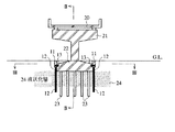
図1は橋脚基礎に適用した本発明の基礎補強構造を示す断面図であり、図2は図1における一点鎖線II−IIに沿った縦断面図であり、図3は図1における一点鎖線III−IIIに沿った平断面図であり、図4は図1乃至図3とは異なる実施例を示す平断面図である。
図1乃至図3に示したように、本発明の基礎補強構造を適用する橋脚21は、複数の杭23とその上に一体に形成されたフーチング22とからなる基礎によって支持され、上部に高架道路20を支持している。このような高架道路のフーチング22は所定の方向に所定の間隔で構築されており、例えば、河川を渡る高架道路は多くの場合に河川に直交するような配置で設けられており、また港湾や海岸に延びる高架道路には海に対してほぼ垂直な配置で設けられたものもある。
【0018】
かような橋脚21に、本発明では主要部として、連続する地中壁12と、地中壁12をフーチング22に固定する固定手段としてのアンカーボルト13とを設けることにより、基礎構造の補強を図るものである。
【0019】
ここで、前記地中壁12は、複数の鋼矢板(図示せず)をその継手で連結して形成し、図3に示したように、橋脚21のフーチング22を対向する二方向から挟むと共に隣合うフーチング22間の地盤を囲んで連続するように配置する。この時、鋼矢板は図1に示したように地中壁12が液状化層24を貫通する程度の長さのものを使用する。
【0020】
また地中壁12の上端には、隣合う各フーチング22,22間を連結する連結補強部材として、鉄筋コンクリートによる地中梁11を一体に形成する。なお、この地中梁11には、引張応力が作用しても破断しないように、軸方向に構造的に連続するように鉄筋を配置する。
【0021】
さらに各フーチング22,22間と地中壁12,12に囲まれた地盤には、セメントグラウト等のセメント系固化剤を注入して地盤改良をしても良い。更にまた、地中壁12,12間の地盤あるいは地中壁12やフーチング22の側方の地盤には、先端が液状化層に達するパイプ(図示せず)を設け、地下水を抜くようにしても良い。
【0022】
なお連結補強部材としては上記地中梁11に替えて、図4に示したように、ストランド15を各フーチング22,22間に張設しても良い。この時、ストランド15の配設位置は適宜定めることができるが、例えば、図4のように地中壁12から所定長離隔した位置に設けても良く、あるいは上記地中梁11と同様に地中壁12の上端に設けても良い。
【0023】
以上のような基礎補強構造を備えたフーチング22の周辺地盤で、液状化が生じて側方流動が起こった場合、地中壁12,12とフーチング22,22とで囲まれた地盤は、地中壁12で外周の表面層と絶縁されているため、図6に示したような斜めの亀裂が生じず、したがって地中壁12,12の外周の表面層のみが地中壁12,12に沿って側方流動の方向に動き、外周の表面層の荷重がフーチング22に伝達するのを防止することができる。
【0024】
また複数の鋼矢板により形成した地中壁12は、隣合う各フーチング22,22を連結し、かつ水平方向に所定以上の引張耐力を有するため、周辺地盤に側方流動化が生じて一部のフーチング22が水平方向に圧力を受けても、地中壁12を介して圧力を次々に隣のフーチング22に伝達するため、フーチング22や橋脚21の側方流動荷重に対する耐力を向上することができる。さらに、地中壁12の上端には地中梁11が設けられているため、各フーチング22,22間の水平圧力の伝達は、より一層効果的に行うことができる。
【0025】
さらにフーチング22,22間の地盤が地中壁12によって比較的強く拘束されているため、フーチング22,22間の地盤の液状化を抑制することができる。 更にまた、フーチング22,22間の地盤は地中壁12により囲まれているため、このフーチング22,22間に土砂硬化剤を注入すれば、効率良く地盤改良を行うことができる。
【0026】
【発明の効果】
本発明の基礎補強構造では、それぞれ隣合う基礎と地中壁とで囲まれた地盤は、地中壁で外周の表面層と絶縁されているため、周辺地盤で液状化が生じて側方流動が起こった場合でも、外周の表面層は地中壁に沿って側方流動の方向に動き、各基礎への伝達を防止できる。
【0027】
また本発明の基礎補強構造では、地中壁が隣合う各基礎を連結しているので、周辺地盤に側方流動化が生じて一部の基礎が水平方向に圧力を受けても、地中壁を介して圧力を次々に隣の基礎に伝達するため、基礎やその上の構造物は、側方流動荷重に対する耐力を向上することができる。
【0028】
さらに、各基礎間は連結補強部材によって連結されているため、各基礎間の水平圧力の伝達は、より一層効果的に行うことができる。
【0029】
更にまた、各基礎間の地盤が地中壁によって拘束されているため、各基礎間の地盤の液状化を抑制することができる。
【0030】
また各基礎間の地盤は地中壁により囲まれているため、この基礎間に土砂硬化剤を注入すれば、効率良く地盤改良を行うことができる。
【図面の簡単な説明】
【図1】本発明の構造物群の基礎補強構造を示す断面図である。
【図2】図1における一点鎖線II−IIに沿った縦断面図である。
【図3】図1における一点鎖線III−IIIに沿った平断面図である。
【図4】図1乃至図3とは異なる実施例を示す平断面図である。
【図5】 (a)は従来例を示す側断面図であり、(b)は(a)の平断面図である。
【図6】従来の基礎群に側方流動荷重が作用する状態を示す概略平面図である。
【符号の説明】
11 鉄筋コンクリートによる地中梁(連結補強部材)
12 地中壁
13 アンカー(固定手段)
15 ストランド(連結補強部材)
21 橋脚(構造物)
22 フーチング(基礎)[0001]
BACKGROUND OF THE INVENTION
The present invention relates to a foundation reinforcing structure for a plurality of existing structure groups or new structure groups constructed in a predetermined direction at predetermined intervals.
[0002]
[Prior art]
The ground near a river or the sea may include a non-liquefied layer, a liquefied layer located thereon, and a surface layer located on the liquefied layer. In such a ground, the non-liquefied layer is inclined obliquely downward toward the river or the sea in many cases, so when a liquefaction phenomenon occurs, the liquefied sediment will flow into the river according to the inclination of the non-liquefied layer. Or may flow toward the sea. The liquefied soil also flows when the revetment or quay breaks during an earthquake and changes its shape, or when the surface ground of the liquefied layer is inclined.
[0003]
On the other hand, some bridge piers such as viaducts, warehouse groups or apartment houses have a plurality of foundations constructed at predetermined intervals in a substantially constant direction. For example, as shown in the schematic plan view of FIG. 6, some of the
[0004]
Conventionally, as a general countermeasure against ground liquefaction, there is a construction method that builds a continuous underground wall that surrounds the entire circumference of each foundation of the structure, or an existing pile as shown in Figs. 5 (a) and 5 (b). An additional pile construction method has been proposed in which an
[0005]
[Problems to be solved by the invention]
However, as shown in FIG. 6, when the ground is liquefied around the
Transmission of an excessive load on the surface layer as described above cannot be prevented by a conventional method of reinforcing a simple foundation, and may cause the
[0006]
The present invention has been made to solve the above-mentioned problems, and its purpose is that even if a lateral fluidization phenomenon occurs in the ground, the flow load from the liquefied layer and the load on the surface layer over a wide range in the oblique direction. It is intended to provide a foundation reinforcing structure for a group of structures that prevents the foundation and its superstructure from collapsing.
[0007]
Another object of the present invention is to provide a foundation reinforcing structure for a group of structures that can relatively strongly restrain the ground between the foundations and thereby suppress liquefaction between the foundations.
[0008]
Another object of the present invention is to provide a foundation reinforcing structure for a group of structures that can improve the horizontal strength of each foundation.
[0009]
Furthermore, another object of the present invention is to provide a foundation reinforcing structure for a group of structures that can efficiently harden the sand between the foundations when the earth and sand hardening agent is injected to improve the ground between the foundations. is there.
[0010]
[Means for Solving the Problems]
The present invention has been made in view of the above-mentioned object, and the gist thereof is a plurality of structures such as a plurality of bridge piers, warehouse groups, or apartment houses that are constructed so as to be arranged in a predetermined direction at predetermined intervals. in the basic, viewed sandwiched from two directions opposite to each foundation and adjacent said building the ground the circumference unnecessarily continuous underground wall between the foundation fixed to the each foundation by fixing means該地the wall In addition , the present invention provides a foundation reinforcing structure for a group of structures, characterized in that a connection reinforcing member for connecting the foundations is provided .
[0011]
In the foundation reinforcing structure of the structure group of the present invention, examples of the plurality of structures constructed at predetermined intervals in a predetermined direction include a bridge pier such as a viaduct, a warehouse group, or an apartment house group. Are constructed approximately at regular intervals or at predetermined different intervals, and are arranged in a straight line in a certain direction, or are arranged in a certain direction while drawing a gentle curve.
[0012]
In the present invention, when the ground around the foundation is liquefied and lateral flow occurs, the underground wall in the present invention is the laterally flowing earth and sand and the surface layer thereon, and the earth and sand between each foundation and the surface thereon. Any wall body that can insulate the layer, for example, a continuous underground wall made of sheet pile, a column wall made of steel reinforced underground columns made of soil mortar, or a continuous underground wall made of cast-in-place reinforced concrete Etc., and preferably the underground wall is constructed by a sheet pile. The underground wall by the sheet pile has an advantage that it can be economically constructed by a compact construction machine that does not take a work space compared to other underground walls.
Here, the material of the sheet pile can be selected as appropriate, and can be appropriately selected from, for example, a wood sheet pile, a reinforced concrete sheet pile, a prestressed concrete sheet pile, a pressurized concrete sheet pile, a steel sheet pile, and preferably continuous with a steel sheet pile. To build underground walls. In addition, when a steel sheet pile is used as the sheet pile, there is an advantage that a tensile force can be transmitted by the joint and excess pore water pressure generated by liquefaction can be cut off.
[0013]
In the present invention, as a fixing means for fixing the underground wall to each foundation, for example, an anchor bolt or a reinforcing bar can be used.
[0014]
In the present invention, a connecting reinforcing member that connects these foundations may be provided between the foundations. The connecting reinforcing members connect adjacent foundations and apply horizontal forces acting on the foundations to the adjacent foundations. It only needs to be able to communicate to. As such a connection reinforcing member, for example, a wire rope, a strand, a steel frame, a reinforcing bar, a reinforced concrete, or a tie rod can be used.
[0015]
Further, in the present invention, earth and sand hardening agent may be injected into the ground between the predetermined foundations surrounded by the underground wall, and this earth and sand hardening agent forms a water stop film on the earth and sand to improve the strength of soil quality. However, any material can be used as long as the ground is not easily liquefied during an earthquake. As such a soil hardening agent, for example, a cement-based solidifying agent such as cement grout, a water glass-based solidifying agent, or a resin-based solidifying agent such as urea or acrylamide can be used.
[0016]
Further, in the present invention, one or more groundwater draining means may be provided on the underground wall, and the groundwater draining means is at least water in the aquifer when the water pressure of the aquifer increases due to vibration in the ground. Any means can be used as long as it can be eliminated. As such a groundwater draining means, for example, a columnar body, a perforated pipe, a synthetic resin pipe, or a screen pipe formed in the ground by sand or gravel can be used.
[0017]
【Example】
Embodiments of the present invention will be described below with reference to the accompanying drawings.
1 is a cross-sectional view showing a foundation reinforcing structure of the present invention applied to a pier foundation, FIG. 2 is a vertical cross-sectional view taken along the alternate long and short dash line II-II in FIG. 1, and FIG. 3 is an alternate long and short dash line III in FIG. FIG. 4 is a plan sectional view taken along line -III, and FIG. 4 is a plan sectional view showing an embodiment different from those shown in FIGS.
As shown in FIGS. 1 to 3, the
[0018]
By providing the
[0019]
Here, the
[0020]
Further, an
[0021]
Furthermore, the ground may be improved by injecting a cement-based solidifying agent such as cement grout into the ground surrounded by the
[0022]
As the connecting reinforcing member, the
[0023]
When liquefaction occurs and lateral flow occurs in the surrounding ground of the
[0024]
In addition, the
[0025]
Furthermore, since the ground between the
[0026]
【The invention's effect】
In the foundation reinforcing structure of the present invention, the ground surrounded by the adjacent foundation and the underground wall is insulated from the outer surface layer by the underground wall. Even if this occurs, the outer surface layer moves in the direction of lateral flow along the underground wall, preventing transmission to each foundation.
[0027]
Further, in the foundation reinforcing structure of the present invention, the underground walls connect adjacent foundations, so that even if some foundations are subjected to pressure in the horizontal direction due to lateral fluidization in the surrounding ground, Since the pressure is transmitted to the next foundation one after another through the wall, the foundation and the structure on the foundation can improve the resistance to the lateral flow load.
[0028]
Furthermore, since the foundations are connected by the connection reinforcing member, the horizontal pressure between the foundations can be transmitted more effectively.
[0029]
Furthermore, since the ground between each foundation is restrained by the underground wall, liquefaction of the ground between each foundation can be suppressed.
[0030]
Moreover, since the ground between each foundation is surrounded by the underground wall, if the earth and sand hardening agent is inject | poured between this foundation, ground improvement can be performed efficiently.
[Brief description of the drawings]
FIG. 1 is a cross-sectional view showing a basic reinforcing structure of a group of structures according to the present invention.
FIG. 2 is a longitudinal sectional view taken along one-dot chain line II-II in FIG.
3 is a plan sectional view taken along one-dot chain line III-III in FIG.
4 is a plan sectional view showing an embodiment different from those shown in FIGS. 1 to 3; FIG.
5A is a side sectional view showing a conventional example, and FIG. 5B is a plan sectional view of FIG. 5A.
FIG. 6 is a schematic plan view showing a state in which a lateral flow load acts on a conventional foundation group.
[Explanation of symbols]
11 Reinforced concrete underground beam (reinforcement member)
12
15 Strand (Connecting reinforcement member)
21 Pier (structure)
22 Footing (basic)
Claims (3)
前記各基礎を対向する二方向から挟み、且つ隣合う前記各基礎間の地盤を囲むように連続する地中壁を構築し、該地中壁を固定手段で前記各基礎に固定し、前記各基礎間を連結する連結補強部材を設けたことを特徴とする構造物群の基礎補強構造。 On the basis of a plurality of structures such as a plurality of piers, warehouse groups or apartment houses, each constructed to be arranged in a certain direction at predetermined intervals,
The look clamping the two directions opposite to each foundation, build and adjacent the ground the circumference unnecessarily continuous underground wall between the foundation, is fixed to the each foundation by fixing means該地in the wall, each A foundation reinforcing structure for a group of structures, characterized in that a connecting reinforcing member for connecting the foundations is provided .
Priority Applications (1)
| Application Number | Priority Date | Filing Date | Title |
|---|---|---|---|
| JP34549095A JP3687805B2 (en) | 1995-12-08 | 1995-12-08 | Foundation reinforcement structure of structures |
Applications Claiming Priority (1)
| Application Number | Priority Date | Filing Date | Title |
|---|---|---|---|
| JP34549095A JP3687805B2 (en) | 1995-12-08 | 1995-12-08 | Foundation reinforcement structure of structures |
Publications (2)
| Publication Number | Publication Date |
|---|---|
| JPH09158212A JPH09158212A (en) | 1997-06-17 |
| JP3687805B2 true JP3687805B2 (en) | 2005-08-24 |
Family
ID=18376942
Family Applications (1)
| Application Number | Title | Priority Date | Filing Date |
|---|---|---|---|
| JP34549095A Expired - Fee Related JP3687805B2 (en) | 1995-12-08 | 1995-12-08 | Foundation reinforcement structure of structures |
Country Status (1)
| Country | Link |
|---|---|
| JP (1) | JP3687805B2 (en) |
Families Citing this family (17)
| Publication number | Priority date | Publication date | Assignee | Title |
|---|---|---|---|---|
| JP2001288758A (en) * | 2000-04-04 | 2001-10-19 | Nishimatsu Constr Co Ltd | Footing earthquake resistant construction and footing earthquake resistance reinforcing method |
| JP3515567B1 (en) * | 2002-10-02 | 2004-04-05 | 幸武 塩井 | Seismic reinforcement structure of structures |
| JP4121411B2 (en) * | 2003-03-31 | 2008-07-23 | 財団法人鉄道総合技術研究所 | Non-occlusive reinforcement structure |
| JP4589849B2 (en) * | 2005-09-08 | 2010-12-01 | 株式会社竹中工務店 | Liquefaction prevention method for existing building foundations |
| JP4724680B2 (en) * | 2007-03-08 | 2011-07-13 | 新日本製鐵株式会社 | Column base structure |
| JP4960731B2 (en) * | 2007-03-13 | 2012-06-27 | 株式会社大林組 | Seismic reinforcement structure for viaduct |
| JP4943190B2 (en) * | 2007-03-13 | 2012-05-30 | 株式会社大林組 | Seismic reinforcement structure for viaduct |
| JP2008303598A (en) * | 2007-06-07 | 2008-12-18 | Nippon Steel Corp | Column base structure in multi-column bridge pier |
| JP5147361B2 (en) * | 2007-11-06 | 2013-02-20 | 株式会社不動テトラ | Repair and reinforcement structure for floating structures |
| JP2013155559A (en) * | 2012-01-31 | 2013-08-15 | Shimizu Corp | Liquefaction damage reducing structure for construction |
| JP5976373B2 (en) * | 2012-04-20 | 2016-08-23 | 鹿島建設株式会社 | Pile foundation reinforcement structure and reinforcement method |
| CN107165058B (en) * | 2017-05-08 | 2019-05-21 | 中铁上海设计院集团有限公司 | One kind being used for existing operation Bridge pier reinforcement means |
| JP6869825B2 (en) * | 2017-06-28 | 2021-05-12 | 鹿島建設株式会社 | Pier foundation structure |
| JP2019073886A (en) * | 2017-10-16 | 2019-05-16 | 東日本旅客鉄道株式会社 | Vibration displacement suppressing structure of structure group |
| JP2019073885A (en) * | 2017-10-16 | 2019-05-16 | 東日本旅客鉄道株式会社 | Vibration displacement suppressing structure of structure group |
| CN110904865A (en) * | 2019-12-13 | 2020-03-24 | 广州市第三市政工程有限公司 | Bridge reinforcing method and bridge reinforced by applying same |
| CN111254843A (en) * | 2020-01-21 | 2020-06-09 | 南京铁道职业技术学院 | Bridge pile foundation uplifting structure and construction method thereof |
Family Cites Families (3)
| Publication number | Priority date | Publication date | Assignee | Title |
|---|---|---|---|---|
| JPH03202511A (en) * | 1989-12-28 | 1991-09-04 | Shimizu Corp | Liquefaction-proof construction |
| JPH0645943B2 (en) * | 1990-03-26 | 1994-06-15 | 住友金属工業株式会社 | Liquefaction countermeasure construction method for buried structures |
| JP2751652B2 (en) * | 1991-03-29 | 1998-05-18 | 住友金属工業株式会社 | Liquefaction prevention structure for lifeline structures |
-
1995
- 1995-12-08 JP JP34549095A patent/JP3687805B2/en not_active Expired - Fee Related
Also Published As
| Publication number | Publication date |
|---|---|
| JPH09158212A (en) | 1997-06-17 |
Similar Documents
| Publication | Publication Date | Title |
|---|---|---|
| JP3687805B2 (en) | Foundation reinforcement structure of structures | |
| CN110541354B (en) | Single-section prefabricated anti-seismic pier and construction method thereof | |
| CN106758786B (en) | A kind of prefabricated assembled concrete-filled double skin steel tube lattice bridge pier | |
| JPH07300820A (en) | Close contact type protective construction method against falling rock and rope/net anchor structure thereof | |
| KR100745401B1 (en) | Non-support, non-expension joint and non-abutment slab bridge having synchronized supporting post system, and installing method thereof | |
| KR100382877B1 (en) | Pier revolution apparatus and T-type pier construction method using the same | |
| CN211171579U (en) | Take seamless antidetonation abutment of disconnect-type strap | |
| KR20120100052A (en) | Bridge leg correcting method using oil compressure jack and broken parts compensation structure | |
| US11629473B2 (en) | Multiple friction joint pile system | |
| JP2008031754A (en) | Foundation ground reinforcing structure and foundation ground reinforcing method | |
| KR101020217B1 (en) | rock construction structure of using anchor and method thereof | |
| KR100493516B1 (en) | Micro pile and assembly foundation reinforcement structure member and its method for pier | |
| CN104929101A (en) | Bottom expanding-multisection side expanding anti-pull prestressed anchoring gravel pile and construction method | |
| KR102463636B1 (en) | External Reinforcement Structure of Head Cutting PC Pile | |
| JP3678290B2 (en) | High earthquake resistance foundation | |
| JP7308491B2 (en) | Double sheet pile type water structure and its construction method | |
| KR102521965B1 (en) | Bridge having reinforced structure for transverse direction and point part | |
| CN218911099U (en) | Pile plate elastic connection structure | |
| KR200241295Y1 (en) | Pier revolution apparatus and T-type pier construction structure using the same | |
| JP7019905B2 (en) | Pile foundation structure and reinforcement method for existing piles | |
| KR102671025B1 (en) | Pier and Construction Method using Centrifugal High-Strength PHC Piles | |
| KR101274944B1 (en) | Column structure reinforcing method for bending and ductility by partial reinforcing | |
| CN115478548B (en) | Expansion soil cutting side slope expansion-reducing anti-seismic disaster-preventing combined retaining structure and construction method | |
| JP2019044473A (en) | Quay wall or revetment structure, and construction method of the same | |
| KR100622448B1 (en) | Steel sheet pile pier |
Legal Events
| Date | Code | Title | Description |
|---|---|---|---|
| A977 | Report on retrieval |
Free format text: JAPANESE INTERMEDIATE CODE: A971007 Effective date: 20041217 |
|
| A131 | Notification of reasons for refusal |
Free format text: JAPANESE INTERMEDIATE CODE: A131 Effective date: 20050201 |
|
| A521 | Written amendment |
Free format text: JAPANESE INTERMEDIATE CODE: A523 Effective date: 20050331 |
|
| TRDD | Decision of grant or rejection written | ||
| A01 | Written decision to grant a patent or to grant a registration (utility model) |
Free format text: JAPANESE INTERMEDIATE CODE: A01 Effective date: 20050510 |
|
| A61 | First payment of annual fees (during grant procedure) |
Free format text: JAPANESE INTERMEDIATE CODE: A61 Effective date: 20050602 |
|
| R150 | Certificate of patent or registration of utility model |
Free format text: JAPANESE INTERMEDIATE CODE: R150 |
|
| FPAY | Renewal fee payment (event date is renewal date of database) |
Free format text: PAYMENT UNTIL: 20080617 Year of fee payment: 3 |
|
| FPAY | Renewal fee payment (event date is renewal date of database) |
Free format text: PAYMENT UNTIL: 20110617 Year of fee payment: 6 |
|
| LAPS | Cancellation because of no payment of annual fees |