JP3686313B2 - Blood vessel cannula - Google Patents
Blood vessel cannula Download PDFInfo
- Publication number
- JP3686313B2 JP3686313B2 JP2000209893A JP2000209893A JP3686313B2 JP 3686313 B2 JP3686313 B2 JP 3686313B2 JP 2000209893 A JP2000209893 A JP 2000209893A JP 2000209893 A JP2000209893 A JP 2000209893A JP 3686313 B2 JP3686313 B2 JP 3686313B2
- Authority
- JP
- Japan
- Prior art keywords
- blood vessel
- branch pipe
- cannula
- tube
- catheter
- Prior art date
- Legal status (The legal status is an assumption and is not a legal conclusion. Google has not performed a legal analysis and makes no representation as to the accuracy of the status listed.)
- Expired - Fee Related
Links
Images


Description
【0001】
【発明の属する技術分野】
この発明は、心臓もしくは大動脈手術の際に血管内に挿入し、血液を体外循環回路に送り、或いは体外循環回路から血管に戻すとともに、必要に応じて挿入する血管カテーテル又はガイドワイヤを血管にスムーズに挿入するための補助として用いる血管挿入用カニューレに関するものである。
【0002】
【従来の技術】
従来のこの種のカニューレとして、実開平6−21648号公報に記載のものが知られている。このカニューレは長さ方向に貫通したメインルーメンを有し、後端開口部にコネクタを設けた本体チューブと、該本体チューブの後端部近傍に後端側に傾斜して設けられ、前記メインルーメンと連通したガイドワイヤを挿通するための枝管からなるカテーテルチューブであって、該枝管は本体チューブに対して5°〜20°の角度をなすとともに、その後端部近傍にクランプを付設したものである。
【0003】
しかしながら、前記従来のカニューレは、本体チューブの全体が同一径の太さのものからなっているため、挿入する血管を切開する長さが必然的に長くなってしまい、切開長を可及的に短くして傷を小さくすることの医学上の要請に応えられないという問題がある。また、本体チューブ及び枝管の全体が軟質樹脂からなっているため、ガイドワイヤだけの挿入ならまだそうでもないが、挿入抵抗が比較的大きい例えば血管カテーテルを挿入する場合には本体チューブ及び枝管が屈曲し易く、挿入しにくいという問題もある。
【0004】
【発明が解決しようとする課題】
そこでこの発明は、前記のような従来の問題点を解決し、挿入する血管の切開長を可及的に短くすることができるとともに、挿入抵抗が比較的大きい血管カテーテル等を挿入する場合でも屈曲しにくくて力を入れ易い血管挿入用カニューレを提供することを目的とする。
【0005】
【課題を解決するための手段】
前記の目的を達成するため、図面に示すように、請求項1の発明は、血管に挿入して、血液を体外循環回路に送り、或いは体外循環回路から血管に戻すとともに、必要に応じて挿入する血管カテーテル又はガイドワイヤを血管にスムーズに挿入するための補助として用いるカニューレ1であって、軟質樹脂で成形され先端に向かって先細のテーパ状になっている挿入側のチューブ前部2と、硬質樹脂で成形され途中から後部側へ向け所定角度で傾斜して分岐した枝管4を有する連結用チューブ中間部3と、軟質樹脂で成形されているチューブ後部5とが、ほぼ直線状をなすように一体に連結されているとともに、枝管4の後端開口部とチューブ後部5の後端開口部にそれぞれ疎水性フィルター 10 , 11 が着脱可能に取り付けられていることを特徴とする。
【0006】
請求項2の発明は、請求項1において、枝管4の分岐角度が15°〜25°の範囲であることを特徴とする。請求項3の発明は、請求項1又は2において、枝管4にキャップ7付きの空気抜き管6が分岐して設けられていることを特徴とする。請求項4の発明は、請求項1ないし3において、後端開口部から疎水性フィルター10が取り外された枝管4に血管カテーテル16又はガイドワイヤ挿入固定用シールコネクタ15が着脱可能に取り付けられるようになっていることを特徴とする。
【0007】
請求項5の発明は、請求項4において、シールコネクタ15は、血管カテーテル16又はガイドワイヤを挿通可能な径の内孔17が形成されているとともに、周壁に鍵状の切り込み溝19が形成されて枝管4に嵌合される両端開口の中空筒状コネクタ本体20と、このコネクタ本体に螺合して取り付けられ、血管カテーテル又はガイドワイヤを挿通可能な径の内孔21が形成されているねじ部材23と、このねじ部材とコネクタ本体との間及びコネクタ本体と枝管との間に配置されるシール部材24,25とを具え、取付けに際して切り込み溝19が枝管4に設けた係止ピン8に係止するようになっていることを特徴とする。
【0008】
【発明の実施の形態】
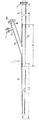
この発明の一実施の形態の血管挿入用カニューレを図面を参照して説明する。図1は血管挿入用カニューレの長さ方向の一部を省略して示す全体の縦断正面図、図2はシールコネクタの斜視図、図3はシールコネクタが枝管の後部に取り付けられた状態の拡大縦断正面図、図4はシールコネクタを介して血管挿入用カニューレに血管カテーテルを取り付けた状態の、その長さ方向の一部を省略して示す全体の正面図である。
【0009】
1はカニューレで、軟質樹脂で成形され先端に向かって先細のテーパ状になっている挿入側のチューブ前部2と、硬質樹脂で成形され途中から後部側へ向け所定角度で傾斜して分岐した枝管4を一体に有する連結用チューブ中間部3と、軟質樹脂で成形されているチューブ後部5とを具え、これらがその隣接端部を嵌合したうえ接着剤等によりほぼ直線状をなすように一体に連結されている。
【0010】
チューブ前部2は全長L1が約20cmの、例えば軟質塩化ビニル樹脂、ポリウレタン、シリコーンゴム等の医療器具として適した材質の樹脂からなり、後端開口部の内外径がそれぞれ例えば8mm,12mmとなっているとともに、先端に行くに従って徐々に細く先端開口部の内外径がそれぞれ例えば6mm,7mmとなっており、先端面が斜めにカットされている。チューブ中間部3は全長L2が約15cmの、例えばポリカーボン、ポリサルフォン等の硬質の材料樹脂からなり、内外径が枝管4を含めそれぞれ例えば7mm,12mmとなっている。枝管4の分岐角度は15°〜25°、好ましくは18°〜22°の範囲となっている。枝管4には空気抜き管6が分岐して設けられ、該管にはキャップ7が取り付けられている。8は空気抜き管6より後方の枝管4の外面にそれぞれ反対側に位置するように設けられている1対の係止ピンである。チューブ後部5はチューブ前部2と同じ材質からなっており、全長L3が約20cm、内外径がそれぞれ例えば8mm,12mmとなっている。枝管4の後端開口部とチューブ後部5の後端開口部にはそれぞれ疎水性フィルター10,11が着脱可能に取り付けられている。
【0011】
図2で15は血管カテーテル又はガイドワイヤ挿入固定用シールコネクタで、図3にも詳示するように血管カテーテル16又は図示省略のガイドワイヤを挿通可能な径の内孔17が内向きフランジ部18の内側に形成されているとともに、相対向する周壁に鍵状の切り込み溝19が形成されて枝管4に嵌合される両端開口の中空筒状コネクタ本体20と、このコネクタ本体に螺合して取り付けられ、血管カテーテル16を挿通可能な径の内孔21が筒状部22の内側に形成されているねじ部材23と、このねじ部材とコネクタ本体20との間に配置され、血管カテーテル16と枝管4との間をシールするシール部材24,25とからなっており、その切り込み溝19を係止ピン8に係止させて着脱可能に取り付けられるようになっている。シール部材24は実施の形態ではゴムパッキンからなり、その中央部に明いた穴26は常態では血管カテーテル16の外径とほぼ等しいか、僅かに小となっていて、ねじ部材23による締め付けによりねじ部材の先端面と内向きフランジ部17の間で潰されて穴26側の縁部がさらに血管カテーテル16の外面に接するようになってシールする。シール部材25は実施の形態ではOリングからなっている。鍵状の切り込み溝19はこの実施の形態ではコネクタ本体20の軸方向に延びる軸方向溝部19aと、該溝部の奥からコネクタ本体20の径方向に延びる径方向溝部19bとからなる、L字状溝からなっている。
【0012】
血管カテーテル16は図4に示すような構成となっており、前後端が開口したメインルーメンを有するカテーテル本体31の先端部にバルーン32が設けられ、後端開口部にキャップ33が設けられているとともに、その近傍にバルーン32用のルアー34付き分岐管35が設けられている。36は別の分岐管で、その先端ルアー37には図示しない圧力センサが取り付けられている。この実施の形態では前記のようにシールコネクタ15で固定するものとして血管カテーテル16を示したが、これに限らずガイドワイヤでもよいことは勿論である。
【0013】
使用に際しては、まず血管(通常、大腿動脈)を剥離・露出した後に、小切開して、チューブ前部2から血管内に約5cm挿入する。このときカニューレ1内に血液が流れ込んでくるが、カニューレ1内の空気は疎水性フィルタ10,11を通過して外に逃げ、血液でカニューレ1が満たされるのを邪魔しないが、疎水性フィルタ10,11は血液を通さないので、満たされるタイミングを図ってクランプで止めるといった必要がなくなる。ついで、チューブ後部5を図示しないクランプなどによってクランプしてから、疎水性フィルタ11を取り外し、チューブ後部5の後端開口部に図示しない体外循環回路を接続する。
【0014】
次に、血管カテーテル16に付いているシールコネクタ15のねじ部材23が緩んでいることを確認し、さもなくばねじ部材23を緩め、血管カテーテル16のできるだけ先端に位置させてからねじ部材23を締める。このときねじ部材23が緩んでいてもシール部材24の穴26は常態では血管カテーテル16の外径とほぼ等しいか、僅かに小となっているため血管カテーテルとシール部材24との隙間から血液が漏れることなく、ねじ部材23を締めるとシール部材24は潰されて内側に押し出されるようになり(潰される力を逃がすように働く)、ことによって締め付け、血管カテーテル16が固定される。
【0015】
そして、枝管4に付いている疎水性フィルタ10を外し、シールコネクタ15の切り込み溝19に係止ピン8を沿わせながら血管カテーテル16を挿入し、係止ピン8が切り込み溝19の軸方向溝部19aの一番奥まで達したら右に回し、さらに径方向溝部19bの一番奥に至らしめて(図4参照)シールコネクタ15をロックした後、空気抜き管6のキャップ7を開け、カテーテル挿入に伴って巻き込んだ空気を抜き、再びキャップ7をする。しかる後、シールコネクタ15のねじ部材23をやや緩め、血管カテーテル16をチューブ前部2を経由して血管の目的部位まで挿入し、ねじ部材23を締めて血管カテーテル16を固定し、血管カテーテル16のバルーン32を膨らませて、血管を閉鎖することや薬液注入など必要な措置を行う。
【0016】
前記に際し、ガイドワイヤを固定するには同様にしてガイドワイヤをチューブ前部2を経由して血管の目的部位まで挿入する。そして、ねじ部材23を締めてガイドワイヤを固定した後、カニューレ1を抜き、別のカニューレ又はカテーテルをそれに沿って挿入する措置を行う。
【0017】
【発明の効果】
請求項1ないし5の発明は前記のような構成からなるので、従来のカニューレではなかなかできなかった挿入する血管の切開長を可及的に短くすることができ、血管に挿入するための傷を小さくすることができる。また、挿入抵抗が比較的大きい血管カテーテル等を挿入する場合でも屈曲しにくく、挿入に際して力を入れ易い等、優れた効果がある。
【図面の簡単な説明】
【図1】この発明の一実施の形態の血管挿入用カニューレの長さ方向の一部を省略して示す全体の縦断正面図である。
【図2】シールコネクタの斜視図である。
【図3】シールコネクタが枝管の後部に取り付けられた状態の拡大縦断正面図である。
【図4】シールコネクタを介して血管挿入用カニューレに血管カテーテルを取り付けた状態の、その長さ方向の一部を省略して示す全体の正面図である。
【符号の説明】
1 カニューレ
2 チューブ前部
3 チューブ中間部
4 枝管
5 チューブ後部
6 空気抜き管
7 キャップ
8 係止ピン
10,11 疎水性フィルター
15 シールコネクタ
16 血管カテーテル
19 切り込み溝
20 コネクタ本体
23 ねじ部材
24,25 シール部材[0001]
BACKGROUND OF THE INVENTION
The present invention inserts a blood vessel into a blood vessel during heart or aortic surgery, sends blood to the extracorporeal circuit, or returns the blood from the extracorporeal circuit to the blood vessel, and smoothly inserts a blood vessel catheter or guide wire into the blood vessel as necessary. The present invention relates to a blood vessel cannula used as an auxiliary for insertion into a blood vessel.
[0002]
[Prior art]
As this type of cannula, one described in Japanese Utility Model Laid-Open No. 6-21648 is known. The cannula has a main lumen penetrating in the length direction, and is provided with a main body tube provided with a connector at a rear end opening portion, and provided at an inclination toward the rear end side in the vicinity of the rear end portion of the main body tube. Catheter tube comprising a branch tube for inserting a guide wire communicating with the tube, the branch tube having an angle of 5 ° to 20 ° with respect to the main body tube, and a clamp attached to the vicinity of the rear end thereof It is.
[0003]
However, in the conventional cannula, since the entire body tube is made of the same diameter, the length of incision of the blood vessel to be inserted is inevitably increased, and the incision length is made as long as possible. There is a problem that the medical request of shortening and reducing the wound cannot be met. In addition, since the entire body tube and branch pipe are made of a soft resin, it is not so much if only a guide wire is inserted, but the insertion resistance is relatively large, for example, when inserting a vascular catheter, the body tube and the branch pipe. Has a problem that it is easy to bend and difficult to insert.
[0004]
[Problems to be solved by the invention]
Therefore, the present invention solves the conventional problems as described above, can shorten the incision length of the blood vessel to be inserted as much as possible, and bends even when inserting a blood vessel catheter or the like having a relatively large insertion resistance. An object of the present invention is to provide a cannula for blood vessel insertion that is difficult to apply and easy to apply force.
[0005]
[Means for Solving the Problems]
In order to achieve the above object, as shown in the drawings, the invention of claim 1 is inserted into a blood vessel and sends blood to an extracorporeal circuit, or returns to the blood vessel from the extracorporeal circuit and is inserted as necessary. A cannula 1 used as an aid for smoothly inserting a vascular catheter or guide wire into a blood vessel, the tube front portion 2 on the insertion side formed of a soft resin and tapered toward the tip; The connecting tube intermediate portion 3 having the branch pipe 4 that is molded with a hard resin and is branched at a predetermined angle from the middle toward the rear side, and the tube rear portion 5 that is molded with a soft resin are substantially linear. JP that together are connected together, each of the rear end opening hydrophobic filter 10, 11 of the rear end opening and the tube rear 5 of the branch pipe 4 is mounted detachably to To.
[0006]
The invention of claim 2 is characterized in that, in claim 1, the branching angle of the branch pipe 4 is in the range of 15 ° to 25 °. A third aspect of the invention is characterized in that, in the first or second aspect , an air vent pipe 6 with a cap 7 is branched from the branch pipe 4. A fourth aspect of the present invention, in claims 1 to 3, so that the
[0007]
According to a fifth aspect of the present invention, in the
[0008]
DETAILED DESCRIPTION OF THE INVENTION
A blood vessel cannula according to an embodiment of the present invention will be described with reference to the drawings. FIG. 1 is a front view of the entire longitudinal section of the cannula for insertion of a blood vessel, with a part thereof omitted, FIG. 2 is a perspective view of the seal connector, and FIG. 3 is a state where the seal connector is attached to the rear part of the branch pipe FIG. 4 is an enlarged front view of the longitudinal section, and FIG. 4 is an overall front view showing a state in which a vascular catheter is attached to the cannula for blood vessel insertion via a seal connector, with a part of the length direction omitted.
[0009]
Reference numeral 1 denotes a cannula, a tube front portion 2 on the insertion side that is formed of a soft resin and has a tapered shape toward the tip, and is branched with a predetermined angle from the middle to the rear side formed of a hard resin. It has a connecting tube intermediate portion 3 integrally having a branch pipe 4 and a tube rear portion 5 formed of a soft resin so that these adjacent portions are fitted to each other and are substantially linear with an adhesive or the like. Are integrally connected to each other.
[0010]
The tube front part 2 is made of a resin having a total length L 1 of about 20 cm, for example, a material suitable for a medical instrument such as soft vinyl chloride resin, polyurethane, and silicone rubber. The inner and outer diameters of the rear end opening are 8 mm and 12 mm, respectively. In addition, the inner and outer diameters of the tip opening portion are, for example, 6 mm and 7 mm, which are gradually narrowed toward the tip, and the tip surface is cut obliquely. Tube intermediate section 3 is the overall length L 2 of about 15cm, for example polycarbon made of a material hard resin such as polysulfone, has inner and outer diameters respectively, for example 7mm including branch pipe 4, and 12 mm. The branch angle of the branch pipe 4 is in the range of 15 ° to 25 °, preferably 18 ° to 22 °. The branch pipe 4 is provided with a branching air vent pipe 6, and a cap 7 is attached to the pipe.
[0011]
In FIG. 2, 15 is a vascular catheter or guide wire insertion fixing seal connector. As shown in detail in FIG. 3, an
[0012]
The
[0013]
In use, first, the blood vessel (usually the femoral artery) is exfoliated and exposed, then a small incision is made, and about 5 cm is inserted into the blood vessel from the front part 2 of the tube. At this time, blood flows into the cannula 1, but the air in the cannula 1 passes through the hydrophobic filters 10 and 11 and escapes outside, and does not interfere with the filling of the cannula 1 with blood, but the hydrophobic filter 10 , 11 does not allow blood to pass, so there is no need to clamp it at the timing of filling. Next, after the tube rear portion 5 is clamped by a clamp or the like (not shown), the hydrophobic filter 11 is removed, and an extracorporeal circuit (not shown) is connected to the rear end opening of the tube rear portion 5.
[0014]
Next, it is confirmed that the
[0015]
Then, the hydrophobic filter 10 attached to the branch pipe 4 is removed, and the
[0016]
At this time, in order to fix the guide wire, the guide wire is similarly inserted through the tube front portion 2 to the target site of the blood vessel. Then, after tightening the
[0017]
【The invention's effect】
Since the inventions of claims 1 to 5 are configured as described above, the incision length of the blood vessel to be inserted, which could not be easily achieved by the conventional cannula, can be shortened as much as possible, and the wound for insertion into the blood vessel can be reduced. Can be small. In addition, even when a vascular catheter or the like having a relatively large insertion resistance is inserted, it is difficult to bend, and there is an excellent effect that a force can be easily applied during the insertion.
[Brief description of the drawings]
BRIEF DESCRIPTION OF DRAWINGS FIG. 1 is an overall longitudinal sectional front view of a blood vessel cannula according to an embodiment of the present invention, with a part in the length direction omitted.
FIG. 2 is a perspective view of a seal connector.
FIG. 3 is an enlarged longitudinal sectional front view of a state in which a seal connector is attached to a rear portion of a branch pipe.
FIG. 4 is an overall front view showing a state where a blood vessel catheter is attached to a blood vessel insertion cannula via a seal connector, with a part of the length direction omitted.
[Explanation of symbols]
DESCRIPTION OF SYMBOLS 1 Cannula 2 Tube front part 3 Tube intermediate part 4 Branch pipe 5 Tube rear part 6 Air vent pipe 7
10, 11 Hydrophobic filter
15 Seal connector
16 Vascular catheter
19 Notch groove
20 Connector body
23 Screw member
24, 25 Seal member
Claims (5)
Priority Applications (1)
| Application Number | Priority Date | Filing Date | Title |
|---|---|---|---|
| JP2000209893A JP3686313B2 (en) | 2000-07-11 | 2000-07-11 | Blood vessel cannula |
Applications Claiming Priority (1)
| Application Number | Priority Date | Filing Date | Title |
|---|---|---|---|
| JP2000209893A JP3686313B2 (en) | 2000-07-11 | 2000-07-11 | Blood vessel cannula |
Publications (2)
| Publication Number | Publication Date |
|---|---|
| JP2002017865A JP2002017865A (en) | 2002-01-22 |
| JP3686313B2 true JP3686313B2 (en) | 2005-08-24 |
Family
ID=18706240
Family Applications (1)
| Application Number | Title | Priority Date | Filing Date |
|---|---|---|---|
| JP2000209893A Expired - Fee Related JP3686313B2 (en) | 2000-07-11 | 2000-07-11 | Blood vessel cannula |
Country Status (1)
| Country | Link |
|---|---|
| JP (1) | JP3686313B2 (en) |
Families Citing this family (4)
| Publication number | Priority date | Publication date | Assignee | Title |
|---|---|---|---|---|
| JP4282567B2 (en) * | 2004-08-03 | 2009-06-24 | 嶌田 泰之 | Blood vessel and blood supply device using the same |
| KR101372682B1 (en) * | 2012-07-17 | 2014-03-11 | 인제대학교 산학협력단 | Multifunction cannula connecting apparatus for use in extracoporeal membrane oxygenation |
| EP3389756B1 (en) | 2015-12-18 | 2023-11-22 | Boston Scientific Scimed Inc. | Vascular introducer hubs for reducing blood leakage |
| WO2021215052A1 (en) * | 2020-04-23 | 2021-10-28 | 大塚テクノ株式会社 | Urinary catheter cap |
-
2000
- 2000-07-11 JP JP2000209893A patent/JP3686313B2/en not_active Expired - Fee Related
Also Published As
| Publication number | Publication date |
|---|---|
| JP2002017865A (en) | 2002-01-22 |
Similar Documents
| Publication | Publication Date | Title |
|---|---|---|
| US3805794A (en) | Antegrade-retrograde retention catheter | |
| JP3808806B2 (en) | Indwelling needle | |
| US6916051B2 (en) | Coupler for a flexible tube | |
| CA2545592C (en) | Luer with integrated clamp | |
| US20080300576A1 (en) | Catheter insertion assembly | |
| JP2005502387A5 (en) | ||
| JP4903603B2 (en) | Catheter fixture | |
| JPH10201850A (en) | Needle mechanism and valve mechanism for catheter | |
| US20140343512A1 (en) | Large bore sheath assembly | |
| JPH09508303A (en) | Reinforced microdialysis probe | |
| EP2436416B1 (en) | Catheter assembly including sealing member | |
| JP3686313B2 (en) | Blood vessel cannula | |
| JPH1033666A (en) | Bypass tube | |
| US11141194B2 (en) | Uterine hemostatic balloon unit | |
| JP2004512902A (en) | Adapter for PEG sonde | |
| US6979339B2 (en) | Medico-surgical instruments | |
| JP4900242B2 (en) | Aortic balloon pumping set | |
| KR20070048719A (en) | Flushing device and catheter set | |
| JP2006015058A (en) | Multilumen catheter | |
| JP4193469B2 (en) | Multi-lumen catheter | |
| JPH0515322Y2 (en) | ||
| KR200488954Y1 (en) | Drainage set of medical suction unit | |
| US20220087713A1 (en) | Convertible introducer sheath | |
| JP3489127B2 (en) | Balloon catheter set and balloon package used for it | |
| JPH04220268A (en) | Balloon catheter |
Legal Events
| Date | Code | Title | Description |
|---|---|---|---|
| A977 | Report on retrieval |
Free format text: JAPANESE INTERMEDIATE CODE: A971007 Effective date: 20041119 |
|
| A131 | Notification of reasons for refusal |
Free format text: JAPANESE INTERMEDIATE CODE: A131 Effective date: 20041207 |
|
| A521 | Written amendment |
Free format text: JAPANESE INTERMEDIATE CODE: A523 Effective date: 20050131 |
|
| TRDD | Decision of grant or rejection written | ||
| A01 | Written decision to grant a patent or to grant a registration (utility model) |
Free format text: JAPANESE INTERMEDIATE CODE: A01 Effective date: 20050506 |
|
| A61 | First payment of annual fees (during grant procedure) |
Free format text: JAPANESE INTERMEDIATE CODE: A61 Effective date: 20050602 |
|
| R150 | Certificate of patent or registration of utility model |
Free format text: JAPANESE INTERMEDIATE CODE: R150 Ref document number: 3686313 Country of ref document: JP Free format text: JAPANESE INTERMEDIATE CODE: R150 |
|
| FPAY | Renewal fee payment (event date is renewal date of database) |
Free format text: PAYMENT UNTIL: 20080610 Year of fee payment: 3 |
|
| FPAY | Renewal fee payment (event date is renewal date of database) |
Free format text: PAYMENT UNTIL: 20090610 Year of fee payment: 4 |
|
| R250 | Receipt of annual fees |
Free format text: JAPANESE INTERMEDIATE CODE: R250 |
|
| FPAY | Renewal fee payment (event date is renewal date of database) |
Free format text: PAYMENT UNTIL: 20090610 Year of fee payment: 4 |
|
| S111 | Request for change of ownership or part of ownership |
Free format text: JAPANESE INTERMEDIATE CODE: R313111 |
|
| S533 | Written request for registration of change of name |
Free format text: JAPANESE INTERMEDIATE CODE: R313533 |
|
| FPAY | Renewal fee payment (event date is renewal date of database) |
Free format text: PAYMENT UNTIL: 20090610 Year of fee payment: 4 |
|
| R350 | Written notification of registration of transfer |
Free format text: JAPANESE INTERMEDIATE CODE: R350 |
|
| FPAY | Renewal fee payment (event date is renewal date of database) |
Free format text: PAYMENT UNTIL: 20090610 Year of fee payment: 4 |
|
| FPAY | Renewal fee payment (event date is renewal date of database) |
Free format text: PAYMENT UNTIL: 20100610 Year of fee payment: 5 |
|
| R250 | Receipt of annual fees |
Free format text: JAPANESE INTERMEDIATE CODE: R250 |
|
| FPAY | Renewal fee payment (event date is renewal date of database) |
Free format text: PAYMENT UNTIL: 20110610 Year of fee payment: 6 |
|
| R250 | Receipt of annual fees |
Free format text: JAPANESE INTERMEDIATE CODE: R250 |
|
| FPAY | Renewal fee payment (event date is renewal date of database) |
Free format text: PAYMENT UNTIL: 20120610 Year of fee payment: 7 |
|
| R250 | Receipt of annual fees |
Free format text: JAPANESE INTERMEDIATE CODE: R250 |
|
| FPAY | Renewal fee payment (event date is renewal date of database) |
Free format text: PAYMENT UNTIL: 20130610 Year of fee payment: 8 |
|
| R250 | Receipt of annual fees |
Free format text: JAPANESE INTERMEDIATE CODE: R250 |
|
| R250 | Receipt of annual fees |
Free format text: JAPANESE INTERMEDIATE CODE: R250 |
|
| R250 | Receipt of annual fees |
Free format text: JAPANESE INTERMEDIATE CODE: R250 |
|
| R250 | Receipt of annual fees |
Free format text: JAPANESE INTERMEDIATE CODE: R250 |
|
| R250 | Receipt of annual fees |
Free format text: JAPANESE INTERMEDIATE CODE: R250 |
|
| R250 | Receipt of annual fees |
Free format text: JAPANESE INTERMEDIATE CODE: R250 |
|
| R250 | Receipt of annual fees |
Free format text: JAPANESE INTERMEDIATE CODE: R250 |
|
| R250 | Receipt of annual fees |
Free format text: JAPANESE INTERMEDIATE CODE: R250 |
|
| LAPS | Cancellation because of no payment of annual fees |