JP3685936B2 - Polymer electrolyte fuel cell system - Google Patents
Polymer electrolyte fuel cell system Download PDFInfo
- Publication number
- JP3685936B2 JP3685936B2 JP32714398A JP32714398A JP3685936B2 JP 3685936 B2 JP3685936 B2 JP 3685936B2 JP 32714398 A JP32714398 A JP 32714398A JP 32714398 A JP32714398 A JP 32714398A JP 3685936 B2 JP3685936 B2 JP 3685936B2
- Authority
- JP
- Japan
- Prior art keywords
- fuel cell
- air
- fuel
- polymer electrolyte
- water
- Prior art date
- Legal status (The legal status is an assumption and is not a legal conclusion. Google has not performed a legal analysis and makes no representation as to the accuracy of the status listed.)
- Expired - Lifetime
Links
Images

Classifications
-
- H—ELECTRICITY
- H01—ELECTRIC ELEMENTS
- H01M—PROCESSES OR MEANS, e.g. BATTERIES, FOR THE DIRECT CONVERSION OF CHEMICAL ENERGY INTO ELECTRICAL ENERGY
- H01M8/00—Fuel cells; Manufacture thereof
- H01M8/04—Auxiliary arrangements, e.g. for control of pressure or for circulation of fluids
- H01M8/04082—Arrangements for control of reactant parameters, e.g. pressure or concentration
- H01M8/04089—Arrangements for control of reactant parameters, e.g. pressure or concentration of gaseous reactants
- H01M8/04119—Arrangements for control of reactant parameters, e.g. pressure or concentration of gaseous reactants with simultaneous supply or evacuation of electrolyte; Humidifying or dehumidifying
-
- H—ELECTRICITY
- H01—ELECTRIC ELEMENTS
- H01M—PROCESSES OR MEANS, e.g. BATTERIES, FOR THE DIRECT CONVERSION OF CHEMICAL ENERGY INTO ELECTRICAL ENERGY
- H01M8/00—Fuel cells; Manufacture thereof
- H01M8/04—Auxiliary arrangements, e.g. for control of pressure or for circulation of fluids
- H01M8/04007—Auxiliary arrangements, e.g. for control of pressure or for circulation of fluids related to heat exchange
- H01M8/04029—Heat exchange using liquids
-
- H—ELECTRICITY
- H01—ELECTRIC ELEMENTS
- H01M—PROCESSES OR MEANS, e.g. BATTERIES, FOR THE DIRECT CONVERSION OF CHEMICAL ENERGY INTO ELECTRICAL ENERGY
- H01M8/00—Fuel cells; Manufacture thereof
- H01M8/04—Auxiliary arrangements, e.g. for control of pressure or for circulation of fluids
- H01M8/04007—Auxiliary arrangements, e.g. for control of pressure or for circulation of fluids related to heat exchange
- H01M8/04067—Heat exchange or temperature measuring elements, thermal insulation, e.g. heat pipes, heat pumps, fins
- H01M8/04074—Heat exchange unit structures specially adapted for fuel cell
-
- H—ELECTRICITY
- H01—ELECTRIC ELEMENTS
- H01M—PROCESSES OR MEANS, e.g. BATTERIES, FOR THE DIRECT CONVERSION OF CHEMICAL ENERGY INTO ELECTRICAL ENERGY
- H01M8/00—Fuel cells; Manufacture thereof
- H01M8/04—Auxiliary arrangements, e.g. for control of pressure or for circulation of fluids
- H01M8/04082—Arrangements for control of reactant parameters, e.g. pressure or concentration
- H01M8/04089—Arrangements for control of reactant parameters, e.g. pressure or concentration of gaseous reactants
- H01M8/04119—Arrangements for control of reactant parameters, e.g. pressure or concentration of gaseous reactants with simultaneous supply or evacuation of electrolyte; Humidifying or dehumidifying
- H01M8/04156—Arrangements for control of reactant parameters, e.g. pressure or concentration of gaseous reactants with simultaneous supply or evacuation of electrolyte; Humidifying or dehumidifying with product water removal
-
- Y—GENERAL TAGGING OF NEW TECHNOLOGICAL DEVELOPMENTS; GENERAL TAGGING OF CROSS-SECTIONAL TECHNOLOGIES SPANNING OVER SEVERAL SECTIONS OF THE IPC; TECHNICAL SUBJECTS COVERED BY FORMER USPC CROSS-REFERENCE ART COLLECTIONS [XRACs] AND DIGESTS
- Y02—TECHNOLOGIES OR APPLICATIONS FOR MITIGATION OR ADAPTATION AGAINST CLIMATE CHANGE
- Y02E—REDUCTION OF GREENHOUSE GAS [GHG] EMISSIONS, RELATED TO ENERGY GENERATION, TRANSMISSION OR DISTRIBUTION
- Y02E60/00—Enabling technologies; Technologies with a potential or indirect contribution to GHG emissions mitigation
- Y02E60/30—Hydrogen technology
- Y02E60/50—Fuel cells
Description
【0001】
【発明の属する技術分野】
本発明は、固体高分子型燃料電池を用いて発電を行う固体高分子型燃料電池システムに関するものである。
【0002】
【従来の技術】
以下に、従来の固体高分子型燃料電池システムについて説明する。
【0003】
図3に、従来の固体高分子型燃料電池システムを示す。水素生成装置2は天然ガスなどの原料を水蒸気改質し、水素リッチなガスを燃料電池1に供給する。水素生成装置2には、改質反応に必要な温度まで昇温させるバーナー3が設置されている。水素生成装置2の出口には、燃料電池1に供給する燃料ガスを加湿する燃料側加湿器4が設置されている。また、酸化剤としての空気は、空気供給装置5から供給され、空気側加湿器6により加湿される。燃料側加湿器4および空気側加湿器6は、燃料電池1の高分子膜の特性を保つためのものである。空気側加湿器6は、燃料電池1から排出される空気から水蒸気を回収する湿度交換型熱交換器で構成されている。燃料電池1から排出され空気側加湿器6で湿度を下げた空気は、空気側水回収器7で外気により冷却され、さらに除湿される。得られた凝縮水は水タンク8に蓄えられる。回収された水は、燃料側水ポンプ9により水素生成装置2および燃料側加湿器4に送られ、燃料改質および燃料側加湿に利用される。燃料電池1では、電気とともに熱が生じるために、冷却水を送る冷却用ポンプ10と、発生した熱を外部へ放出する冷却用放熱器11を備えている。
【0004】
水素生成装置2内では、天然ガスから水素リッチなガスを生成する改質反応を促進するために、温度が700℃程度になるようにバーナー3で加熱する。この改質反応には水蒸気が必要となるため、燃料側水ポンプ9より水が供給されている。水素生成装置2を出た燃料ガスは、燃料側加湿器4で加湿され、燃料電池1に送り込まれる。燃料電池1より排出される発電に用いられなかった燃料ガスは、バーナー3に送られ燃焼に利用される。なお、起動時は改質に必要な温度に達しないために、充分に水素に変換することができない。このとき改質ガスには一酸化炭素を多く含んでいる。一酸化炭素は燃料電池1の特性を大きく低下させることから、燃料電池1にガスを流すことができない。したがって、改質ガスを直接バーナー3に供給するバイパス回路12が設けられている。
【0005】
【発明が解決しようとする課題】
しかしながら、上記従来例のような燃料電池システムにおいて発電を行う際に、燃料電池1において大量の水蒸気が生成し、これが空気側加湿器6や空気側流路で結露し、空気側圧力および空気流量が変動し、電池特性が低下する課題を生じた。
【0007】
本発明は、上述したこのような従来の固体高分子型燃料電池システムが有する課題を考慮して、高効率で安定した運転を確保することができる固体高分子型燃料電池システムを提供することを目的とするものである。
【0008】
【課題を解決するための手段】
本発明(請求項1に記載の本発明に対応)は、少なくとも、
水素を含む燃料ガスと空気を用いて発電を行う固体高分子型の燃料電池と、
前記燃料電池への供給空気と前記燃料電池からの排出空気との間の熱交換を行うとともに、前記供給空気の加湿および前記排出空気の除湿を行う湿度交換型熱交換器と、
前記湿度交換型熱交換器より排出される空気に含まれる水蒸気を凝縮して回収する空気側水回収器とを備え、
前記燃料電池、前記湿度交換型熱交換器、及び前記空気側水回収器は、最上部に前記燃料電池が位置し、前記燃料電池の下方に前記湿度交換型熱交換器が位置し、前記湿度交換型熱交換器の下方に前記空気側水回収器が位置することを特徴とする固体高分子型燃料電池システムである。
【0009】
本発明に関連する発明は、少なくとも、燃料ガスと空気を用いて発電を行う固体高分子型の燃料電池と、原料を水蒸気改質して水素リッチな改質ガスを生成する水素生成装置と、前記燃料電池より排出される燃料ガスに含まれる水蒸気を凝縮して回収する燃料側水回収器と、前記水素生成装置の出口と前記燃料側水回収器の入口を結ぶバイパス管と、起動時には、改質ガスを前記バイパス管へ導き、通常運転時には改質ガスを前記燃料電池へ導く切り替え機構とを、備えたことを特徴とする固体高分子型燃料電池システムである。
【0010】
【発明の実施の形態】
以下に、本発明の実施の形態を図面を参照して説明する。
【0011】
(実施の形態)
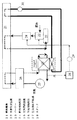
図1は、本発明の実施の形態における固体高分子型燃料電池システムを示す構成図である。水素を含む燃料ガスと空気を用いて発電を行う燃料電池21には、水素生成装置22から天然ガスなどの原料が水蒸気改質された水素リッチなガスが供給される。水素生成装置22には、改質反応に必要な温度まで昇温させるバーナー23が設置されている。水素生成装置22の出口には、燃料電池1に供給する燃料ガスを加湿する燃料側加湿器24が設置されている。また、酸化剤としての空気は、空気供給装置25から供給され、空気側加湿器26により加湿される。燃料側加湿器24および空気側加湿器26は、燃料電池21の高分子膜の特性を保つためのものである。
【0012】
空気側加湿器26は、燃料電池21から排出される空気から水蒸気を回収する湿度交換型熱交換器で構成されている。燃料電池21から排出され空気側加湿器26で湿度を下げた空気は、空気側水回収器27で外気により冷却され、さらに除湿される。得られた凝縮水は水タンク28に蓄えられる。回収された水は、燃料側水ポンプ29により水素生成装置22および燃料側加湿器24に送られ、燃料改質および燃料側加湿に利用される。燃料電池21では電気とともに熱が生じるために、冷却水を送る冷却用ポンプ30と、発生した熱を外部へ放出する冷却用放熱器31を備えている。
【0013】
次に、このような本実施の形態の動作を説明する。
【0014】
燃料電池21内部では、水素を含む改質ガスと空気が反応して大量の水蒸気が生じる。この水蒸気は、空気側流路で形成されるために、その大部分が空気側の出口から流出してくる。この時、液化した水が含まれる。本発明では、燃料電池21は最上部に位置するため、液化した水も滞留することなくスムーズに流下することができる。流出した空気は空気側加湿器26に流入する。空気側加湿器26では、空気供給装置25から供給される低温、低湿度の空気に水蒸気と熱を与える。このときの降温により凝縮水が生じる。凝縮水を含む空気は、下方に位置する空気側水回収器27に重力によりスムーズに流出する。空気側水回収器27は、外部空気により冷却され、水蒸気を凝縮させる。
【0015】
以上のように、本実施の形態の効果として、凝縮して生じる水滴を重力を利用してスムーズに流下することができることから、空気流路の圧力変動が抑えられる。これにより、空気の流れが安定し、電池内部の反応が一定状態で進み、高い効率が得られる。
【0016】
次に、本発明に関連する発明の実施の形態を図面を参照して説明する。
【0017】
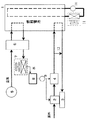
図2は、本発明に関連する発明の実施の形態における固体高分子型燃料電池システムを示す構成図である。水素を含む燃料ガスと空気を用いて発電を行う燃料電池41には、水素生成装置42から、天然ガスなどの原料が水蒸気改質された水素リッチなガスが供給される。水素生成装置42には、改質反応に必要な温度まで昇温させるバーナー43が設置されている。水素生成装置42の出口には、燃料電池41に供給する燃料ガスを加湿する燃料側加湿器44が設置されている。また、酸化剤としての空気は、空気供給装置45から供給され、空気側加湿器46により加湿される。燃料側加湿器44および空気側加湿器46は、燃料電池41の高分子膜の特性を保つためのものである。空気側加湿器46は、燃料電池41から排出される空気から水蒸気を回収する湿度交換型熱交換器で構成されている。燃料電池41から排出され空気側加湿器46で湿度を下げた空気は、空気側水回収器47で外気により冷却され、さらに除湿される。また、燃料電池41から排出された燃料ガスは、燃料側水回収器48で外気により冷却され、凝縮水を生じる。双方から得られた凝縮水は水タンク49に蓄えられる。回収された水は、燃料側水ポンプ50により水素生成装置42および燃料側加湿器44に送られ、燃料改質および燃料側加湿に利用される。燃料電池41では電気とともに熱が生じるために、冷却水を送る冷却用ポンプ51と、発生した熱を外部へ放出する冷却用放熱器52を備えている。
【0018】
水素生成装置42内では、天然ガスから水素リッチなガスを生成する改質反応を促進するために、温度が700℃程度になるようにバーナー43で加熱する。この改質反応には水蒸気が必要となるため、燃料側水ポンプ50より水が供給されている。水素生成装置42を出た燃料ガスは、燃料側加湿器44で加湿され、燃料電池41に送り込まれる。燃料電池41より排出される発電に用いられなかった燃料ガスは、バーナー43に送られ燃焼に利用される。このとき、燃料ガスは加湿時の水蒸気や、水素の消耗によって生じる水分を含んでいるが、燃料側水回収器48を経由することにより、水蒸気量を減らしてバーナー43に入る。
【0019】
次に、このような本発明に関連する発明の実施の形態に関する動作を説明する。
【0020】
起動時は改質に必要な温度に達しないために、充分に水素に変換することができない。このとき一酸化炭素を多く含むため、そのまま燃料電池41にガスを流すと燃料電池41の触媒が被毒し、特性を大きく低下させる。したがって、改質ガスを直接燃料側水回収器48に運ぶように、切り替え弁53を切り替える。これにより、一酸化炭素による被毒が回避できる。また、切り替えられた改質ガスは、燃料側水回収器48により、大量に含んだ水分を分離するため、バーナー43でスムーズに燃焼させることができる。したがって、改質ガスのエネルギーを有効利用でき、効率よく短時間で起動させることができる。
従来例の固体高分子型燃料電池システムでは、起動時に改質ガスをバイパスすると、改質ガスに含まれている水分によって、充分に燃焼することができず、臭気を発生したり、昇温時間が逆に長くなる場合があった。
対して本発明に関連する発明の固体高分子型燃料電池システムによれば、起動時の改質ガスの水蒸気を除湿した後に燃焼させることから、改質ガスのエネルギーを有効利用でき、効率よく短時間でスムーズに起動させることができる。
【0021】
【発明の効果】
以上説明したところから明らかなように、本発明は、高効率運転を図ることができる固体高分子型燃料電池システムを提供することができる。
【0022】
すなわち、空気流路内に生じる凝縮水を重力を利用してスムーズに排出させることにより、空気流路の圧力変動が抑えられ、電池内部の反応が一定状態で進み、高い効率が得られる。
【0024】
このように本発明によれば、高効率な運転が可能となるものである。
【図面の簡単な説明】
【図1】 本発明の実施の形態における固体高分子型燃料電池システムを示す構成図である。
【図2】 本発明に関連する発明の実施の形態における固体高分子型燃料電池システムを示す構成図である。
【図3】従来の固体高分子型燃料電池システムを示す構成図である。
【符号の説明】
1、21,41 燃料電池
2、22,42 水素生成装置
3、23,43 バーナー
4、24,44 燃料側加湿器
5、25,45 空気供給装置
6,26,46 空気側加湿器
7、27,47 空気側水回収器
8,28,49 水タンク
48 燃料側水回収器[0001]
BACKGROUND OF THE INVENTION
The present invention relates to a polymer electrolyte fuel cell system that generates electric power using a polymer electrolyte fuel cell.
[0002]
[Prior art]
Hereinafter, a conventional polymer electrolyte fuel cell system will be described.
[0003]
FIG. 3 shows a conventional polymer electrolyte fuel cell system. The
[0004]
In the
[0005]
[Problems to be solved by the invention]
However, when power generation is performed in the fuel cell system as in the above-described conventional example, a large amount of water vapor is generated in the
[0007]
The present invention, in consideration of the problems with such a conventional solid polymer electrolyte fuel cell system described above, to provide a highly efficient and stable polymer electrolyte fuel cell system capable you to ensure operation was It is intended.
[0008]
[Means for Solving the Problems]
The present invention (corresponding to the present invention described in claim 1) is at least
A polymer electrolyte fuel cell that generates electricity using hydrogen-containing fuel gas and air;
A humidity exchange type heat exchanger that performs heat exchange between the supply air to the fuel cell and the exhaust air from the fuel cell, and humidifies the supply air and dehumidifies the exhaust air;
An air-side water recovery device that condenses and recovers water vapor contained in the air discharged from the humidity exchange heat exchanger,
The fuel cell, the humidity exchanger heat exchanger, and the air-side water collector, the fuel cell is positioned at the top, the moisture exchanger heat exchanger below the fuel cell is located, the humidity The solid polymer fuel cell system is characterized in that the air side water recovery unit is located below the exchange type heat exchanger .
[0009]
Inventions related to the present invention includes at least a polymer electrolyte fuel cell that generates electricity by using a fuel gas and air, and the hydrogen generator to feed the steam reforming to produce a hydrogen-rich reformed gas A fuel-side water recovery device that condenses and recovers water vapor contained in the fuel gas discharged from the fuel cell, a bypass pipe that connects the outlet of the hydrogen generator and the inlet of the fuel-side water recovery device, and at startup The polymer electrolyte fuel cell system includes a switching mechanism that guides the reformed gas to the bypass pipe and guides the reformed gas to the fuel cell during normal operation.
[0010]
DETAILED DESCRIPTION OF THE INVENTION
Embodiments of the present invention will be described below with reference to the drawings.
[0011]
(In the form of implementation)
Figure 1 is a block diagram showing a polymer electrolyte fuel cell system in the implementation of the embodiment of the present invention. A hydrogen-rich gas obtained by steam reforming a raw material such as natural gas is supplied from a
[0012]
The air-
[0013]
Next, the operation of this embodiment will be described.
[0014]
Inside the
[0015]
As described above, as an effect of the present embodiment, water droplets generated by condensation can flow smoothly using gravity, so that pressure fluctuations in the air flow path can be suppressed. Thereby, the flow of air is stabilized, the reaction inside the battery proceeds in a constant state, and high efficiency is obtained.
[0016]
Next, embodiments of the invention related to the present invention will be described with reference to the drawings.
[0017]
FIG. 2 is a block diagram showing a polymer electrolyte fuel cell system according to an embodiment of the invention related to the present invention. A hydrogen-rich gas obtained by steam reforming a raw material such as natural gas is supplied from a
[0018]
In the
[0019]
Next, the operation relating to the embodiment of the invention related to the present invention will be described.
[0020]
Since it does not reach the temperature required for reforming at the time of start-up, it cannot be sufficiently converted to hydrogen. At this time, since a large amount of carbon monoxide is contained, if the gas is allowed to flow through the
In the polymer electrolyte fuel cell system of the conventional example, if the reformed gas is bypassed at the time of startup, the reformed gas cannot be burned sufficiently due to moisture contained in the reformed gas, and an odor is generated or the temperature rising time is increased. On the contrary, there was a case where it became longer.
On the other hand, according to the polymer electrolyte fuel cell system of the invention related to the present invention, since the steam of the reformed gas at the start-up is dehumidified and burned, the energy of the reformed gas can be used effectively and efficiently shortened. It can be started smoothly in time.
[0021]
【The invention's effect】
As apparent from the above description, the present invention can provide a polymer electrolyte fuel cell system which can achieve high efficiency OPERATION.
[0022]
That is, by smoothly discharging the condensed water generated in the air channel using gravity, the pressure fluctuation in the air channel is suppressed, the reaction inside the battery proceeds in a constant state, and high efficiency is obtained.
[0024]
Thus, according to the present invention, highly efficient operation is possible.
[Brief description of the drawings]
1 is a block diagram showing a polymer electrolyte fuel cell system in the implementation of the embodiment of the present invention.
FIG. 2 is a block diagram showing a polymer electrolyte fuel cell system in an embodiment of the invention related to the present invention.
FIG. 3 is a block diagram showing a conventional polymer electrolyte fuel cell system.
[Explanation of symbols]
1, 2, 41
Claims (1)
水素を含む燃料ガスと空気を用いて発電を行う固体高分子型の燃料電池と、
前記燃料電池への供給空気と前記燃料電池からの排出空気との間の熱交換を行うとともに、前記供給空気の加湿および前記排出空気の除湿を行う湿度交換型熱交換器と、
前記湿度交換型熱交換器より排出される空気に含まれる水蒸気を凝縮して回収する空気側水回収器とを備え、
前記燃料電池、前記湿度交換型熱交換器、及び前記空気側水回収器は、最上部に前記燃料電池が位置し、前記燃料電池の下方に前記湿度交換型熱交換器が位置し、前記湿度交換型熱交換器の下方に前記空気側水回収器が位置することを特徴とする固体高分子型燃料電池システム。at least,
A polymer electrolyte fuel cell that generates electricity using hydrogen-containing fuel gas and air;
A humidity exchange type heat exchanger that performs heat exchange between the supply air to the fuel cell and the exhaust air from the fuel cell, and humidifies the supply air and dehumidifies the exhaust air;
An air-side water recovery device that condenses and recovers water vapor contained in the air discharged from the humidity exchange heat exchanger,
The fuel cell, the humidity exchanger heat exchanger, and the air-side water collector, the fuel cell is positioned at the top, the moisture exchanger heat exchanger below the fuel cell is located, the humidity The polymer electrolyte fuel cell system , wherein the air-side water recovery unit is located below the exchange heat exchanger .
Priority Applications (1)
| Application Number | Priority Date | Filing Date | Title |
|---|---|---|---|
| JP32714398A JP3685936B2 (en) | 1998-11-17 | 1998-11-17 | Polymer electrolyte fuel cell system |
Applications Claiming Priority (1)
| Application Number | Priority Date | Filing Date | Title |
|---|---|---|---|
| JP32714398A JP3685936B2 (en) | 1998-11-17 | 1998-11-17 | Polymer electrolyte fuel cell system |
Related Child Applications (1)
| Application Number | Title | Priority Date | Filing Date |
|---|---|---|---|
| JP2005121706A Division JP2005251759A (en) | 2005-04-19 | 2005-04-19 | Polymer electrolyte fuel cell system |
Publications (3)
| Publication Number | Publication Date |
|---|---|
| JP2000156236A JP2000156236A (en) | 2000-06-06 |
| JP3685936B2 true JP3685936B2 (en) | 2005-08-24 |
| JP2000156236A5 JP2000156236A5 (en) | 2005-09-22 |
Family
ID=18195803
Family Applications (1)
| Application Number | Title | Priority Date | Filing Date |
|---|---|---|---|
| JP32714398A Expired - Lifetime JP3685936B2 (en) | 1998-11-17 | 1998-11-17 | Polymer electrolyte fuel cell system |
Country Status (1)
| Country | Link |
|---|---|
| JP (1) | JP3685936B2 (en) |
Cited By (1)
| Publication number | Priority date | Publication date | Assignee | Title |
|---|---|---|---|---|
| EP2178149A3 (en) * | 2001-05-23 | 2010-11-24 | Panasonic Corporation | Fuel cell power generation system |
Families Citing this family (17)
| Publication number | Priority date | Publication date | Assignee | Title |
|---|---|---|---|---|
| US6436563B1 (en) * | 2000-06-13 | 2002-08-20 | Hydrogenics Corporation | Water recovery, primarily in the cathode side, of a proton exchange membrane fuel cell |
| JP2002280032A (en) | 2001-03-21 | 2002-09-27 | Nissan Motor Co Ltd | Fuel cell system |
| JP2002352844A (en) * | 2001-05-24 | 2002-12-06 | Matsushita Electric Ind Co Ltd | Fuel cell system |
| US6824906B2 (en) * | 2001-07-16 | 2004-11-30 | Modine Manufacturing Company | Fuel cell system incorporating and integrated cathode exhaust condenser and stack cooler |
| KR20030018921A (en) * | 2001-08-31 | 2003-03-06 | 현대자동차주식회사 | Fuel cell system for vehicles |
| FR2833761B1 (en) * | 2001-12-14 | 2004-07-16 | Peugeot Citroen Automobiles Sa | DEVICE FOR GENERATING ELECTRICITY OF THE FUEL CELL TYPE AND VEHICLE COMPRISING SUCH A DEVICE |
| JP4790964B2 (en) * | 2002-12-24 | 2011-10-12 | 本田技研工業株式会社 | Fuel cell with dehumidifying device |
| CN1571204A (en) * | 2003-07-14 | 2005-01-26 | 亚太燃料电池科技股份有限公司 | Cooling device of air cooling type fuel battery |
| JP4959112B2 (en) * | 2004-02-19 | 2012-06-20 | アイシン精機株式会社 | Fuel cell system |
| JP4886970B2 (en) * | 2004-03-25 | 2012-02-29 | アイシン精機株式会社 | Fuel cell system |
| JP4940822B2 (en) * | 2006-08-11 | 2012-05-30 | 株式会社エクォス・リサーチ | Fuel cell system |
| JP2008047327A (en) * | 2006-08-11 | 2008-02-28 | Equos Research Co Ltd | Fuel cell system |
| JP5052297B2 (en) * | 2007-11-09 | 2012-10-17 | トヨタ自動車株式会社 | Fuel cell |
| US20100248045A1 (en) * | 2007-11-22 | 2010-09-30 | Osamu Sakai | Fuel cell system and method for operating the same |
| JP5495637B2 (en) * | 2009-06-30 | 2014-05-21 | Jx日鉱日石エネルギー株式会社 | Fuel cell system |
| US9774046B2 (en) * | 2015-07-17 | 2017-09-26 | Ford Global Technologies, Llc | Humidification system and method for a fuel cell |
| CN108155401B (en) * | 2018-01-23 | 2023-08-04 | 同济大学 | High-flow low-temperature gas temperature and humidity control equipment |
-
1998
- 1998-11-17 JP JP32714398A patent/JP3685936B2/en not_active Expired - Lifetime
Cited By (1)
| Publication number | Priority date | Publication date | Assignee | Title |
|---|---|---|---|---|
| EP2178149A3 (en) * | 2001-05-23 | 2010-11-24 | Panasonic Corporation | Fuel cell power generation system |
Also Published As
| Publication number | Publication date |
|---|---|
| JP2000156236A (en) | 2000-06-06 |
Similar Documents
| Publication | Publication Date | Title |
|---|---|---|
| JP3685936B2 (en) | Polymer electrolyte fuel cell system | |
| JP5616064B2 (en) | Fuel cell heat exchange system and method | |
| JP4738480B2 (en) | Fuel cell system | |
| US6312842B1 (en) | Water retention system for a fuel cell power plant | |
| US20020015870A1 (en) | Fuel cell electric power generation system | |
| KR100482709B1 (en) | Solid polymer fuel cell | |
| JP2000156236A5 (en) | ||
| JP3809646B2 (en) | Fuel cell device | |
| JP2000164233A (en) | Power generating system for solid high molecular fuel cell | |
| JP2001015139A (en) | Fuel cell system | |
| JP4419329B2 (en) | Solid polymer electrolyte fuel cell power generator | |
| JP3943405B2 (en) | Fuel cell power generation system | |
| KR20030073679A (en) | Cooling water recycling system for fuel cell | |
| JP2001185197A (en) | Fuel cell system | |
| JP2006318798A (en) | Fuel cell system | |
| JP2005251759A (en) | Polymer electrolyte fuel cell system | |
| JP4528570B2 (en) | Fuel cell cogeneration system | |
| JPH10321246A (en) | Fuel cell system | |
| JP3377523B2 (en) | Fuel cell system | |
| JP4176130B2 (en) | Fuel cell power generation system | |
| JP4610906B2 (en) | Fuel cell power generation system and method for starting fuel cell power generation system | |
| JP4000971B2 (en) | Fuel cell system | |
| JP2005347120A (en) | Fuel cell power generation system | |
| JP3831836B2 (en) | Solid polymer fuel cell power generator | |
| JPH06111841A (en) | Solid high polymer electrolyte type fuel cell system |
Legal Events
| Date | Code | Title | Description |
|---|---|---|---|
| A521 | Written amendment |
Free format text: JAPANESE INTERMEDIATE CODE: A523 Effective date: 20050412 |
|
| TRDD | Decision of grant or rejection written | ||
| A01 | Written decision to grant a patent or to grant a registration (utility model) |
Free format text: JAPANESE INTERMEDIATE CODE: A01 Effective date: 20050524 |
|
| A61 | First payment of annual fees (during grant procedure) |
Free format text: JAPANESE INTERMEDIATE CODE: A61 Effective date: 20050601 |
|
| R150 | Certificate of patent or registration of utility model |
Free format text: JAPANESE INTERMEDIATE CODE: R150 |
|
| FPAY | Renewal fee payment (event date is renewal date of database) |
Free format text: PAYMENT UNTIL: 20080610 Year of fee payment: 3 |
|
| FPAY | Renewal fee payment (event date is renewal date of database) |
Free format text: PAYMENT UNTIL: 20090610 Year of fee payment: 4 |
|
| FPAY | Renewal fee payment (event date is renewal date of database) |
Free format text: PAYMENT UNTIL: 20100610 Year of fee payment: 5 |
|
| FPAY | Renewal fee payment (event date is renewal date of database) |
Free format text: PAYMENT UNTIL: 20100610 Year of fee payment: 5 |
|
| FPAY | Renewal fee payment (event date is renewal date of database) |
Free format text: PAYMENT UNTIL: 20110610 Year of fee payment: 6 |
|
| FPAY | Renewal fee payment (event date is renewal date of database) |
Free format text: PAYMENT UNTIL: 20120610 Year of fee payment: 7 |
|
| FPAY | Renewal fee payment (event date is renewal date of database) |
Free format text: PAYMENT UNTIL: 20120610 Year of fee payment: 7 |
|
| FPAY | Renewal fee payment (event date is renewal date of database) |
Free format text: PAYMENT UNTIL: 20130610 Year of fee payment: 8 |
|
| EXPY | Cancellation because of completion of term |