JP3685794B2 - Projection display - Google Patents
Projection display Download PDFInfo
- Publication number
- JP3685794B2 JP3685794B2 JP2003315509A JP2003315509A JP3685794B2 JP 3685794 B2 JP3685794 B2 JP 3685794B2 JP 2003315509 A JP2003315509 A JP 2003315509A JP 2003315509 A JP2003315509 A JP 2003315509A JP 3685794 B2 JP3685794 B2 JP 3685794B2
- Authority
- JP
- Japan
- Prior art keywords
- light
- diaphragm
- light shielding
- opening
- projection
- Prior art date
- Legal status (The legal status is an assumption and is not a legal conclusion. Google has not performed a legal analysis and makes no representation as to the accuracy of the status listed.)
- Expired - Lifetime
Links
Images


Description
本発明は、主としてライトバルブ上に形成された光学像をスクリーン上に拡大投写する投写型表示装置に関する。 The present invention relates to a projection display apparatus that mainly enlarges and projects an optical image formed on a light valve on a screen.
大画面映像を得るために、ライトバルブに映像信号に応じた光学像を形成し、その光学像に光を照射し、投写レンズによりスクリーン上に拡大投写する方法が従来よりよく知られている。ライトバルブとして、反射型ライトバルブを用いれば、高い解像度と高い画素開口率を両立させることができ、光利用効率の高い高輝度の投写画像を表示できる。 In order to obtain a large screen image, a method of forming an optical image corresponding to a video signal on a light valve, irradiating the optical image with light, and enlarging and projecting onto a screen by a projection lens is well known. If a reflective light valve is used as the light valve, both high resolution and high pixel aperture ratio can be achieved, and a high-luminance projection image with high light utilization efficiency can be displayed.
反射型ライトバルブを用いた従来例に係る投写型表示装置の光学系の構成図を図10に示す。光源としてのランプ1から放射される光を反射型ライトバルブ6上に集光及び照明する照明光学系は、凹面鏡2、断面が反射型ライトバルブ6の有効表示面と略同じアスペクト比の四角柱状のロッドプリズム3、コンデンサレンズ4、及び集光ミラー5によって構成される。
FIG. 10 shows a configuration diagram of an optical system of a projection display apparatus according to a conventional example using a reflective light valve. The illumination optical system for condensing and illuminating the light emitted from the
凹面鏡2は反射面の断面形状が楕円形をなし、第1焦点と第2焦点を有する。ランプ1の発光体の中心が凹面鏡2の第1焦点付近に位置するように配置され、ロッドプリズム3の光入射面が凹面鏡2の第2焦点付近に位置するように配置されている。また、凹面鏡2はガラス製基材の内面に赤外光を透過させ可視光を反射させる光学多層膜を形成させたものである。
The
ランプ1から放射される光は凹面鏡2により反射及び集光され、凹面鏡2の第2焦点にランプ1の発光体像を形成する。ランプ1の発光体像は光軸に近い中心付近が最も明るく、周辺ほど急激に暗くなる傾向にあるため、輝度に不均一性が残る。この問題に対し、第2焦点付近にロッドプリズム3の入射面を配置し、ロッドプリズム3の側面で入射光を多重反射させて輝度の均一化を図り、ロッドプリズム3の出射面を2次面光源として以降のコンデンサレンズ4、集光ミラー5によって、反射型ライトバルブ6上に結像させれば、照明光の均一性を確保することができる。
The light emitted from the
ここで、反射型ライトバルブ6の動作について、図11を用いて説明する。反射型ライトバルブ6は映像信号に応じて光の進行方向を制御し反射角の変化として光学像が形成されるものである。画素ごとにミラー素子21がマトリックス状に形成され、各ミラー素子21は白表示としてのON信号と黒表示としてのOFF信号でそれぞれ±θ゜だけ投写レンズの光軸と垂直な平面22に対して傾く。照明主光線24はカバーガラス23を透過後ミラー素子21に入射及び反射され、再びカバーガラス23を出射する。
Here, the operation of the
図11Aに示すように、まず、ON信号時において、照明主光線24の入射角は、ON光主光線25が平面22と垂直な方向、即ち投写レンズの光軸に沿って反射及び進行するように設定する。この場合、照明主光線24とON光主光線25とのなす角度は2θとなる。また、図11Bに示すように、OFF信号時においては、OFF光主光線26が投写レンズに入射しない方向に反射及び進行し、照明主光線24とOFF光主光線26とのなす角度は6θとなる。
As shown in FIG. 11A, first, at the time of an ON signal, the incident angle of the
図10に示すように、反射型ライトバルブ6に入射する照明光8は、ON信号時にはON光9として投写レンズ7に入射し、OFF信号時にはOFF光10として投写レンズ7の有効径の外に進行する。このようにON光9とOFF光10の時間配分を映像信号に応じて制御することによりスクリーン上に投写画像を形成する。
As shown in FIG. 10, the illumination light 8 incident on the
しかしながら、図11に示したカバーガラス23と外部媒質の空気との界面で発生する反射光は、図10においては斜線部である不要反射光11として進行し、その一部は投写レンズ7に入射する。この不要反射光11は、ON/OFFいずれの信号時においても同様に進行するため、特にOFF進行時の黒表示の品位に著しく悪影響を及ぼし、コントラスト性能を劣化させる要因となるという問題があった。
However, the reflected light generated at the interface between the
本発明は、前記のような従来の問題を解決するものであり、必要光の遮光を抑えて、明るさの低下を最小限に抑えながら、コントラスト性能を向上させることができる投写型表示装置を提供することを目的とする。 The present invention solves the conventional problems as described above, and provides a projection display device capable of improving the contrast performance while suppressing the necessary light and minimizing the decrease in brightness. The purpose is to provide.
前記目的を達成するために、本発明の投写型表示装置は、光源と、画素毎に形成されたミラー素子を有する反射型ライトバルブと、前記光源からの放射光を前記反射型ライトバルブ上に集光する照明光学系と、前記放射光が前記反射型ライトバルブの前記ミラー素子によって反射された光をスクリーン上に拡大投写する投写レンズと、前記投写レンズ中又は前記照明光学系中のいずれかの位置に配置され、前記投写レンズからスクリーン上に投写される光の光線束の断面積の大きさを決定する絞りとを備え、前記絞りは、開口を有する固定絞りと、前記開口における光線束の一部を遮光可能な遮光板とで構成されており、前記遮光板を前記照明光学系の光軸又は前記投写レンズの光軸に向かう方向へ変位可能に構成し、前記遮光板の変位により前記反射型ライトバルブの前面で反射された不要反射光のスクリーン上への投写を低減可能にしたことを特徴とする。 In order to achieve the above object, a projection display device according to the present invention includes a light source, a reflective light valve having a mirror element formed for each pixel , and radiated light from the light source on the reflective light valve. An illumination optical system that condenses, a projection lens that enlarges and projects the light reflected by the mirror element of the reflective light valve onto the screen, and either the projection lens or the illumination optical system And a diaphragm that determines the size of the cross-sectional area of the light beam projected from the projection lens onto the screen, the diaphragm having a fixed diaphragm having an aperture, and the beam bundle at the aperture A part of the light shielding plate, and the light shielding plate is configured to be displaceable in a direction toward the optical axis of the illumination optical system or the optical axis of the projection lens. Yo Characterized in that to allow reducing the projection to the reflection type light of the unwanted light reflected by the front surface of the valve on the screen.
本発明によれば、遮光手段によって遮光された遮光部の形状を照明光学系の光軸に対して非回転対称とすることにより、必要光の遮光を抑えることができるので、明るさの低下を最小限に抑えながら、コントラスト性能を向上させることができる。 According to the present invention, since the shape of the light-shielding part shielded by the light-shielding means is non-rotationally symmetric with respect to the optical axis of the illumination optical system, the necessary light can be prevented from being shielded. Contrast performance can be improved while minimizing.
本発明に係る投写型表示装置によれば、必要光の遮光を抑えることができるので、明るさの低下を最小限に抑えながら、コントラスト性能を向上させることができる。 According to the projection display device of the present invention, since it is possible to suppress the necessary light from being blocked, it is possible to improve the contrast performance while minimizing the decrease in brightness.
前記投写型表示装置においては、前記開口のうち前記遮光板で遮光された部分を除く前記開口の形状は、前記照明光学系又は前記投写レンズの光軸に対して非回転対称であることが好ましい。
また、遮光手段と前記遮光手段の可動手段とをさらに備えており、前記絞りの開口の形状は、前記遮光手段により遮光された形状であり、前記遮光手段により遮光された形状は、前記照明光学系又は前記投写レンズの光軸に対して非回転対称であり、前記可動手段は前記遮光手段を変位させて、前記開口の面積を可変できることが好ましい。前記のような投写型表示装置によれば、回転対称に遮光する絞り、例えば開口を同心円状に狭めて行く絞りに比べ、必要光の遮光を抑えることができるので、明るさの低下を最小限に抑えながら、コントラスト性能を向上させることができる。また、コントラスト性能と光出力とを任意に調整できる。
In the projection display device, it is preferable that a shape of the opening excluding a portion shielded by the light shielding plate in the opening is non-rotationally symmetric with respect to an optical axis of the illumination optical system or the projection lens. .
The light shielding means and further comprising a movable means of the light shielding means, the shape of the aperture of the diaphragm has a shape which is shielded by the shielding means, a shape which is shielded by the shielding means, the illumination optical It is preferably non-rotationally symmetric with respect to the optical axis of the system or the projection lens, and the movable means can displace the light shielding means to change the area of the opening. According to the projection display apparatus as described above, since the necessary light can be prevented from being blocked as compared with a diaphragm that shields light in a rotationally symmetrical manner, for example, a diaphragm that concentrically narrows the aperture, the reduction in brightness is minimized. Contrast performance can be improved while suppressing to a low level. Further, the contrast performance and the light output can be arbitrarily adjusted.
また、前記照明光学系からの照明光を前記反射型ライトバルブへ反射し、前記反射型ライトバルブからの反射光を透過するプリズムをさらに備えたことが好ましい。前記のような投写型表示装置によれば、照明光学系をコンパクトに構成でき、プリズム界面で発生する不要反射光についても、明るさの低下を最小限に抑えながら、カットすることができる。 It is preferable that the apparatus further includes a prism that reflects illumination light from the illumination optical system to the reflective light valve and transmits reflected light from the reflective light valve. According to the projection display apparatus as described above, the illumination optical system can be made compact, and unnecessary reflected light generated at the prism interface can be cut while minimizing the decrease in brightness.
また、前記反射型ライトバルブを3つ有しており、前記照明光学系からの照明光を前記反射型ライトバルブへ反射し、前記反射型ライトバルブからの反射光を透過する第1のプリズムと、前記照明光を赤、青、及び緑の3原色光に分解し、かつ前記3原色光に対応した前記各反射型ライトバルブからの反射光を1つに合成する第2のプリズムとをさらに備えたことが好ましい。前記のような投写型表示装置によれば、高精細でフルカラーの投写画像を表示でき、第1のプリズム、及び第2のプリズムの界面で発生する不要反射光についても、明るさの低下を最小限に抑えながら、カットすることができる。 A first prism configured to reflect the illumination light from the illumination optical system to the reflection light valve and transmit the reflection light from the reflection light valve; A second prism that separates the illumination light into three primary color lights of red, blue, and green, and combines the reflected light from each of the reflection type light valves corresponding to the three primary color lights. It is preferable to provide. According to the projection display device as described above, it is possible to display a high-definition, full-color projection image, and it is possible to minimize a decrease in brightness of unnecessary reflected light generated at the interface between the first prism and the second prism. It is possible to cut while limiting to the limit.
また、前記反射型ライトバルブは、画像形成面と、前記画像形成面の出射側に、前記画像形成面と平行に配置された透明板とを有していることが好ましい。 The reflection type light valve preferably includes an image forming surface and a transparent plate arranged in parallel with the image forming surface on the emission side of the image forming surface.
また、前記反射型ライトバルブは、映像信号に応じて光の反射方向を制御する複数のミラー素子がマトリックス状に配列されていることが好ましい。 In the reflection type light valve, it is preferable that a plurality of mirror elements that control the reflection direction of light according to a video signal are arranged in a matrix.
また、前記照明光学系からの照明光は、前記反射型ライトバルブに斜め方向から入射し、
前記照明光の外周と前記反射型ライトバルブからの不要反射光の外周とが最も近接する前記遮光手段の位置を基準位置とすると、
前記遮光手段は、前記可動手段により、前記基準位置から前記光軸に向かう一方向に移動でき、前記一方向の移動を継続するにつれて、前記絞りの遮光面積が増大することが好ましい。前記のような投写型表示装置によれば、前記反射型ライトバルブからの不要反射光を光軸側から順にカットすることができる。
The illumination light from the illumination optical system is incident on the reflective light valve from an oblique direction,
When the position of the light shielding means where the outer periphery of the illumination light and the outer periphery of unnecessary reflected light from the reflective light valve are closest is a reference position,
The light shielding means can be moved in one direction from the reference position toward the optical axis by the movable means, and it is preferable that the light shielding area of the diaphragm increases as the movement in the one direction is continued. According to the projection display device as described above, unnecessary reflected light from the reflective light valve can be cut in order from the optical axis side.
また、前記絞りの開口の形状は、開放状態では円形であることが好ましい。 In addition, the shape of the aperture of the diaphragm is preferably circular in the open state.
また、前記遮光手段により遮光された遮光部の形状が、略半円形状であることが好ましい。前記のような投写型表示装置によれば、光軸に対して非回転対称である遮光部の形状を容易に形成できる。 Moreover, it is preferable that the shape of the light-shielding part shielded by the light-shielding means is a substantially semicircular shape. According to the projection display device as described above, the shape of the light shielding portion that is non-rotationally symmetric with respect to the optical axis can be easily formed.
また、前記遮光手段の一辺は、前記絞りを平面方向について見ると、前記光軸上の点を通る水平線と平行な直線であり、前記平行な直線と、前記絞りの開口の内周線とで囲まれる遮光部の形状が略半円形状であることが好ましい。 Further, when the diaphragm is viewed in the planar direction, one side of the light shielding means is a straight line parallel to a horizontal line passing through a point on the optical axis, and the parallel straight line and an inner peripheral line of the aperture of the diaphragm It is preferable that the shape of the light-shielding part enclosed is a substantially semicircle shape.
また、前記遮光手段により遮光された遮光部の形状が、略三日月形状であることが好ましい。前記のような投写型表示装置によれば、光軸に対して非回転対称である遮光部の形状を容易に形成できる。 Moreover, it is preferable that the shape of the light-shielding part light-shielded by the said light-shielding means is a substantially crescent moon shape. According to the projection display device as described above, the shape of the light shielding portion that is non-rotationally symmetric with respect to the optical axis can be easily formed.
また、前記遮光手段は、円形の開口を有しており、前記円形の開口を前記絞りの開口に対して偏心させることにより前記遮光部が形成され、前記遮光手段の開口の内周線と、前記絞りの開口の内周線とで囲まれる前記遮光部の形状が略三日月形状であることが好ましい。 Further, the light shielding means has a circular opening, the light shielding portion is formed by decentering the circular opening with respect to the aperture of the diaphragm, and an inner peripheral line of the opening of the light shielding means, It is preferable that the shape of the light shielding portion surrounded by the inner peripheral line of the aperture of the diaphragm is a substantially crescent shape.
また、前記遮光手段は、内径寸法が変化可能で、前記絞りの開口に対して偏心して配置された開口を有しており、前記遮光手段の開口の内周線と、前記絞りの開口の内周線とで囲まれる前記遮光部の形状が略三日月形状であり、前記遮光手段の開口の内径寸法を変化させることにより、前記遮光部の面積が変化することが好ましい。 The shading means may have an inner diameter that is variable, and has an opening that is eccentric with respect to the aperture of the diaphragm, and the inner circumference of the opening of the shading means and the aperture of the aperture It is preferable that the shape of the light-shielding portion surrounded by the peripheral line is a substantially crescent shape, and the area of the light-shielding portion is changed by changing the inner diameter dimension of the opening of the light-shielding means.
また、前記絞りを平面方向について見た場合、前記絞りの開口のうち光軸上の点を通る水平線に対して上側を上側部分、下側を下側部分とすると、前記絞りの開口は、前記上側部分又は下側部分のいずれか一方の側から他方の側へと順次、前記遮光手段により遮光されることにより、遮光面積が増大することが好ましい。 Further, when the diaphragm is viewed in a planar direction, when the upper side is an upper part and the lower side is a lower part with respect to a horizontal line passing through a point on the optical axis, the aperture of the diaphragm is It is preferable that the light shielding area is increased by the light shielding means sequentially shielding light from one side of the upper part or the lower part to the other side.
また、前記遮光手段の表面は、入射する光を80%以上の反射率で反射する金属、又は誘電体多層膜で形成されていることが好ましい。前記のような投写型表示装置によれば、光吸収量を抑えることができ、遮光部表面の温度が高温となり、輻射熱によって周辺の光学部品が破損することを防止できる。 The surface of the light shielding means is preferably formed of a metal or dielectric multilayer film that reflects incident light with a reflectance of 80% or more. According to the projection display apparatus as described above, the amount of light absorption can be suppressed, the temperature of the surface of the light shielding portion becomes high, and the surrounding optical components can be prevented from being damaged by radiant heat.
また、前記可動手段による前記遮光手段の変位量を制御する制御手段を備えており、前記絞りの遮光量が、入力される映像信号のレベルに応じて変化するように前記制御手段により制御されることが好ましい。前記のような投写型表示装置によれば、例えば、暗いシーンほどコントラストや黒レベルの低さを重視し、明るいシーンほど白レベルの高さを重視するように制御すれば、よりコントラスト感の高い表示性能を得ることができる。 In addition, a control unit that controls a displacement amount of the light shielding unit by the movable unit is provided, and the light shielding amount of the diaphragm is controlled by the control unit so as to change according to a level of an input video signal. It is preferable. According to the projection display device as described above, for example, if the dark scene is controlled so that the contrast and the black level are emphasized, and the bright scene is controlled so that the white level is emphasized, the contrast is higher. Display performance can be obtained.
また、前記絞りの遮光量を装置の外部から制御できることが好ましい。前記のような投写型表示装置によれば、使用用途に応じて、明るさ重視の投写画像とコントラスト重視の投写画像とを任意に選択できる。 Further, it is preferable that the light shielding amount of the diaphragm can be controlled from the outside of the apparatus. According to the projection display device as described above, it is possible to arbitrarily select a brightness-oriented projection image and a contrast-oriented projection image according to the intended use.
以下、本発明の一実施形態について、図面を参照しながら、参照しながら説明する。 Hereinafter, an embodiment of the present invention will be described with reference to the drawings.
(実施の形態1)
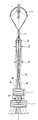
図1は、本発明の実施形態1に係る投写型表示装置の概略構成を示している。同図において、1は光源としてのランプ、31は絞り、6は反射型ライトバルブ、7は投写レンズである。また、凹面鏡2、ロッドプリズム3、コンデンサレンズ4、集光ミラー5によって構成される光学系を総称して照明光学系と呼ぶ。12は照明光学系の光軸を示している。
(Embodiment 1)
FIG. 1 shows a schematic configuration of a projection display apparatus according to
画像形成手段である反射型ライトバルブ6は、図10を用いて説明した通り、画素毎にミラー素子21がマトリックス状に形成され、映像信号に応じて光の進行方向を制御し反射角の変化として光学像が形成されるものである。凹面鏡2は、反射面の断面形状が楕円形をなす楕円面鏡であり、第1焦点と第2焦点を有する。
As described with reference to FIG. 10, the reflective
ランプ1としてキセノンランプを用いており、発光体の中心が凹面鏡2の第1焦点付近に位置するように配置され、ロッドプリズム3の光入射面が凹面鏡2の第2焦点付近に位置するように配置されている。また、凹面鏡2は、ガラス製基材の内面に赤外光を透過させて可視光を反射させる光学多層膜を形成したものである。
A xenon lamp is used as the
ロッドプリズム3は、光の入射面及び出射面が反射型ライトバルブ6の有効表示面と同じアスペクト比である四角柱であり、ランプ1からの放射光が集光される場所に配置されるため、材質は耐熱性に優れる石英ガラスからなる。ロッドプリズム3の入射面付近に凹面鏡2によって集光されたランプ1の発光体像を形成させる。凹面鏡2によって集光されたランプ1の発光体像は光軸12に近い中心付近が最も明るく、周辺ほど急激に暗くなる傾向にあるため、面内に輝度の不均一性が残る。
The rod prism 3 is a quadrangular prism whose light entrance surface and light exit surface have the same aspect ratio as the effective display surface of the reflective
これに対し、ロッドプリズム3に入射した光線束はロッドプリズム3の側面で多重反射され、反射回数分だけ発光体像が細分割及び重畳されて照明されるため、ロッドプリズム3の出射面においては輝度が均一化される。このようにランプ発光体像の細分割及び重畳効果によって、ロッドプリズム3内で反射される回数が多いほど均一性が向上する。このため、均一性の度合いはロッドプリズム3の長さに依存する。本実施形態においては、スクリーン上の周辺照度が中心照度に対して90%以上となるようにロッドプリズム3の長さを設定した。 On the other hand, since the light beam incident on the rod prism 3 is multiple-reflected on the side surface of the rod prism 3 and the illuminant image is subdivided and superimposed as many times as the number of reflections, it is illuminated on the exit surface of the rod prism 3. The brightness is made uniform. Thus, due to the subdivision and superimposing effect of the lamp illuminant image, the greater the number of reflections within the rod prism 3, the better the uniformity. For this reason, the degree of uniformity depends on the length of the rod prism 3. In the present embodiment, the length of the rod prism 3 is set so that the peripheral illuminance on the screen is 90% or more with respect to the central illuminance.
このように輝度が均一化されたロッドプリズム3の出射面を2次面光源とし、それ以降に配置されているコンデンサレンズ4と集光ミラー5によって、反射型ライトバルブ6の有効表示面積とマッチングする倍率で結像させれば、集光効率の確保と均一性の向上とを両立させることができる。ランプ1から放射される光は照明光学系によって集光され、照明光32は反射型ライトバルブ6に入射する。
The exit surface of the rod prism 3 with uniform luminance is used as a secondary surface light source, and the effective display area of the reflective
反射型ライトバルブ6に入射した照明光32うち、白表示に相当するON光33は投写レンズ7に入射してスクリーン上(図示せず)に拡大投写される。一方、黒表示に相当するOFF光34は投写レンズ7の有効径外に進行し、スクリーンには到達しない。
Of the
以下、図2を用いて各光学部材の位置関係を、より具体的に説明する。
図2に示した投写型表示装置は、各光学部材の位置関係の理解を容易にするため、図1に示した構成において、光軸が同一線上となるように展開したものである。
Hereinafter, the positional relationship of each optical member will be described more specifically with reference to FIG.
The projection display apparatus shown in FIG. 2 is developed so that the optical axes are on the same line in the configuration shown in FIG. 1 in order to facilitate understanding of the positional relationship between the optical members.
すなわち、図1に示した構成のうち、反射要素である集光ミラー5を、透過要素であるレンズ5aに置き換え、かつ反射要素である反射型ライトバルブ6を透過要素であるライトバルブ6aに置き換えてている。図2中、斜線で示している光線束は、軸上光線束90であり、91及び92は軸外光線束である。
That is, in the configuration shown in FIG. 1, the condensing
ランプ1の発光体像は、楕円面鏡2によってロッドプリズム3の入射面に結像される。ロッドプリズム3を通る光は,ロッドプリズム3の内面で多重反射を繰り返して、出射面側では輝度が均一化される。
The luminous body image of the
ロッドプリズム3の出射面を2次平面光源像とすると、この光源像はレンズ4a、5aによってライトバルブ6aに結像し、さらに投写レンズ7によってスクリーン上(図示せず)に結像する。すなわち、ロッドプリズム3の出射面とライトバルブ6aの光学像形成面との関係は、互いに共役な関係にあり、ライトバルブ6aの光学像形成面とスクリーン面との関係も互いに共役な関係にある。
When the exit surface of the rod prism 3 is a secondary planar light source image, this light source image is formed on the
一方、絞り31aは、図1の絞り31に対応する絞りであり、照明光学系の光路中に配置されており、レンズ4a、レンズ5aとの間にある。絞り93は、投写レンズ7中に配置されている。絞り31a、及び絞り93は、軸上光線束90、軸外光線束91、及び軸外光線束92の光線束断面積の大きさを決定する開口絞りである。絞り93は投写レンズ7の入射瞳の位置に配置されており、絞り31aは絞り93と略共役な位置に配置されている。
On the other hand, the
なお、各実施形態に係る図1及び図5以降の構成は、光軸が同一線上にはないが、共役な関係については、図2の構成と同様である。また、これらの各図では、不要光の作用を説明するため、軸外光線束の図示は省略している。 1 and FIG. 5 and subsequent configurations according to each embodiment are not the same in the optical axis, but the conjugate relationship is the same as the configuration in FIG. Further, in each of these drawings, the illustration of the off-axis ray bundle is omitted in order to explain the action of unnecessary light.
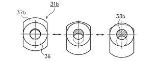
図3に、図1に示した絞り31の具体例を示している。各図において、固定絞り36は、光が透過する開口を有しており、配置位置及び開口形状が固定されている。絞りは、この固定絞り36と、遮光手段である遮光板37a、37b、又は37cとの組み合わせによって構成される。
FIG. 3 shows a specific example of the
本実施形態に係る遮光手段は、可動手段によって変位が可能であり、この変位によって、遮光面積を可変できる。遮光手段の変位とは、遮光手段の位置の移動や、遮光手段の開口面積変化のような遮光手段自体の形状変化も含んでいる。 The light shielding means according to the present embodiment can be displaced by the movable means, and the light shielding area can be varied by this displacement. The displacement of the light shielding means includes the movement of the position of the light shielding means and the shape change of the light shielding means itself such as the change in the opening area of the light shielding means.
図3Aに示した絞り31aは、固定絞り36と、遮光手段である遮光板37aとを備えている。本図において、固定絞り36の開口の一部は、遮光板37aによって、遮光されている。斜線部が遮光部(例えば、右端図の符号38aで示した部分。図3B、Cの符号38b、38cについても同じ。)である。
The
本図に示したように遮光板37aが下方に移動するにつれて、遮光面積が大きくなる。遮光板37aは、固定絞り36の開口の中心36a(図1の光軸12上の点)を通る水平線39と平行な直線である辺37dを有している。このため、辺37dと、固定絞りの開口の内周線とで囲まれる遮光部の形状が略半円形状となっている。このことは、遮光板37aを下方に移動させても同様であり、辺37dと水平線39とが一致すれば、遮光部は完全な半円形状となる。
As shown in this figure, the light shielding area increases as the
図3Bに示した絞り31bは、遮光手段である遮光板37bには、開口が形成されている。本図に示した例においても、図3Aに示した例と同様に、遮光板37bが下方に移動するにつれて、遮光面積が変化する。すなわち、遮光板37bの開口と、固定絞り36の開口との偏心量が大きくなるにつれて、遮光面積が大きくなる。本図に示した例では、遮光板37bの開口の内周線と、固定絞り36の開口の内周線とで囲まれる遮光部の形状が略三日月形状となっている。
In the
図3Cに示した絞り31cについては、遮光手段である遮光板37cには、開口が形成されている。遮光板37cの開口は、開口径が変化可能であり、遮光面積を可変できる。すなわち、本図に示したように、遮光板37cの開口径が小さくなるにつれて、遮光面積は大きくなる。また、本図の例も図3Bの例と同様に、遮光板37cの開口の内周線と、固定絞り36の開口の内周線とで囲まれる遮光部の形状が略三日月形状となっている。
In the
ここで、図3Aに示した絞り31aを例にとると、遮光板37aの辺37dが固定絞り36の開口の上方にある場合は、遮光面積がゼロとなる。この状態では、図1において、照明光32と反射型ライトバルブ6のカバーガラス界面で発生する不要反射光35とが最も近接する状態になる。すなわち、この状態では、投写レンズ7に入射する不要反射光の量も多くなる。
Here, taking the
遮光の際には、遮光板37aは、矢印40方向に移動しながら、遮光面積が可変する。すなわち照明光32の外周と反射光35の外周とが最も近接する前記遮光手段の位置を基準位置とすると、下辺37dを、この基準位置から光軸12に向かう方向に移動開始させ、以後この移動方向と同じ一方向に移動し続けると、遮光面積は増大し続け、固定絞り36の開口は、上方から順に遮光されることになる。また、遮光部が形成された状態において、矢印40方向と逆方向に下辺37dを移動させると、遮光面積は減少し、固定絞り36の開口は一方向に開放して行くことになる。
At the time of light shielding, the light shielding area of the
矢印40方向の移動により、図1の不要反射光35は、光軸側から順にカットされることになる。すなわち、遮光板37aの下辺37dの位置の矢印40方向の移動により、遮光面積は大きくなるものの、遮光部の形状は、光軸に対して非回転対称であるので、遮光部は固定絞り36の上方から順に大きくなり、固定絞り36の開口の下方部分は開口したままである。
Due to the movement in the direction of the
したがって、回転対称に遮光面積を可変する絞り、例えば開口を同心円状に狭めて行く絞りに比べて、必要光の遮光を抑えることができるので、明るさの低下を最小限に抑えながら、コントラスト性能を向上させることができる。 Therefore, compared with a diaphragm that varies the light-shielding area in a rotationally symmetrical manner, for example, a diaphragm that narrows the aperture concentrically, the necessary light can be blocked, so contrast performance is minimized while minimizing the decrease in brightness. Can be improved.
遮光板を移動させる可動手段としては、例えばモーターの回転軸にギアを介して遮光板を取り付け、モーターの回転と連動して遮光板の位置が変位する構造を用いればよい。この場合、回転軸の回転量を制御して、遮光板を任意の位置に制止させて、遮光面積を制御できるようにすればよい。 As the movable means for moving the light shielding plate, for example, a structure in which the light shielding plate is attached to the rotation shaft of the motor via a gear and the position of the light shielding plate is displaced in conjunction with the rotation of the motor may be used. In this case, it is only necessary to control the amount of rotation of the rotating shaft so that the light shielding plate is stopped at an arbitrary position so that the light shielding area can be controlled.
なお、図3A、Bの例では、遮光板全体が移動して遮光面積が増大する例を示しているが、図3Cの例では、遮光板37cは固定されたままで、遮光板37cの開口面積を変化させて遮光面積を増大させている。このような、開口面積を可変できる遮光板37c及び可動手段の機構には、例えば虹彩絞りと同様な機構を用いればよい。
3A and 3B show an example in which the entire light shielding plate moves and the light shielding area increases, but in the example of FIG. 3C, the
また、図3に示した遮光板37a〜37cの材質は、表面の反射率が80%以上のものが望ましい。遮光部には高いエネルギーの光が入射するため、遮光部表面の光吸収量が大きくなると、遮光面積が大きくなるにつれて遮光部の温度が高温となり、場合によってはその輻射熱によって周辺の光学部品が破損する恐れもあるからである。
Moreover, the material of the
本実施形態においては、表面を鏡面仕上げさせ反射率が約88%のアルミニウム板を用いた。なお、これに限るものではなく、ステンレス等の金属鏡面仕上げ品や、誘電体多層膜を基板の表面に形成したミラー素子を用いてもよい。 In the present embodiment, an aluminum plate having a mirror finished surface and a reflectance of about 88% is used. However, the present invention is not limited to this, and a metal mirror finished product such as stainless steel or a mirror element in which a dielectric multilayer film is formed on the surface of the substrate may be used.
図4は、本実施形態に係る投写型表示装置の絞り遮光量と投写画像性能との関係を示したグラフである。図4Aは絞り遮光量(横軸S)とコントラスト比(縦軸C)との関係を、図4Bは絞り遮光量(横軸S)と光出力相対値(縦軸P)との関係を表したものである。グラフに示したように、絞り遮光量Sが増大するにつれて、コントラスト比Cが増大する一方、光出力Pは減少する。すなわち、絞り遮光量に対する投写画像の投写画像のコントラスト比と光出力との関係は相反関係にある。 FIG. 4 is a graph showing the relationship between the amount of aperture light shielding and the projected image performance of the projection display apparatus according to this embodiment. 4A shows the relationship between the aperture light shielding amount (horizontal axis S) and the contrast ratio (vertical axis C), and FIG. 4B shows the relationship between the aperture light shielding amount (horizontal axis S) and the light output relative value (vertical axis P). It is a thing. As shown in the graph, as the aperture light shielding amount S increases, the contrast ratio C increases while the light output P decreases. That is, the relationship between the contrast ratio of the projected image and the light output with respect to the aperture light shielding amount is a reciprocal relationship.
このことから、装置の外部に入力手段を設け、可動手段の変位量を制御する制御手段により、絞りの遮光面積を装置の外側からリモートコントロールで制御できるようにすればよい。この構成によれば、必要に応じてコントラストと光出力とのバランスを任意に設定することができる。 Therefore, an input unit is provided outside the apparatus, and the light shielding area of the diaphragm may be controlled by remote control from the outside of the apparatus by a control unit that controls the displacement amount of the movable unit. According to this configuration, the balance between contrast and light output can be arbitrarily set as necessary.
例えば、図3Aの例では、遮光板37aを矢印40方向に移動させれば、遮光面積が大きくなり、光出力は低下するがコントラストを向上させることができ、逆に遮光板37aを矢印40方向と反対方向に移動させれば、絞りの開放量が大きくなり、コントラストは低下するが、光出力を向上させることができる。この構成によれば、使用用途に応じて、明るさ重視の投写画像とコントラスト重視の投写画像とを任意に選択できる。
For example, in the example of FIG. 3A, if the
さらに、前記のような制御手段を用いて、絞りの遮光面積を映像信号のレベルに応じて自動制御してもよい。例えば、暗いシーンほどコントラストや黒レベルの低さを重視し、明るいシーンほど白レベルの高さを重視するように制御すれば、よりコントラスト感の高い表示性能を得ることができる。 Furthermore, the light shielding area of the diaphragm may be automatically controlled according to the level of the video signal using the control means as described above. For example, display performance with higher contrast can be obtained by controlling the contrast and the black level to be lower for dark scenes and the white level to be higher for bright scenes.
(実施の形態2)
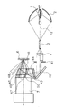
図5は、本発明の実施形態2に係る投写型表示装置の概略構成を示している。同図において、光源としてのランプ1、反射型ライトバルブ6、投写レンズ7は図1に示したものと同様である。また、凹面鏡2、ロッドプリズム3、コンデンサレンズ4、反射ミラー42、フールドレンズ43、及び全反射プリズム44によって構成される光学系を総称して照明光学系と呼ぶ。
(Embodiment 2)
FIG. 5 shows a schematic configuration of a projection display apparatus according to
凹面鏡2、ロッドプリズム3、コンデンサレンズ4の作用は、図1を用いて説明した実施形態の場合と同様であるので、その説明は省略する。本実施形態では、コンデンサレンズ4を出射した後の光が、反射ミラー42、フィールドレンズ43を経て全反射プリズム44に入射するように構成している。
The operations of the
ここで、全反射プリズム44の作用について説明する。全反射プリズム44は2つのプリズムから構成され、互いのプリズムの近接面には非常に薄い空気層45を形成している。空気層45は、照明光46が空気層45に入射する場合には臨界角以上の角度で入射して全反射されて反射型ライトバルブ6に斜め方向から入射し、ON光47は投写画像として臨界角以下の角度で空気層45に入射及び透過して投写レンズ7に入射するように角度設定されている。このように、全反射プリズム44を照明光学系の光路中に設けることにより、照明光学系をコンパクトに構成できる。
Here, the operation of the
反射型ライトバルブ6に入射した照明光46うち、白表示に相当するON光47は全反射プリズム44,投写レンズ7を透過してスクリーン上(図示せず)に拡大投写される。一方、黒表示に相当するOFF光48は投写レンズ7の有効径外に進行し、スクリーンには到達しない。
Of the
本実施形態の場合、反射型ライトバルブ6のカバーガラス界面で発生する第1の不要反射光49に加え、全反射プリズム44の反射型ライトバルブ6側の界面で発生する第2の不要反射光50が、いずれも投写画像のコントラスト性能に影響を及ぼす。この場合も、遮光部の面積が可変できる絞り41によって、投写レンズ7に入射する第1の不要反射光49と第2の不要反射光50の影響度合いを任意に可変できる。
In the case of this embodiment, in addition to the first unnecessary reflected light 49 generated at the cover glass interface of the reflective
絞り41の開口形状は実施形態1と同様に、図3に例示したものを用いることによって可変される。遮光部の可変による絞り又は開放は、実施形態1の場合と同様であり、遮光手段を基準位置から光軸12に向かう方向に移動開始させ、以後この移動開始の方向と同じ一方向に移動し続けることにより、遮光面積は増大し、絞り41の開口は、片側から順に遮光されることになる。また、遮光部が形成された状態において、逆方向に移動させると、遮光面積は減少し、絞り41の開口は一方向に開放して行くことになる。
The aperture shape of the
図6は、図5に示した実施形態の比較例に係る投写型表示装置の概略構成図を示している。図6に示した比較例では、絞り41が配置されていない構成、又は絞り41の開口が開放状態の構成である。この場合の照明光51は、反射型ライトバルブ6に入射した後、白表示に相当するON光52が全反射プリズム44、投写レンズ7を透過してスクリーン上(図示せず)に拡大投写される。一方、黒表示に相当するOFF光53は投写レンズ7の有効径外に進行し、スクリーンには到達しない。
FIG. 6 shows a schematic configuration diagram of a projection display apparatus according to a comparative example of the embodiment shown in FIG. In the comparative example shown in FIG. 6, the
また、第1の不要反射光54、及び第2の不要反射光55は、いずれも投写画像のコントラスト性能を劣化させる要因となる。図5の実施形態と、図6の比較例とを比較すると、図5では、絞り41を用いて固定絞りの開口の一部を遮光しているので、図5に示した第1の不要反射光49、及び第2の不要反射光50の光線束の太さが、図6に示した第1の不要反射光54、及び第2の不要反射光55の光線束よりも細くなっていることが分かる。
Further, the first unnecessary reflected light 54 and the second unnecessary reflected light 55 are factors that degrade the contrast performance of the projected image. Comparing the embodiment of FIG. 5 with the comparative example of FIG. 6, in FIG. 5, a part of the opening of the fixed diaphragm is shielded by using the
以上のように、図5の実施形態では、絞り41によって、第1の不要反射光49と第2の不要反射光50はいずれも、図6に示した比較例と比べ、効率的にカットすることができる。すなわち、回転対称に遮光面積を可変する絞り、例えば開口を同心円状に狭めて行く絞りに比べて、必要光の遮光を抑えることができるので、明るさの低下を最小限に抑えながら、コントラスト性能を向上させることができる。
As described above, in the embodiment of FIG. 5, both the first unnecessary reflected light 49 and the second unnecessary reflected light 50 are efficiently cut by the
また、絞り41の配置、遮光板の材質については、実施形態1と同様である。さらに、絞りの遮光面積をセットの外側からリモートコントロールで制御できるのが好ましいことや、映像信号に応じて遮光面積を制御できるのが好ましいことも実施形態1と同様である。また、絞り41の遮光面積の可変は、遮光手段を移動させる例で説明したが、図3Cの構成のように、遮光手段の開口が可変する構成でもよい。
The arrangement of the
(実施の形態3)
図7は、本発明の実施形態3に係る投写型表示装置の概略構成を示している。同図において、光源としてのランプ1、反射型ライトバルブ6、投写レンズ7は図1に示したものと同様である。また、図5と同様に、凹面鏡2,ロッドプリズム3,コンデンサレンズ4,反射ミラー42,フールドレンズ43,全反射プリズム44によって構成されるシステムを総称して照明光学系と呼ぶ。
(Embodiment 3)
FIG. 7 shows a schematic configuration of a projection display apparatus according to Embodiment 3 of the present invention. In the figure, a
凹面鏡2、ロッドプリズム3、コンデンサレンズ4の作用は、図1を用いて説明した実施形態の場合と同様であるので、その説明は省略する。本実施形態では、全反射プリズム44と反射型ライトバルブ6との間に色分解合成プリズム62を配置し、反射型ライトバルブ6を3つ用いている。
The operations of the
ここで色分解合成プリズム62の構成及び作用について、図8を参照して以下に説明する。図8は、図7に図示した色分解合成プリズム62の水平方向の断面図である。色分解合成プリズム62は、3つのプリズムからなり、それぞれのプリズムの近接面には第1のダイクロイックミラー71と第2のダイクロイックミラー72が形成されている。本実施形態で用いた色分解合成プリズム62の場合、全反射プリズム44から入射した光73が、まず第1のダイクロイックミラー71によって青色光のみ反射され青色光74となって青色用反射型ライトバルブ6Bに入射する。
Here, the configuration and operation of the color separation /
次に、第2のダイクロイックミラー72によって赤色光のみ反射され赤色光75となって赤色用反射型ライトバルブ6Rに入射する。そして、第1のダイクロイックミラー71と第2のダイクロイックミラー72のいずれをも透過した緑色光76は緑色用反射型ライトバルブ6Gに入射する。3色の光はそれぞれ対応する反射型ライトバルブ6B、6R、6Gによって反射された後、再び第1のダイクロイックミラー71と第2のダイクロイックミラー72によって1つに合成され、全反射プリズム44に入射する。
Next, only the red light is reflected by the second
このように、白色光を赤、青、緑の3原色に分解及び合成し、それぞれの映像信号に対応する3つの反射型ライトバルブ6B、6R、6Gを用いることで、高精細でフルカラーの投写画像を表示できる。図7に示した反射型ライトバルブ6に入射した照明光63うち、白表示に相当するON光64は色分解合成プリズム62,全反射プリズム44、投写レンズ7を透過してスクリーン上(図示せず)に拡大投写される。一方、黒表示に相当するOFF光65は投写レンズ7の有効径外に進行し、スクリーンには到達しない。
In this way, white light is decomposed and synthesized into the three primary colors of red, blue, and green, and three
本実施形態の場合、図1及び図5に示したような反射型ライトバルブ6のカバーガラス界面で発生する不要反射光や、図5に示した全反射プリズム44の反射型ライトバルブ6側界面で発生する不要反射光に加え(いずれも図7においては図示せず。)、色分解合成プリズムの界面で発生する不要反射光66も投写画像のコントラスト性能に影響を及ぼすことになる。
In the case of the present embodiment, unnecessary reflected light generated at the cover glass interface of the reflection type
この場合においても、遮光面積が可変できる絞り61によって、投写レンズ7に入射する不要反射光66の影響度合いを任意に可変できるようにしている。絞り61の開口形状は、前記実施形態1と同様に図3に例示したものを用いることにより可変され、遮光部の可変による絞り又は開放は、実施形態1の場合と同様であり、遮光手段を基準位置から光軸12に向かう方向に移動開始させ、以後この移動開始の方向と同じ一方向に移動し続けることにより、遮光面積は増大し、絞り61の開口は、片側から順に遮光されることになる。また、遮光部が形成された状態において、逆方向に移動させると、遮光面積は減少し、絞り61の開口は一方向に開放して行くことになる。
Even in this case, the degree of influence of the unnecessary reflected light 66 incident on the
図9は、図7に示した実施形態の比較例に係る投写型表示装置の概略構成図を示している。図9に示した比較例では、絞り61が配置されていない構成、又は絞りの開口が開放状態の構成である。この場合の照明光81は反射型ライトバルブ6に入射した後、白表示に相当するON光82が色分解合成プリズム62,全反射プリズム44,投写レンズ7を透過してスクリーン上(図示せず)に拡大投写される。
FIG. 9 shows a schematic configuration diagram of a projection display apparatus according to a comparative example of the embodiment shown in FIG. In the comparative example shown in FIG. 9, the
一方、黒表示に相当するOFF光83は投写レンズ7の有効径外に進行し、スクリーンには到達しない。また、不要反射光84は投写画像のコントラスト性能を劣化させる要因となる。
On the other hand, the OFF light 83 corresponding to black display travels outside the effective diameter of the
なお、図示していないが、この場合も反射型ライトバルブ6のカバーガラス界面で発生する不要反射光や全反射プリズム44の界面で発生する不要反射光は図1や図5に示した場合と同様の影響を及ぼす。
Although not shown in the drawing, unnecessary reflected light generated at the cover glass interface of the reflective
図7の実施形態と、図9の比較例とを比較すると、図7では、絞り61を用いて固定絞りの開口の一部を遮光しているので、図7に示した不要反射光66の光線束の太さが、図9に示した不要反射光84の光線束よりも細くなっていることが分かる。
The embodiment of FIG. 7, when comparing the comparative example of FIG. 9, FIG. 7, since the shielding part of the opening of the fixed throttle with a
以上のように、図7の実施形態では、絞り61によって、不要反射光66は図9に示した比較例と比べ、効率的にカットすることができる。すなわち、回転対称に遮光面積を可変する絞り、例えば開口を同心円状に狭めて行く絞りに比べて、必要光の遮光を抑えることができるので、明るさの低下を最小限に抑えながら、コントラスト性能を向上させることができる。
As described above, in the embodiment of FIG. 7, the unnecessary reflected light 66 can be efficiently cut by the
また、絞り61の配置、遮光板の材質については、実施形態1と同様である。さらに、絞りの遮光面積をセットの外側からリモートコントロールで制御できるのが好ましいことや、映像信号に応じて遮光面積を制御できるのが好ましいことも、実施形態1と同様である。また、絞り61の遮光面積の可変は、遮光手段を移動させる例で説明したが、図3Cの構成のように、遮光手段の開口が可変する構成でもよい。
Further, the arrangement of the
なお、前記各実施形態において、コントラスト性能と光出力とを任意に調整できるようにするため、絞りの遮光面積を可変できるように構成したが、絞りの開口が固定された構成とし、所望のコントラスト性能に固定して使用してもよい。この構成では、可動手段はなくてもよく、この場合の開口の形状は、図3の各図の例では、開放状態の開口から遮光部(斜線部)を除いた残りの開口の形状になる。 In each of the embodiments described above, the contrast performance and the light output can be arbitrarily adjusted so that the light-shielding area of the diaphragm can be varied. However, the diaphragm has a fixed aperture and has a desired contrast. You may use it fixed to performance. In this configuration, there is no need for movable means, and the shape of the opening in this case is the shape of the remaining opening obtained by removing the light-shielding portion (shaded portion) from the opening in the open state in the example of FIG. .
すなわち、固定した開口の形状は、開放状態に相当する開口に対して、略半円形状又は略三日月形状等の光軸に対して非回転対称の部分を遮光した形状と同じである。この場合、遮光部形状に相当する部分が光軸に対して非回転対称であるので、固定した開口の形状も光軸に対して非回転対称になる。 That is, the shape of the fixed opening is the same as the shape in which the non-rotationally symmetric part is shielded with respect to the optical axis such as a substantially semicircular shape or a substantially crescent shape with respect to the opening corresponding to the open state. In this case, since the portion corresponding to the shape of the light shielding portion is non-rotational symmetric with respect to the optical axis, the shape of the fixed opening is also non-rotational symmetric with respect to the optical axis.
また、前記各実施形態では、絞りの位置は、照明光学系の光路中において投写レンズの入射瞳と略共役な位置としたが、投写レンズの入射瞳に直接配置しても同様の効果が得られる。 In each of the above embodiments, the position of the stop is set to a position substantially conjugate with the entrance pupil of the projection lens in the optical path of the illumination optical system. It is done.
さらに、前記各実施形態で用いた絞りは、図11に示した反射型ライトバルブのように、映像信号に応じて光の進行方向を制御して光学像が形成されるライトバルブに対して最も大きな効果を発揮する。しかしながら、このような反射型ライトバルブに限るものではなく、画像形成面の出射側に透明なガラス又はプラスチックを有している反射型ライトバルブであれば、不要反射光を低減させるという効果が得られる。例えば、変調材料として液晶等を用いた光の偏光状態や回折状態、又は散乱状態の変化として光学像を形成するタイプのライトバルブを用いた場合でもよい。 Further, the diaphragm used in each of the above embodiments is most similar to the light valve in which an optical image is formed by controlling the traveling direction of light according to the video signal, like the reflective light valve shown in FIG. Demonstrate great effect. However, the present invention is not limited to such a reflection type light valve. If the reflection type light valve has transparent glass or plastic on the emission side of the image forming surface, an effect of reducing unnecessary reflected light can be obtained. It is done. For example, a light valve of a type that forms an optical image as a change in the polarization state, diffraction state, or scattering state of light using liquid crystal or the like as a modulation material may be used.
以上のように本発明によれば、遮光手段によって遮光された遮光部の形状を照明光学系の光軸に対して非回転対称とすることにより、必要光の遮光を抑えることができるので、明るさの低下を最小限に抑えながら、コントラスト性能を向上させることができ、ライトバルブ上に形成された光学像をスクリーン上に拡大投写する投写型表示装置に用いることができる。 As described above, according to the present invention, since the shape of the light-shielding portion shielded by the light-shielding means is non-rotationally symmetric with respect to the optical axis of the illumination optical system, the necessary light can be prevented from being shielded. The contrast performance can be improved while minimizing the decrease in height, and can be used in a projection display apparatus that enlarges and projects an optical image formed on a light valve on a screen.
1 ランプ
2 凹面鏡
3 ロッドプリズム
4 コンデンサレンズ
6 反射型ライトバルブ
7 投写レンズ
12 光軸
31,41,61 絞り
33,47,52,64,82 ON光
34,48,53,65,83 OFF光
35,49,50,54,55,66,84 不要反射光
44 全反射プリズム
62 色分解合成プリズム
DESCRIPTION OF
Claims (2)
画素毎に形成されたミラー素子を有する反射型ライトバルブと、
前記光源からの放射光を前記反射型ライトバルブ上に集光する照明光学系と、
前記放射光が前記反射型ライトバルブの前記ミラー素子によって反射された光をスクリーン上に拡大投写する投写レンズと、
前記投写レンズ中又は前記照明光学系中のいずれかの位置に配置され、前記投写レンズからスクリーン上に投写される光の光線束の断面積の大きさを決定する絞りとを備え、
前記絞りは、開口を有する固定絞りと、前記開口における光線束の一部を遮光可能な遮光板とで構成されており、
前記遮光板を前記照明光学系の光軸又は前記投写レンズの光軸に向かう方向へ変位可能に構成し、前記遮光板の変位により前記反射型ライトバルブの前面で反射された不要反射光のスクリーン上への投写を低減可能にしたことを特徴とする投写型表示装置。 A light source;
A reflective light valve having a mirror element formed for each pixel ;
An illumination optical system for collecting the emitted light from the light source on the reflective light valve;
A projection lens for enlarging and projecting the light reflected on the screen by the emitted light is the mirror element of the reflection type light valve,
A diaphragm that is arranged at any position in the projection lens or the illumination optical system, and that determines a size of a cross-sectional area of a light bundle of light projected on the screen from the projection lens,
The diaphragm is composed of a fixed diaphragm having an opening and a light shielding plate capable of shielding a part of the light beam in the opening,
A screen for unnecessary reflected light reflected on the front surface of the reflective light valve by the displacement of the light shielding plate, wherein the light shielding plate is configured to be displaceable in a direction toward the optical axis of the illumination optical system or the optical axis of the projection lens. A projection display device characterized in that projection on the top can be reduced .
Priority Applications (1)
| Application Number | Priority Date | Filing Date | Title |
|---|---|---|---|
| JP2003315509A JP3685794B2 (en) | 2001-04-25 | 2003-09-08 | Projection display |
Applications Claiming Priority (2)
| Application Number | Priority Date | Filing Date | Title |
|---|---|---|---|
| JP2001127910 | 2001-04-25 | ||
| JP2003315509A JP3685794B2 (en) | 2001-04-25 | 2003-09-08 | Projection display |
Related Parent Applications (1)
| Application Number | Title | Priority Date | Filing Date |
|---|---|---|---|
| JP2002586079A Division JP3484435B2 (en) | 2001-04-25 | 2002-04-23 | Projection display device |
Publications (3)
| Publication Number | Publication Date |
|---|---|
| JP2004029849A JP2004029849A (en) | 2004-01-29 |
| JP3685794B2 true JP3685794B2 (en) | 2005-08-24 |
| JP2004029849A5 JP2004029849A5 (en) | 2005-08-25 |
Family
ID=31189854
Family Applications (1)
| Application Number | Title | Priority Date | Filing Date |
|---|---|---|---|
| JP2003315509A Expired - Lifetime JP3685794B2 (en) | 2001-04-25 | 2003-09-08 | Projection display |
Country Status (1)
| Country | Link |
|---|---|
| JP (1) | JP3685794B2 (en) |
Cited By (1)
| Publication number | Priority date | Publication date | Assignee | Title |
|---|---|---|---|---|
| US8714752B2 (en) | 2010-08-23 | 2014-05-06 | Mitsubishi Electric Corporation | Projection display device |
Families Citing this family (6)
| Publication number | Priority date | Publication date | Assignee | Title |
|---|---|---|---|---|
| JP2005309337A (en) * | 2004-04-26 | 2005-11-04 | Fujinon Corp | Projection type image display device |
| JP4906042B2 (en) * | 2005-09-12 | 2012-03-28 | キヤノン株式会社 | Image projection optical unit and image projection apparatus |
| JP2007233004A (en) * | 2006-02-28 | 2007-09-13 | Sharp Corp | Projector |
| JP2007233003A (en) * | 2006-02-28 | 2007-09-13 | Sharp Corp | Projector |
| JP6626971B2 (en) * | 2016-06-29 | 2019-12-25 | マクセル株式会社 | Projection type video display |
| WO2023037729A1 (en) * | 2021-09-09 | 2023-03-16 | パナソニックIpマネジメント株式会社 | Projection image display device |
Family Cites Families (2)
| Publication number | Priority date | Publication date | Assignee | Title |
|---|---|---|---|---|
| JP4032658B2 (en) * | 2000-06-14 | 2008-01-16 | 三菱電機株式会社 | Projection display |
| JP4776785B2 (en) * | 2001-01-12 | 2011-09-21 | キヤノン株式会社 | Projection display |
-
2003
- 2003-09-08 JP JP2003315509A patent/JP3685794B2/en not_active Expired - Lifetime
Cited By (1)
| Publication number | Priority date | Publication date | Assignee | Title |
|---|---|---|---|---|
| US8714752B2 (en) | 2010-08-23 | 2014-05-06 | Mitsubishi Electric Corporation | Projection display device |
Also Published As
| Publication number | Publication date |
|---|---|
| JP2004029849A (en) | 2004-01-29 |
Similar Documents
| Publication | Publication Date | Title |
|---|---|---|
| US7033030B2 (en) | Projection-type display apparatus | |
| US7125123B2 (en) | Image projector | |
| JP2004258666A (en) | Projection display optical system | |
| JP4091632B2 (en) | Projection display optical system and projector including the projection display optical system | |
| JPWO2008132831A1 (en) | Projection display | |
| JPWO2007013564A1 (en) | Shutter device and driving method | |
| JP4282925B2 (en) | Projection display | |
| JP3182863B2 (en) | Projection display device | |
| JP3685794B2 (en) | Projection display | |
| JP4258293B2 (en) | Projection-type image display device | |
| JP2004258439A (en) | Projection type display device | |
| JP3557423B2 (en) | Projection display device | |
| JP2006023441A (en) | Image display apparatus | |
| JP2005301069A (en) | Projection-type display device | |
| JP4229747B2 (en) | Rod integrator and lighting device using the same | |
| JP2002082386A (en) | Projection-type display device | |
| JP2007233003A (en) | Projector | |
| JP2005202366A (en) | Image display apparatus | |
| US20090040395A1 (en) | Image display apparatus | |
| JP4574132B2 (en) | Illumination device and color image display device using the same | |
| JP2003177352A (en) | Projection type display device and back projection type display device using the same | |
| JP2008145666A (en) | Illuminating device and image projection apparatus using same | |
| JP2007286391A (en) | Illuminating device, illuminating method and projection type display apparatus using illuminating device | |
| JP2006065057A (en) | Light source device for projector | |
| JP2006084989A (en) | Projection optical system and projection device |
Legal Events
| Date | Code | Title | Description |
|---|---|---|---|
| A521 | Request for written amendment filed |
Free format text: JAPANESE INTERMEDIATE CODE: A523 Effective date: 20050420 |
|
| A621 | Written request for application examination |
Free format text: JAPANESE INTERMEDIATE CODE: A621 Effective date: 20050420 |
|
| A871 | Explanation of circumstances concerning accelerated examination |
Free format text: JAPANESE INTERMEDIATE CODE: A871 Effective date: 20050420 |
|
| TRDD | Decision of grant or rejection written | ||
| A975 | Report on accelerated examination |
Free format text: JAPANESE INTERMEDIATE CODE: A971005 Effective date: 20050523 |
|
| A01 | Written decision to grant a patent or to grant a registration (utility model) |
Free format text: JAPANESE INTERMEDIATE CODE: A01 Effective date: 20050526 |
|
| A61 | First payment of annual fees (during grant procedure) |
Free format text: JAPANESE INTERMEDIATE CODE: A61 Effective date: 20050531 |
|
| R150 | Certificate of patent or registration of utility model |
Ref document number: 3685794 Country of ref document: JP Free format text: JAPANESE INTERMEDIATE CODE: R150 Free format text: JAPANESE INTERMEDIATE CODE: R150 |
|
| FPAY | Renewal fee payment (event date is renewal date of database) |
Free format text: PAYMENT UNTIL: 20080610 Year of fee payment: 3 |
|
| FPAY | Renewal fee payment (event date is renewal date of database) |
Free format text: PAYMENT UNTIL: 20090610 Year of fee payment: 4 |
|
| FPAY | Renewal fee payment (event date is renewal date of database) |
Free format text: PAYMENT UNTIL: 20100610 Year of fee payment: 5 |
|
| FPAY | Renewal fee payment (event date is renewal date of database) |
Free format text: PAYMENT UNTIL: 20100610 Year of fee payment: 5 |
|
| FPAY | Renewal fee payment (event date is renewal date of database) |
Free format text: PAYMENT UNTIL: 20110610 Year of fee payment: 6 |
|
| FPAY | Renewal fee payment (event date is renewal date of database) |
Free format text: PAYMENT UNTIL: 20120610 Year of fee payment: 7 |
|
| FPAY | Renewal fee payment (event date is renewal date of database) |
Free format text: PAYMENT UNTIL: 20130610 Year of fee payment: 8 |
|
| EXPY | Cancellation because of completion of term |