JP3679701B2 - Image forming apparatus - Google Patents
Image forming apparatus Download PDFInfo
- Publication number
- JP3679701B2 JP3679701B2 JP2000323635A JP2000323635A JP3679701B2 JP 3679701 B2 JP3679701 B2 JP 3679701B2 JP 2000323635 A JP2000323635 A JP 2000323635A JP 2000323635 A JP2000323635 A JP 2000323635A JP 3679701 B2 JP3679701 B2 JP 3679701B2
- Authority
- JP
- Japan
- Prior art keywords
- sheet
- image forming
- forming apparatus
- unit
- processing
- Prior art date
- Legal status (The legal status is an assumption and is not a legal conclusion. Google has not performed a legal analysis and makes no representation as to the accuracy of the status listed.)
- Expired - Lifetime
Links
Images


Description
【0001】
【発明の属する技術分野】
本発明は、複写機やプリンタ等の画像形成装置に関するものであり、特に画像読取部と画像形成部との間、あるいは画像形成部の上方にシート排出空間を有する画像形成装置に関する。
【0002】
【従来の技術】
近年、複写機のデジタル化によって、図6(a)に示すように、画像読取部100と画像形成部101との間に、シートを排出する排出空間部102を設置した、いわゆる機内排出型の複写機が発明されている。従来、装置の側方に突出していた排出トレイ等を画像読取部100と画像形成部101との間に配置したことにより、複写機の占有面積を飛躍的に減少させることができる。
【0003】
また、シートの両面に画像を形成する場合、排出空間部102を利用してシートの向きを反転させることが可能となった。具体的には、図6(b)に示すように、画像形成手段103によって片面に画像が形成されたシートを、一旦、排出ローラ104によって排出空間部102に排出し始める。続いて、所定の位置で排出ローラ104を逆転させてシートを再度装置内に引き込む。そして、再給送路105を経由して再度画像形成手段103へ搬送して反対側の面に画像を形成し、再び排出ローラ104によって、排出空間部102に積載するよう、排出する動作を行なうわけである。
【0004】
上記構成を採用することで、従来必要としていた反転部等の構成を省略することができるようになり、さらなる小型化や低コスト化を実現することができた。
【0005】
【発明が解決しようとする課題】
しかしながら最近では、省スペースと高生産性を両立するために、図7に示すように、排出空間部102にステイプル処理やソート処理等を行なう処理装置106を配置することが考え出されている。従来の技術で述べた反転可能な複写機の機内排出空間部102に処理装置106を設ける場合、本体側の排出ローラ104から排出されたシートを受け取り、ステイプルなどの処理部106aに搬送する搬送ローラ106bやガイド106c等が必要となる。
【0006】
処理装置106が装着された複写機において、従来どおり排出ローラ104を逆転させてシートを反転させようとすると、前述したように、従来の画像形成装置は両面記録時の反転時には、片面記録されたシートの後端が排出口から突出して再び、画像形成装置内に搬送されていくような動作をするために、積載満載高さ規制値を、両面反転したシートがすでに積載されたシートを押し出してしまわないように、積載保証高さを余裕を持って低めに設定しなければならない。また、一度出たシートが再び本体内に入っていく様子が使用者に違和感をもたれるなどの欠点を伴う。
【0007】
さらに、従来例において、処理装置106を設置した状態で両面記録時の反転動作は、長尺シートの端部が、処理装置106の受け取り部に進入し、ひいては、処理装置の搬送ローラ106bのニップを通過して反転するようになる。
【0008】
よって、搬送ローラ106bの制御にステッピングモータを用いている場合、画像形成装置本体の排出ローラ104とコントローラが違うために適正な同期をとることが出来ないため、座屈、脱調等を生ずるおそれがある。これを防止するために、処理装置106の搬送ローラ106bのニップを解除する機構を新たに付け加える必要がある。
【0009】
これらを防止しようとすると、本体側の排出ローラ104と処理装置の搬送ローラ106bとの距離を大きくとる、換言すれば、排出空間部102の排出ローラ104と処理装置106との距離を大きくとる必要が生じる。しかし、処理装置106を排出ローラ104から遠ざけると、処理装置106が複写機本体からはみ出してしまい、省スペース化という目的を達成することができない。
【0010】
また、搬送ローラ106bのニップ解除のための機構などが追加されることでも、装置の大型化やコストアップという課題が生じてしまう。
【0011】
本発明は、以上の課題に鑑みなされたものであり、その目的は、機内排出型画像形成装置において、排出空間部に処理装置を設置しようとした場合の課題を解決し、省スペース化とユーザビリティを達成した画像形成装置を提供するものである。
【0012】
【課題を解決するための手段】
上記目的を達成するための本発明に係る代表的な構成は、画像読取部と画像形成部との間に、シートを排出する空間部を設けた画像形成装置において、シートに所定の処理を行う後処理部と、シートを受け取り前記後処理部へ搬送するシート受け取り部と、前記シート受け取り部と異なるパスであってシートを進入させて該シートを反転させるための搬送手段を有しない反転パスと、を備えた処理装置を前記空間部に設けたことを特徴とする。
【0013】
【発明の実施の形態】
〔第1実施形態〕
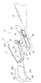
図1乃至図5を参照して本発明の第1実施形態に係る画像形成装置について説明する。尚、図1及び図2は画像形成装置の要部断面説明図であり、図3はシート処理装置を装着する状態説明図、図4はシート処理装置の構成説明図であり、図5は側面カバーを開いた状態説明図である。
【0014】
{全体構成}
まず、画像形成装置の全体構成について説明する。図1に示すように、この画像形成装置は画像読取部Aと、画像形成部Bとの間にシート排出用の空間部Cが形成されている。
【0015】
画像読取部Aは原稿読取手段1の上方に原稿給送手段2を取り付けたものであり、原稿給送手段2から1枚ずつ供給した原稿を原稿読取手段1によって光学的に読み取り、これを光電変換してデジタル信号として画像形成部Bへ送るものである。
【0016】
画像形成部Bは装置下部に画像形成用のシート束をセットしておくシートカセット3が装填されており、このシートカセット3内の最上位のシートをピックアップローラ4で給送するとともに、分離ローラ対5によって1枚ずつに分離給送し、搬送ローラ6で画像形成手段7へと搬送する。
【0017】
本実施形態では画像形成手段7として、感光体ドラム7aに図示しない現像器によってトナー像を形成し、このトナー像を搬送されたシートに転写記録する電子写真記録方式を用いている。このときにシートに転写される画像は、画像読取部Aで読み取った後でデジタル処理された画像信号、または、外部のパソコンなどから送られた画像信号で、レーザービームの発光タイミング決定し、感光体ドラム表面に、図示せぬレーザースキャナーユニットからレーザービームを照射して形成した潜像を現像器で反転現像したものである。
【0018】
画像形成されたシートは定着部8に搬送され、熱及び圧力が印加されて画像が定着される。そして、そのシートは切換フラッパ9によって上方へ導かれ、搬送ローラ10及び排出ローラ11によって排出口12から空間部Cに形成された排出トレイ部13へ排出する。尚、前記排出トレイ部13は画像形成部Bの上カバーも兼ねている。
【0019】
本実施形態に係る画像形成装置はシートの両面に記録が可能となっており、両面記録を行う場合には前述の如くして片面記録されたシートが排出途中でスイッチバック搬送されて両面搬送部14へと搬送され、片面記録の場合と同様にして再度画像形成手段7へと搬送される。そして、第二面(片面記録されたシートの記録されていない側の面)に画像記録されて排出トレイ部13へと排出される。このため、前記搬送ローラ10 は正逆回転が切り換え可能になっている。
【0020】
{シート処理装置}
本実施形態の画像形成装置は排出されるシート束にステイプル処理等を行うための処理装置Dが前記空間部Cに設けられている。この処理装置Dは、図3に示すように、装置前部(使用者が操作する側)から矢印方向へ設置される。
【0021】
この処理装置Dは、図1に示すように、処理装置前部に前カバー15が設けられており、図示せぬステイプル用の針の交換口などが覆われている。後処理に際しては、画像形成部Bの排出ローラ11を含む排出部16から排出されるシートを、搬送ローラ31を含むシート受け取り部17で受け取り、後処理部18においてステイプル処理等の後処理を行った後、処理装置Dの積載トレイ19へと排出する。
【0022】
前記処理装置Dの構成について、更に具体的に説明すると、図4に示すように、シート受け取り部17には搬送ローラ31へと排出されるシートをガイドするシート搬送ガイド20が設けられており、このシート搬送ガイド20の下面は排出されるシートの上面側をガイドする上ガイド部20aとなっている。また、シート搬送ガイド20の下方には排出されるシートの下面側をガイドする下ガイド部21aを形成する支持部材21が設けられ、上記上ガイド部20aと下ガイド部21aによって排出パスが形成されている。尚、前記シート搬送ガイド20はジャム(シート詰まり)処理のために図4の矢印a方向に回動可能であり、このとき使用者がシート搬送ガイド20を持ち上げるための把手部20bが設けられている。
【0023】
ここで、図5にジャム処理の状態を示す。使用者が装置左側面に設けられた側面ドア27(図3参照)を開くことで、処理装置Dのシート受け取り部17のシート搬送ガイド20を開くための把手部20bに容易にアクセスできることがわかる。
【0024】
搬送ローラ31によって束押しベルト部25上に排出されたシートは、図4の一点鎖線に示す軌跡のように回転する戻し部材23によって図示しないストッパー部に押しつけられ、これによってシート束の搬送方向が整合される。一方、シート束の幅方向(搬送方向と直交する方向)の整合はサイドガイド24によって行われる。すなわち、シート幅方向両側には排出シートを挟み込むよう一対のサイドガイド24が配置されている。このサイドガイド24の一方が図示しない駆動機構によりシート幅方向に動くようになっており、排出シートを他方のサイドガイドとの間に挟み込み、これによってシート束の幅方向の整合が行われる。
【0025】
整合されたシート束は後処理部18でシフトやステイプル等の後処理が行われ、束押しベルト部25によって積載トレイ19へ順次送り込まれる。束押しベルト部25にはシート束を積載トレイ19に押し出すための押し出し爪26が設けられている。
【0026】
ここで、シート処理装置Dの駆動制御は、設計の自由度、コスト、汎用性などの関係から独自のコントローラCPUを内蔵して行う。よって、装置本体側からはタイミングを取るための信号出力を受け取るだけの関係となっている。
【0027】
{反転パス}
次に図1、図2及び図4を参照してシートに両面記録を行うときの反転パスについて説明する。
【0028】
前記処理装置Dのシート搬送ガイド20よりもシート搬送方向上流側に、搬送されるシートをガイドするシートガイド部材22が設けられている。このシートガイド部材22はシート排出と反転搬送とのシート搬送方向を切り換えるフラッパとしても機能するものであり、軸28を中心に図示しないソレノイド等の駆動機構によって回動可能になっている。
【0029】
片面記録の場合には、図4に示すように、前記シートガイド部材22の下面が排出されるシートの上面側をガイドする上ガイド部22aとなり、シート下面側をガイドする支持部材21とによって排出パスが形成される。この排出パスを通過したシートはシート搬送ガイド20と支持部材21とでガイドされて搬送ローラ31によって搬送される。
【0030】
一方、両面記録を行うときは、図2に示すように、前記シートガイド部材22を所定量だけ反時計回り方向へ回転させる。このときシートガイド部材22の上面がシートの下面側をガイドする下ガイド部22bとなり、シートガイド部材22と上ガイド部材29とによって反転パスが形成される。この状態で片面記録が行われたシートを搬送ローラ10 によって搬送すると、シートはシートガイド部材22の下ガイド部22bによってシート下面側がガイドされるとともに、上ガイド部材29によってシート上面側がガイドされて反転パスに入り込み、シート搬送ガイド20の把手部20bにシート下面がガイドされて処理装置Dの上方へ案内される。よって、前記把手部20bは反転パスにおけるシートの下ガイド部も兼ねている。
【0031】
前記反転パスはシートガイド部材22の回転によって処理装置Dの上方に形成され、該部分は前カバー15によって覆われているため、シートが排出ローラ11から所定量突出しても装置外部に露出することはない。
【0032】
そして、反転パスを所定量(シート後端が切換フラッパ9を通過するまで)搬送されたシートは反転搬送されて両面搬送部14へと搬送されていく。
【0033】
上記のように、反転パスを処理装置D、具体的には搬送ローラ31の上方に形成することにより、搬送ローラ31を逆転駆動し、あるいは搬送ローラ31によるシートニップを解除する機構を設ける必要がなくなり、排出ローラ11と処理装置の搬送ローラ31との距離を大きくとる必要もない。このため、装置の省スペース化とユーザビリティが達成される。
【0034】
また、反転搬送するときに反転させるシートを装置外部に出ないようにガイドするため、使用者が間違って触ったり、引っ張るなどの不具合等を避けることができる。
【0035】
なお、上述した第1実施形態の画像形成装置では、装置の最上部に画像読取部が設けられているが、本発明はこれに限らず、画像読取部にあたるものがないプリンタタイプの画像形成装置であっても、処理装置の上方でシートを反転させる構成とすることにより、上述した実施の形態での画像形成装置と、同様の効果があることは明白である。このとき、反転させるシートが外部に露出しないような構成を有してもよい。また、画像読取部の代わりに、テーブル状の板状部材(天板)を設けたプリンタにおいても有効である。
【0036】
【発明の効果】
本発明は前述したように構成したために、装置を大型化、複雑化することなくシートの反転搬送が可能であり、また反転時に装置外部にシートの先端が飛び出さないために、使用者に違和感を与えるともない。
【図面の簡単な説明】
【図1】 画像形成装置の要部断面説明図である。
【図2】 反転搬送する画像形成装置の要部断面説明図である。
【図3】 シート処理装置を装着する状態説明図である。
【図4】 シート処理装置の構成説明図である。
【図5】 側面カバーを開いた状態説明図である。
【図6】 従来技術に係る画像形成装置の説明図である。
【図7】 シート処理装置を設けた従来技術に係る画像形成装置の説明図である。
【符号の説明】
A …画像読取部
B …画像形成部
C …空間部
D …処理装置
1 …原稿読取手段
2 …原稿給送手段
3 …シートカセット
4 …ピックアップローラ
5 …分離ローラ対
6 …搬送ローラ
7 …画像形成手段
7a …感光体ドラム
8 …定着部
9 …切換フラッパ
10 …搬送ローラ
11 …排出ローラ
12 …排出口
13 …排出トレイ部
14 …両面搬送部
15 …前カバー
16 …排出部
17 …シート受け取り部
18 …後処理部
19 …積載トレイ
20 …シート搬送ガイド
20a …上ガイド部
20b …把手部
21 …支持部材
21a …下ガイド部
22 …シートガイド部材
22a …上ガイド部
22b …下ガイド部
23 …戻し部材
24 …サイドガイド
25 …束押しベルト部
26 …押し出し爪
27 …側面ドア
28 …軸
29 …上ガイド部材
31 …搬送ローラ[0001]
BACKGROUND OF THE INVENTION
The present invention relates to an image forming apparatus such as a copying machine or a printer, and more particularly to an image forming apparatus having a sheet discharge space between an image reading unit and an image forming unit or above an image forming unit.
[0002]
[Prior art]
Recently, digitization of the copying machine, as shown in FIG. 6 (a), between the
[0003]
Further, when images are formed on both sides of a sheet, it is possible to reverse the direction of the sheet using the
[0004]
By adopting the above-described configuration, it is possible to omit the configuration of the reversing unit and the like that have been conventionally required, and further downsizing and cost reduction can be realized.
[0005]
[Problems to be solved by the invention]
Recently, however, in order to achieve both space saving and high productivity, as shown in FIG. 7, it has been devised to place the
[0006]
In a copying machine equipped with the
[0007]
Further, in the conventional example, the reversal operation during double-sided recording with the
[0008]
Therefore, when a stepping motor is used to control the
[0009]
In order to prevent these, it is necessary to increase the distance between the
[0010]
In addition, the addition of a mechanism for releasing the nip of the conveying
[0011]
The present invention has been made in view of the above problems, and an object of the present invention is to solve the problems in the case where a processing apparatus is installed in the discharge space portion in the in-machine discharge type image forming apparatus, thereby saving space and improving usability. An image forming apparatus that achieves the above is provided.
[0012]
[Means for Solving the Problems]
In order to achieve the above object, a typical configuration according to the present invention performs predetermined processing on a sheet in an image forming apparatus in which a space for discharging the sheet is provided between the image reading unit and the image forming unit. A post-processing unit, a sheet receiving unit that receives a sheet and conveys the sheet to the post-processing unit, and a reversing path that is different from the sheet receiving unit and does not have a conveying unit for reversing the sheet by entering the sheet Are provided in the space portion .
[0013]
DETAILED DESCRIPTION OF THE INVENTION
[First Embodiment]
An image forming apparatus according to a first embodiment of the present invention will be described with reference to FIGS. 1 and 2 are cross-sectional explanatory views of the main part of the image forming apparatus, FIG. 3 is a state explanatory view of the sheet processing apparatus, FIG. 4 is a configuration explanatory view of the sheet processing apparatus, and FIG. It is state explanatory drawing which opened the cover.
[0014]
{overall structure}
First, the overall configuration of the image forming apparatus will be described. As shown in FIG. 1, in this image forming apparatus, a sheet discharge space C is formed between an image reading unit A and an image forming unit B.
[0015]
The image reading unit A has a document feeding unit 2 attached above the document reading unit 1. The document reading unit 1 optically reads the documents supplied one by one from the document feeding unit 2 and photoelectrically reads them. This is converted and sent to the image forming unit B as a digital signal.
[0016]
The image forming unit B is loaded with a
[0017]
In this embodiment, an electrophotographic recording system is used as the image forming means 7 in which a toner image is formed on the photosensitive drum 7a by a developing unit (not shown), and this toner image is transferred and recorded on the conveyed sheet. The image transferred to the sheet at this time is determined by the laser beam emission timing based on the image signal digitally processed after being read by the image reading unit A or the image signal sent from an external personal computer or the like. A latent image formed by irradiating a laser beam from a laser scanner unit (not shown) on the surface of the body drum is reversely developed by a developing device.
[0018]
The sheet on which the image has been formed is conveyed to the fixing
[0019]
The image forming apparatus according to the present embodiment is capable of recording on both sides of a sheet. When performing double-sided recording, the sheet recorded on one side as described above is switchback-conveyed in the middle of discharge, and a duplex conveying unit. is conveyed to 14, it is conveyed to the image forming unit 7 again in the same manner as in the case of single-sided printing. Then, is discharged to the second surface is an image recorded on the (side recorded surface of the unrecorded side of sheets) with a
[0020]
{Sheet processing device}
In the image forming apparatus of the present embodiment, a processing device D for performing a stapling process or the like on the discharged sheet bundle is provided in the space C. As shown in FIG. 3, the processing device D is installed in the direction of the arrow from the front of the device (side operated by the user).
[0021]
As shown in FIG. 1, the processing apparatus D is provided with a
[0022]
The configuration of the processing apparatus D will be described more specifically. As shown in FIG. 4, the
[0023]
Here, FIG. 5 shows the state of the jam processing. It can be seen that the user can easily access the
[0024]
The sheet discharged onto the bundle pressing
[0025]
The aligned sheet bundle is subjected to post-processing such as shifting and stapling in the
[0026]
Here, the drive control of the sheet processing apparatus D is performed by incorporating a unique controller CPU in view of the degree of design freedom, cost, versatility, and the like. Therefore, the relationship is such that only a signal output for taking timing is received from the apparatus main body side.
[0027]
{Reverse path}
Next, with reference to FIG. 1, FIG. 2 and FIG. 4, a reversal pass when performing duplex recording on a sheet will be described.
[0028]
A
[0029]
In the case of single-sided recording, as shown in FIG. 4, the lower surface of the
[0030]
On the other hand, when performing duplex recording, as shown in FIG. 2, the
[0031]
The reversing path is formed above the processing apparatus D by the rotation of the
[0032]
Then, the sheet conveyed through a reversing path by a predetermined amount (until the trailing edge of the sheet passes through the switching flapper 9) is reversed and conveyed to the double-
[0033]
As described above, it is necessary to provide a mechanism that reversely drives the
[0034]
In addition, since the sheet to be reversed is guided so as not to come out of the apparatus during reversal conveyance, problems such as a mistaken touch or pulling by the user can be avoided.
[0035]
In the image forming apparatus of the first embodiment form state described above, the top is an upper image reader is provided, the present invention is not limited thereto, the image forming of the printer type is not one corresponding to an image reading portion of the device Even in the case of the apparatus, it is obvious that the configuration in which the sheet is reversed above the processing apparatus has the same effect as the image forming apparatus in the above-described embodiment. At this time, the sheet to be reversed may be configured not to be exposed to the outside. Further, it is also effective in a printer provided with a table-like plate member (top plate) instead of the image reading unit.
[0036]
【The invention's effect】
Since the present invention is configured as described above, the sheet can be reversed and conveyed without increasing the size and complexity of the apparatus, and the leading edge of the sheet does not jump out of the apparatus during the reversal. Also give.
[Brief description of the drawings]
FIG. 1 is an explanatory cross-sectional view of a main part of an image forming apparatus.
FIG. 2 is an explanatory cross-sectional view of a main part of an image forming apparatus that is reversed and conveyed.
FIG. 3 is an explanatory diagram of a state in which the sheet processing apparatus is mounted.
FIG. 4 is a configuration explanatory diagram of a sheet processing apparatus.
FIG. 5 is an explanatory view showing a state in which a side cover is opened.
FIG. 6 is an explanatory diagram of an image forming apparatus according to a conventional technique.
FIG. 7 is an explanatory diagram of a conventional image forming apparatus provided with a sheet processing apparatus.
[Explanation of symbols]
A ... Image reading section B ... Image forming section C ... Space section D ... Processing device 1 ... Document reading means 2 ... Document feeding means 3 ...
10… Conveying roller
11… discharge roller
12… discharge port
13… discharge tray
14… Double-sided conveyance section
15… Front cover
16… discharge section
17… Sheet receiving part
18 Post-processing section
19… Loading tray
20 ... Sheet conveyance guide
20a ... Upper guide part
20b ... handle part
21… Support member
21a ... Lower guide part
22… Sheet guide member
22a ... Upper guide part
22b ... Lower guide part
23… Return member
24… Side guide
25… Bundle push belt
26… extruded nails
27… Side door
28… axis
29… Upper guide member
31… Conveying roller
Claims (6)
シートに所定の処理を行う後処理部と、シートを受け取り前記後処理部へ搬送するシート受け取り部と、前記シート受け取り部と異なるパスであってシートを進入させて該シートを反転させるための搬送手段を有しない反転パスと、を備えた処理装置を前記空間部に設けたことを特徴とする画像形成装置。In the image forming apparatus provided with a space for discharging the sheet between the image reading unit and the image forming unit,
A post-processing unit that performs a predetermined process on the sheet, a sheet receiving unit that receives the sheet and conveys the sheet to the post-processing unit, and conveyance for reversing the sheet by entering the sheet in a different path from the sheet receiving unit An image forming apparatus comprising: a processing device including a reversing path having no means provided in the space portion .
シートに所定の処理を行う後処理部と、シートを受け取り前記後処理部へ搬送するシート受け取り部と、前記シート受け取り部と異なるパスであってシートを進入させて該シートを反転させるための搬送手段を有しない反転パスと、を備えた処理装置を前記空間部に設けたことを特徴とする画像形成装置。In the image forming apparatus provided with a space part for discharging the sheet above the image forming part,
A post-processing unit that performs a predetermined process on the sheet, a sheet receiving unit that receives the sheet and conveys the sheet to the post-processing unit, and conveyance for reversing the sheet by entering the sheet in a different path from the sheet receiving unit An image forming apparatus comprising: a processing device including a reversing path having no means provided in the space portion .
Priority Applications (7)
| Application Number | Priority Date | Filing Date | Title |
|---|---|---|---|
| JP2000323635A JP3679701B2 (en) | 2000-10-24 | 2000-10-24 | Image forming apparatus |
| US09/973,839 US6647243B2 (en) | 2000-10-16 | 2001-10-11 | Sheet treating apparatus, method of mounting sheet treating apparatus, and image forming apparatus |
| CNB011425814A CN100394326C (en) | 2000-10-16 | 2001-10-16 | Paper processing apparatus, method for installing said apparatus and imaging device |
| KR10-2001-0063593A KR100421405B1 (en) | 2000-10-16 | 2001-10-16 | Sheet treating apparatus, method of mounting sheet treating apparatus, and image forming apparatus |
| US10/614,223 US7120383B2 (en) | 2000-10-16 | 2003-07-08 | Sheet treating apparatus, method of mounting sheet treating apparatus, and image forming apparatus |
| US11/260,195 US7050752B2 (en) | 2000-10-16 | 2005-10-28 | Sheet treating apparatus, method of mounting sheet treating apparatus, and image forming apparatus |
| US11/374,097 US7107006B1 (en) | 2000-10-16 | 2006-03-14 | Sheet treating apparatus, method of mounting sheet treating apparatus, and image forming apparatus |
Applications Claiming Priority (1)
| Application Number | Priority Date | Filing Date | Title |
|---|---|---|---|
| JP2000323635A JP3679701B2 (en) | 2000-10-24 | 2000-10-24 | Image forming apparatus |
Publications (2)
| Publication Number | Publication Date |
|---|---|
| JP2002128355A JP2002128355A (en) | 2002-05-09 |
| JP3679701B2 true JP3679701B2 (en) | 2005-08-03 |
Family
ID=18801279
Family Applications (1)
| Application Number | Title | Priority Date | Filing Date |
|---|---|---|---|
| JP2000323635A Expired - Lifetime JP3679701B2 (en) | 2000-10-16 | 2000-10-24 | Image forming apparatus |
Country Status (1)
| Country | Link |
|---|---|
| JP (1) | JP3679701B2 (en) |
Cited By (1)
| Publication number | Priority date | Publication date | Assignee | Title |
|---|---|---|---|---|
| US8606169B2 (en) | 2009-05-07 | 2013-12-10 | Canon Kabushiki Kaisha | Image forming apparatus with movable upper unit to access a sheet conveyance path |
Families Citing this family (2)
| Publication number | Priority date | Publication date | Assignee | Title |
|---|---|---|---|---|
| JP4152961B2 (en) | 2005-02-28 | 2008-09-17 | シャープ株式会社 | Image forming apparatus |
| JP6716934B2 (en) * | 2016-02-03 | 2020-07-01 | コニカミノルタ株式会社 | Paper post-processing device and image forming system including paper post-processing device |
-
2000
- 2000-10-24 JP JP2000323635A patent/JP3679701B2/en not_active Expired - Lifetime
Cited By (1)
| Publication number | Priority date | Publication date | Assignee | Title |
|---|---|---|---|---|
| US8606169B2 (en) | 2009-05-07 | 2013-12-10 | Canon Kabushiki Kaisha | Image forming apparatus with movable upper unit to access a sheet conveyance path |
Also Published As
| Publication number | Publication date |
|---|---|
| JP2002128355A (en) | 2002-05-09 |
Similar Documents
| Publication | Publication Date | Title |
|---|---|---|
| US7284752B2 (en) | Jam disposer for sheet post-processing device | |
| JP4516894B2 (en) | Automatic document feeder, image forming apparatus having the same, and image reading apparatus | |
| US6725011B2 (en) | Image forming apparatus provided with a reverse discharging portion | |
| JP4867294B2 (en) | Image processing device | |
| JP3215811B2 (en) | Document reading device | |
| JP5498912B2 (en) | Image forming apparatus | |
| US4954849A (en) | Copying apparatus operable in a two-side copy mode | |
| JP2003333274A (en) | Document feeder and image forming device equipped with the same | |
| JP4097659B2 (en) | Paper feed structure of image forming apparatus | |
| JP4477740B2 (en) | Sheet conveying apparatus and image reading apparatus | |
| JP3679701B2 (en) | Image forming apparatus | |
| JPH06324540A (en) | Copying machine equipped with automatic document feeding device | |
| JP3445966B2 (en) | Automatic double-sided apparatus and image forming apparatus equipped with the automatic double-sided apparatus | |
| JP2826124B2 (en) | Sheet transport device | |
| JP4549151B2 (en) | Image forming apparatus | |
| JP2819305B2 (en) | Sheet transport device | |
| JPH06138734A (en) | Automatic document feeder | |
| JP3332710B2 (en) | Sheet stacking apparatus and image forming apparatus | |
| JP2003252516A (en) | Sheet handling device and image forming device | |
| JP4227473B2 (en) | Image forming apparatus | |
| JP2003298811A (en) | Image reader and image reader/recorder provided the same | |
| JP3610126B2 (en) | Sheet post-processing apparatus and image forming apparatus having the same | |
| JP4018036B2 (en) | Image forming apparatus provided with sheet post-processing apparatus | |
| JP4250042B2 (en) | Image reading apparatus and image recording apparatus | |
| JP2013249198A (en) | Sheet conveying device, and image reading device and image forming apparatus using the same |
Legal Events
| Date | Code | Title | Description |
|---|---|---|---|
| A977 | Report on retrieval |
Free format text: JAPANESE INTERMEDIATE CODE: A971007 Effective date: 20040621 |
|
| A131 | Notification of reasons for refusal |
Free format text: JAPANESE INTERMEDIATE CODE: A131 Effective date: 20040629 |
|
| A521 | Written amendment |
Free format text: JAPANESE INTERMEDIATE CODE: A523 Effective date: 20040827 |
|
| TRDD | Decision of grant or rejection written | ||
| A01 | Written decision to grant a patent or to grant a registration (utility model) |
Free format text: JAPANESE INTERMEDIATE CODE: A01 Effective date: 20050426 |
|
| A61 | First payment of annual fees (during grant procedure) |
Free format text: JAPANESE INTERMEDIATE CODE: A61 Effective date: 20050513 |
|
| R150 | Certificate of patent or registration of utility model |
Ref document number: 3679701 Country of ref document: JP Free format text: JAPANESE INTERMEDIATE CODE: R150 Free format text: JAPANESE INTERMEDIATE CODE: R150 |
|
| FPAY | Renewal fee payment (event date is renewal date of database) |
Free format text: PAYMENT UNTIL: 20090520 Year of fee payment: 4 |
|
| FPAY | Renewal fee payment (event date is renewal date of database) |
Free format text: PAYMENT UNTIL: 20100520 Year of fee payment: 5 |
|
| FPAY | Renewal fee payment (event date is renewal date of database) |
Free format text: PAYMENT UNTIL: 20100520 Year of fee payment: 5 |
|
| FPAY | Renewal fee payment (event date is renewal date of database) |
Free format text: PAYMENT UNTIL: 20110520 Year of fee payment: 6 |
|
| FPAY | Renewal fee payment (event date is renewal date of database) |
Free format text: PAYMENT UNTIL: 20120520 Year of fee payment: 7 |
|
| FPAY | Renewal fee payment (event date is renewal date of database) |
Free format text: PAYMENT UNTIL: 20120520 Year of fee payment: 7 |
|
| FPAY | Renewal fee payment (event date is renewal date of database) |
Free format text: PAYMENT UNTIL: 20130520 Year of fee payment: 8 |
|
| FPAY | Renewal fee payment (event date is renewal date of database) |
Free format text: PAYMENT UNTIL: 20140520 Year of fee payment: 9 |
|
| EXPY | Cancellation because of completion of term |