JP3676819B2 - Scale reader - Google Patents
Scale reader Download PDFInfo
- Publication number
- JP3676819B2 JP3676819B2 JP53234597A JP53234597A JP3676819B2 JP 3676819 B2 JP3676819 B2 JP 3676819B2 JP 53234597 A JP53234597 A JP 53234597A JP 53234597 A JP53234597 A JP 53234597A JP 3676819 B2 JP3676819 B2 JP 3676819B2
- Authority
- JP
- Japan
- Prior art keywords
- scale
- read head
- reference mark
- readhead
- relative
- Prior art date
- Legal status (The legal status is an assumption and is not a legal conclusion. Google has not performed a legal analysis and makes no representation as to the accuracy of the status listed.)
- Expired - Fee Related
Links
Images


Classifications
-
- G—PHYSICS
- G01—MEASURING; TESTING
- G01D—MEASURING NOT SPECIALLY ADAPTED FOR A SPECIFIC VARIABLE; ARRANGEMENTS FOR MEASURING TWO OR MORE VARIABLES NOT COVERED IN A SINGLE OTHER SUBCLASS; TARIFF METERING APPARATUS; MEASURING OR TESTING NOT OTHERWISE PROVIDED FOR
- G01D5/00—Mechanical means for transferring the output of a sensing member; Means for converting the output of a sensing member to another variable where the form or nature of the sensing member does not constrain the means for converting; Transducers not specially adapted for a specific variable
- G01D5/12—Mechanical means for transferring the output of a sensing member; Means for converting the output of a sensing member to another variable where the form or nature of the sensing member does not constrain the means for converting; Transducers not specially adapted for a specific variable using electric or magnetic means
- G01D5/14—Mechanical means for transferring the output of a sensing member; Means for converting the output of a sensing member to another variable where the form or nature of the sensing member does not constrain the means for converting; Transducers not specially adapted for a specific variable using electric or magnetic means influencing the magnitude of a current or voltage
- G01D5/142—Mechanical means for transferring the output of a sensing member; Means for converting the output of a sensing member to another variable where the form or nature of the sensing member does not constrain the means for converting; Transducers not specially adapted for a specific variable using electric or magnetic means influencing the magnitude of a current or voltage using Hall-effect devices
- G01D5/145—Mechanical means for transferring the output of a sensing member; Means for converting the output of a sensing member to another variable where the form or nature of the sensing member does not constrain the means for converting; Transducers not specially adapted for a specific variable using electric or magnetic means influencing the magnitude of a current or voltage using Hall-effect devices influenced by the relative movement between the Hall device and magnetic fields
-
- G—PHYSICS
- G01—MEASURING; TESTING
- G01D—MEASURING NOT SPECIALLY ADAPTED FOR A SPECIFIC VARIABLE; ARRANGEMENTS FOR MEASURING TWO OR MORE VARIABLES NOT COVERED IN A SINGLE OTHER SUBCLASS; TARIFF METERING APPARATUS; MEASURING OR TESTING NOT OTHERWISE PROVIDED FOR
- G01D5/00—Mechanical means for transferring the output of a sensing member; Means for converting the output of a sensing member to another variable where the form or nature of the sensing member does not constrain the means for converting; Transducers not specially adapted for a specific variable
- G01D5/12—Mechanical means for transferring the output of a sensing member; Means for converting the output of a sensing member to another variable where the form or nature of the sensing member does not constrain the means for converting; Transducers not specially adapted for a specific variable using electric or magnetic means
- G01D5/244—Mechanical means for transferring the output of a sensing member; Means for converting the output of a sensing member to another variable where the form or nature of the sensing member does not constrain the means for converting; Transducers not specially adapted for a specific variable using electric or magnetic means influencing characteristics of pulses or pulse trains; generating pulses or pulse trains
- G01D5/245—Mechanical means for transferring the output of a sensing member; Means for converting the output of a sensing member to another variable where the form or nature of the sensing member does not constrain the means for converting; Transducers not specially adapted for a specific variable using electric or magnetic means influencing characteristics of pulses or pulse trains; generating pulses or pulse trains using a variable number of pulses in a train
- G01D5/2454—Encoders incorporating incremental and absolute signals
- G01D5/2455—Encoders incorporating incremental and absolute signals with incremental and absolute tracks on the same encoder
- G01D5/2457—Incremental encoders having reference marks
Landscapes
- Physics & Mathematics (AREA)
- General Physics & Mathematics (AREA)
- Transmission And Conversion Of Sensor Element Output (AREA)
- Measuring Pulse, Heart Rate, Blood Pressure Or Blood Flow (AREA)
- Vehicle Body Suspensions (AREA)
- Color Image Communication Systems (AREA)
- Optical Transform (AREA)
- Character Input (AREA)
Abstract
Description
本発明は、一定間隔で配置された一連の線で定義されたスケールと、スケールに対して線の間隔の方向に可動である読み取りヘッドとを含むタイプのスケール読み取り装置に関する。このような装置の一つタイプにおいて、読み取りヘッドは、スケールを照明する光源と、スケールと協同して周期的な光学的パターンを生成する多数の光学要素とを含む。スケールと読み取りヘッドとの相対的な動きは、対応する周期的な光学的パターンの動きを生じ、サイクリックな光強度変調を作成する。読み取りヘッドは、また、複数の光学的検出要素を含んでおり、これに対して光強度変調が入力すると、光強度変調に対応した複数の位相シフトのサイクリックに変調された電気的な信号を出力する。これらの信号は信号調整回路に送られ、この回路は信号を合成し、これらから正弦波のように変化する直角関係(quadrature:位相が90°)にある一対の信号を発生する。読み取りヘッドとスケールとの相対的な動きの大きさを方向は、これらの直角関係の信号から定められる。
このタイプの装置は、通常、増分的に動作する。信号調整回路からの直角関係の信号出力は、カウンタ上の合計を生成する基礎となる。この合計は、スケールと読み取りヘッドとの相対的変位を示す。カウンタ上の合計は、受ける直角関係の信号のサイクル数およびこれらの信号がカウンタに到着する順序に対応して、増加または減少する。しかしながら、スケールと読み取りヘッドとの相対的位置の絶対的指標を提供する必要もある。これは、たとえば、スケールに付随するエラー・マップが同じ繰り返し可能な位置から初期化できるようにするためである。これは、典型的には、スケール上に配置された参照マークにより提供される。読み取りヘッド中の参照検出器が参照マークに対して合ったとき、読み取りヘッドは参照マークによりゼロ・パルスを出す。熱のドリフトに対する最高の装置安定性を得るため、たとえば、読み取りヘッドからのゼロ・パルスは、直角関係の信号のサイクルの中点で送出することが望ましい。これを確保するため、直角のサイクルとゼロ・パルスとの相対的位相は、調整可能であることが必要である。
本発明では、オプトエレクトロニック(光・電子的)スケール読み取り装置において、間隔を空けた一連の平行線で定義されたスケールと、線の間隔の方向に互いに可動である読み取りヘッドとを含み、読み取りヘッドは、スケールを照明する光源と、スケールと協同して、周期的な光学パターンおよびサイクリックに変調する光強度を発生する1または2以上の光学的要素と、1または2以上の光検出器、および、正弦波のように変化し、相対的な動きの大きさと方向とを定義できる一対の信号と発生する関連する電子的処理回路とを含み、前記装置は、さらに、強磁性要素の形でスケール上に参照マークと、読み取りヘッド内に磁気検出器とを備え、前記磁気検出器は、強磁性要素と所定の関係が得られたときに、参照パルスを発生し、かつ、磁気検出器の領域中の磁束強度は、読み取りヘッドが参照マークに隣接した位置にあるとき、第一の強磁性要素に対して可動に接合されている別の強磁性要素の位置、または、前記読み取りヘッド中の前記検出器の近さを調整することにより変化することができ、前記別の強磁性要素は、自由空間の透磁率より実質的に大きい透磁率を有する。
好ましくは、磁界は永久磁石により発生し、永久磁石は読み取りヘッド中または強磁性要素のそばに配置されている。参照マークおよび読み取りヘッドに独立である磁界の源を採用してもよい。
本発明の実施例が、例として、かつ下記の図面を参照して、これより説明される。
図1は、本発明によるスケールと読み取りヘッドの構成を示す図である。
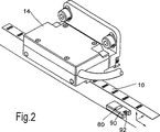
図2は、図1に示した装置の斜視図である。
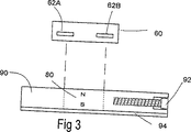
図3は、本発明により配置した参照マークを示す図である。
図4は、図3に示した参照マークの動作を示す信号のグラフである。
図5は、図2および図3の参照マークの変形例の立面図である。
図1において、スケール10は、一連の交互に光反射と無反射の線を一定間隔で配置している。線はx方向に伸びており、y方向に一定間隔で配置されている。読み取りヘッド14は、スケールに合わせて、それからz方向の間隔で搭載されており、スケール10に対してy方向に可動である。。読み取りヘッド14は、光源、および、回析格子のような1または2以上の光学要素を含んでいる。光学要素は、スケール10から反射した光とともに、読み取りヘッド14中に周期的な光パターンを発生する。スケール10と読み取りヘッド14の相対な動きは、対応する周期的な光パターンの動きを生じ、これにより、サイクリックに変化する光強度変調を生じる。読み取りヘッド中の複数の光検出器は、周期的な光パターンに対して相互に位相がシストされた関係に配置され、変調する光強度に対応する複数の電気的信号を発生する。これらの電気的信号は、合成されて、正弦波のように変化し、直角の関係を有する一対の信号Q1,Q2を発生する。読み取りヘッドに対する光学的構成は、たとえば、GB1,504,691、WO86/03833,WO87/07944から知ることができる。
直角関係の信号(quadrature signals)Q1,Q2は、スケール10上の参照位置に対する相対的な読み取りヘッド14の変位に対応する増分カウンタ(incremental couner)の基礎を形成する。さらに、読み取りヘッド14のスケール10に対する相対的な動きを、直角関係の信号Q1,Q2の1サイクルの部分以内に分解することができる。信号Q1,Q2は、一つの信号を他の信号に対して見ると、円形のリサージュ図形20を発生すると考えられる。直角関係の信号の1サイクルが円の一回転に対応している。サブサイクルの分解能は、この様に、円を等しい数の部分に分割することにより得ることができる。
直角関係の信号Q1,Q2は、補間回路30の入力である。補間回路30は、方形波整流(squarewave rectifying)および周波数逓倍(たとえば、5倍)を信号Q1,Q2に対して行い、直角関係にある、2つの一連の方形波出力パルスQUADA、QUADBを生成する。パルスQUADA,QUADBは、カウンタ40に送られる。カウンタは、それから増分合計(incremental total)を発生する。合計は、QUADAパルスがQUADBに対して90°前に到着した場合は増加し、QUADBパルスがQUADA対して90°前に到着した場合は減少する。カウンタの合計の変化は、信号QUADA,QUADBの立ち上がり、立ち下がりの各エッジで起こる。補間回路30から5倍の周波数逓倍により、信号Q1,Q2の1サイクルの1/20の分解能を可能にする。加えて、補間回路30は、内部的に、参照方形波パルスREFを直角関係の信号Q1,Q2の1サイクルに1つ発生する。パルスREFは、補間回路が読み取りヘッドからゼロ出力を受け取ったとき、カウンタ40に送出され、カウンタ40の出力をゼロとする。
図2から図4を参照して、ゼロ出力の状態の変化は、読み取りヘッド14中に配置された磁界検出器60および関連する処理電子機器(図示せず)により送出される。これは、検出器60が、スケール上に、たとえばスケールのトラックに隣接するスケールの基盤上に、配置されている永久磁石80の形の参照マークに対して、正確な位置となったときである。参照マークが強磁性の基盤上に搭載されている場合、磁界中の変動を減少するために、永久磁石80およびケース90は鋼鉄基盤94上に搭載される。
磁界検出器60は、2つの個々のホール素子検出器62A,Bを含み、2つのホール素子検出器の差分出力A−Bがゼロを通過するとき、ステップ出力を発生する。ステップの変化は、差分の遷移が一方の方向である場合は正であり、他の方向である場合は負である。直角関係の信号Q1,Q2(および、信号QUADA,QUADBおよびREF)のゼロ・パルスに対する相対的な位相を調整するため、永久磁石80により発生される磁束密度は、所定のz方向の乖離におけるx方向最高磁束密度の位置を変化させることにより、調整される。これは、磁石80を、強磁性調整要素をねじ92の形態で一方の端に格納した非強磁性ケース90の内側に搭載することで達成される。ねじはケース90に挿入したり引き出したりして、磁石80の近傍の空間の透磁率を、そして、磁石と合致している空間における磁束密度を変化させる。これは、次に、ホール素子検出器の差分ステップ出力が発生する、参照マークと読み取りヘッドとの相対的位置に影響を及ぼし、ゼロ・パルスが送出される時間/相対位相の調整を可能にする。
参照マークの変形例として、図5の立面図に示されているが、永久磁石180の隣接する領域における磁束密度は、2つの強磁性調整ボルト192の1つにより調整される。ボルトは、プラスティック・ケース190内部に搭載された、スケールと読み取りヘッドの相対的動きの方向Dにある角度の関係で伸びている。これは、固定しているボルト200のための空間を許容する。
他の実施例において、スケール上の参照マークは、非磁化された軟鉄強磁性要素の形態を有している。読み取りヘッドは、永久磁石(または、他の源、たとえば電磁石)および磁気検出器を含んでいる。スケール上の軟鉄要素は、比較的高い透磁率の磁気回路を効率的に完成する。結果的に、軟鉄要素と読み取りヘッドとが合ったとき、磁束を読み取りヘッド内の磁気検出器に「伝達する」。
実施例の変形例のどちらも、ゼロ・パルスの位相は、読み取りヘッドの所定の変位における磁束密度を変化させることで調整することができる。これは、強磁性調整要素(たとえば、永久磁石または軟鉄要素)を、読み取りヘッド内のホール素子検出器の領域で調整することによりできる。他の変形例として、他の磁気検出器(ホール素子検出器または差分検出器である必要はない)を使用することができる。
本発明は、反射型光学エンコーダ(reflective optical encoder)に関する例として説明されている。透過型光学エンコーダ(transmissive optical encoder)や磁気、容量性等のエンコーダにも使用できる。The present invention relates to a scale reading apparatus of the type comprising a scale defined by a series of lines arranged at regular intervals and a read head movable in the direction of the line spacing relative to the scale. In one type of such apparatus, the read head includes a light source that illuminates the scale and a number of optical elements that cooperate with the scale to generate a periodic optical pattern. The relative movement of the scale and the read head causes a corresponding periodic optical pattern movement, creating a cyclic light intensity modulation. The read head also includes a plurality of optical detection elements, to which a light intensity modulation is input, and a cyclically modulated electrical signal having a plurality of phase shifts corresponding to the light intensity modulation is received. Output. These signals are sent to a signal conditioning circuit, which synthesizes the signals and generates a pair of signals in a quadrature relationship (quadrature:
This type of device typically operates incrementally. The quadrature signal output from the signal conditioning circuit is the basis for generating the sum on the counter. This sum indicates the relative displacement between the scale and the read head. The sum on the counter increases or decreases depending on the number of cycles of orthogonal signals received and the order in which these signals arrive at the counter. However, it is also necessary to provide an absolute indication of the relative position of the scale and the read head. This is, for example, so that the error map associated with the scale can be initialized from the same repeatable position. This is typically provided by reference marks placed on the scale. When the reference detector in the read head is aligned with the reference mark, the read head issues a zero pulse with the reference mark. In order to obtain the best device stability against thermal drift, for example, it is desirable to deliver a zero pulse from the read head at the midpoint of a quadrature signal cycle. In order to ensure this, the relative phase of the quadrature cycle and the zero pulse needs to be adjustable.
The present invention relates to an optoelectronic (optical / electronic) scale reader comprising a scale defined by a series of spaced parallel lines and a read head movable relative to each other in the direction of the line spacing. A light source that illuminates the scale, one or more optical elements that cooperate with the scale to generate a periodic optical pattern and cyclically modulated light intensity, and one or more photodetectors; And a pair of signals that vary like a sine wave and that can define the relative magnitude and direction of motion and the associated electronic processing circuitry that is generated, said device further in the form of a ferromagnetic element A reference mark on the scale and a magnetic detector in the read head, the magnetic detector generating a reference pulse when a predetermined relationship with the ferromagnetic element is obtained; The magnetic flux intensity in the region of the magnetic detector is such that the position of another ferromagnetic element that is movably joined to the first ferromagnetic element when the read head is in a position adjacent to the reference mark, or , And can be varied by adjusting the proximity of the detector in the read head, wherein the further ferromagnetic element has a permeability substantially greater than the permeability of free space.
Preferably, the magnetic field is generated by a permanent magnet, which is arranged in the read head or near the ferromagnetic element. A magnetic field source that is independent of the reference mark and the read head may be employed.
Embodiments of the invention will now be described by way of example and with reference to the following drawings in which:
FIG. 1 is a diagram showing the configuration of a scale and a read head according to the present invention.
FIG. 2 is a perspective view of the apparatus shown in FIG.
FIG. 3 is a diagram showing reference marks arranged according to the present invention.
FIG. 4 is a signal graph showing the operation of the reference mark shown in FIG.
FIG. 5 is an elevation view of a variation of the reference mark of FIGS.
In FIG. 1, the
The quadrature signals Q 1 and Q 2 form the basis of an incremental counter that corresponds to the displacement of the
The orthogonally related signals Q 1 and Q 2 are inputs to the
With reference to FIGS. 2-4, the change in state of zero output is delivered by a
The
As a modification of the reference mark, shown in the elevation view of FIG. 5, the magnetic flux density in the adjacent region of the
In another embodiment, the reference mark on the scale has the form of a non-magnetized soft iron ferromagnetic element. The read head includes a permanent magnet (or other source, such as an electromagnet) and a magnetic detector. The soft iron element on the scale effectively completes a relatively high permeability magnetic circuit. As a result, when the soft iron element and the read head meet, the magnetic flux is “transmitted” to a magnetic detector in the read head.
In both of the embodiment variants, the phase of the zero pulse can be adjusted by changing the magnetic flux density at a given displacement of the read head. This can be done by tuning a ferromagnetic tuning element (eg a permanent magnet or soft iron element) in the area of the Hall element detector in the read head. As another variation, other magnetic detectors (not necessarily Hall element detectors or differential detectors) can be used.
The present invention has been described as an example relating to a reflective optical encoder. It can also be used for transmissive optical encoders and magnetic and capacitive encoders.
Claims (8)
強磁性要素を含む、前記スケール上の参照マークと、
前記読み取りヘッドおよび参照マークが特定の相対的位置のとき、参照パルスを発生する、前記読み取りヘッド中の磁気検出器と
強磁性の物質で作成された調整要素であって、読み取りヘッド中またはスケール上にあり、読み取りヘッドと参照マークとが合ったとき、前記磁気検出器の領域中の磁束を変化するように、そして、スケールと読み取りヘッドとの、参照パルスが発生する特定の相対的位置が変化するように、その位置は調整可能である調整要素と
を備えたことを特徴とするスケール読み取り装置。A scale defined by a series of spaced lines and a read head, wherein the scale and the read head are capable of relative displacement, thereby generating a cyclically changing signal; In the scale reading device used to create an increment representing the relative displacement of the scale and the read head from the reference mark,
A reference mark on the scale including a ferromagnetic element;
An adjustment element made of a magnetic detector and a ferromagnetic material in the read head that generates a reference pulse when the read head and the reference mark are in a specific relative position, in the read head or on the scale When the read head and the reference mark are aligned, the magnetic flux in the area of the magnetic detector is changed, and the specific relative position where the reference pulse is generated between the scale and the read head changes. A scale reading device comprising an adjustment element whose position is adjustable.
Applications Claiming Priority (3)
| Application Number | Priority Date | Filing Date | Title |
|---|---|---|---|
| GBGB9605278.2A GB9605278D0 (en) | 1996-03-13 | 1996-03-13 | Opto-electronic scale reading apparatus |
| GB9605278.2 | 1996-03-13 | ||
| PCT/GB1997/000594 WO1997034126A1 (en) | 1996-03-13 | 1997-03-05 | Scale reading apparatus |
Publications (2)
| Publication Number | Publication Date |
|---|---|
| JPH11506211A JPH11506211A (en) | 1999-06-02 |
| JP3676819B2 true JP3676819B2 (en) | 2005-07-27 |
Family
ID=10790314
Family Applications (1)
| Application Number | Title | Priority Date | Filing Date |
|---|---|---|---|
| JP53234597A Expired - Fee Related JP3676819B2 (en) | 1996-03-13 | 1997-03-05 | Scale reader |
Country Status (7)
| Country | Link |
|---|---|
| US (1) | US6051971A (en) |
| EP (1) | EP0826138B1 (en) |
| JP (1) | JP3676819B2 (en) |
| AT (1) | ATE200707T1 (en) |
| DE (1) | DE69704593T2 (en) |
| GB (1) | GB9605278D0 (en) |
| WO (1) | WO1997034126A1 (en) |
Families Citing this family (23)
| Publication number | Priority date | Publication date | Assignee | Title |
|---|---|---|---|---|
| DE19813375B4 (en) * | 1998-03-26 | 2007-07-19 | Dr. Johannes Heidenhain Gmbh | Position measuring device and method for mounting a reference element by means of a mounting aid |
| DE20011703U1 (en) * | 2000-07-07 | 2000-11-23 | Elgo Electric Gmbh | Length measuring device |
| WO2002010689A1 (en) * | 2000-08-02 | 2002-02-07 | Continental Teves Ag & Co. Ohg | Active magnetic field sensor, use thereof, method and device |
| DE10106479B4 (en) * | 2001-02-13 | 2004-02-19 | Asm Automation Sensorik Messtechnik Gmbh | Magnetic length measuring device |
| US20020133964A1 (en) * | 2001-02-13 | 2002-09-26 | Asm Automation Sensorik Messtechnik Gmbh | Magnetic length measuring device |
| DE10123539B4 (en) * | 2001-05-15 | 2008-07-17 | Asm Automation Sensorik Messtechnik Gmbh | Magnetic length measuring device |
| US20020190710A1 (en) * | 2001-02-13 | 2002-12-19 | Asm Automation Sensorik Messtechnik Gmbh | Magnetic length measuring device |
| US6556153B1 (en) | 2002-01-09 | 2003-04-29 | Anorad Corporation | System and method for improving encoder resolution |
| US6777926B2 (en) * | 2002-08-02 | 2004-08-17 | Honeywell International Inc. | Phase stability of non-sinusoidal signals utilizing two differential halls |
| DE10313676A1 (en) * | 2003-03-26 | 2004-10-07 | Imi Norgren-Herion Fluidtronic Gmbh & Co. Kg | Position measuring device for fluidic cylinder-piston arrangements |
| GB0316921D0 (en) * | 2003-07-19 | 2003-08-27 | Renishaw Plc | Reader for a scale marking |
| JP4587708B2 (en) * | 2004-05-20 | 2010-11-24 | コニカミノルタオプト株式会社 | Position detection device, camera shake correction mechanism, and imaging device |
| ES2360226T3 (en) * | 2005-10-13 | 2011-06-02 | Fagor, S.Coop. | REFERENCE UNIT FOR AN OPTOELECTRONIC MEASUREMENT DEVICE. |
| GB0522651D0 (en) * | 2005-11-07 | 2005-12-14 | Renishaw Plc | Scale and readhead system |
| ATE459856T1 (en) | 2006-09-05 | 2010-03-15 | Renishaw Plc | SURFACE MEASURING DEVICE |
| DE102007009994A1 (en) * | 2007-03-01 | 2008-09-04 | Robert Bosch Gmbh | Inductive sensor |
| DE102009051353A1 (en) * | 2009-10-30 | 2011-05-12 | Aktiebolaget Skf | Measuring arrangement for detecting a rotational movement |
| DE202010007285U1 (en) * | 2010-05-21 | 2011-09-23 | Balluff Gmbh | Gauge device for a position / displacement measuring system, position / displacement measuring system and application to which a position / displacement measuring system is mounted |
| LT3384246T (en) * | 2015-12-03 | 2020-07-10 | Renishaw Plc | Encoder apparatus |
| FR3070914B1 (en) * | 2017-09-14 | 2019-09-06 | Faurecia Sieges D'automobile | MECHANISM FOR ADJUSTING THE SEAT OF A MOTOR VEHICLE |
| EP3663723A1 (en) * | 2018-12-04 | 2020-06-10 | Renishaw PLC | Encoder apparatus |
| CN111486878A (en) * | 2020-05-08 | 2020-08-04 | 长春晟博光学技术开发有限公司 | Integrated magnetic grid ruler encoder with limiting function |
| US11846529B2 (en) | 2021-04-19 | 2023-12-19 | Joral Llc | Magnetic rack and pinion linear magnetic encoder and position sensing system |
Family Cites Families (18)
| Publication number | Priority date | Publication date | Assignee | Title |
|---|---|---|---|---|
| GB1504691A (en) * | 1974-03-15 | 1978-03-22 | Nat Res Dev | Measurement apparatus |
| SU670802A1 (en) * | 1974-07-24 | 1979-06-30 | Московское Ордена Ленина И Ордена Трудового Красного Знамени Высшее Техническое Училище Им. Н.Э.Баумана | Positioning displacement measuring system |
| FR2310549A1 (en) * | 1975-05-07 | 1976-12-03 | Sagem | IMPROVEMENTS TO OPTICAL DEVICES FOR DETERMINING THE POSITION OF A MOBILE ORGAN |
| DE2540412B2 (en) * | 1975-09-11 | 1979-08-02 | Dr. Johannes Heidenhain Gmbh, 8225 Traunreut | Incremental measuring system |
| US4143267A (en) * | 1977-12-23 | 1979-03-06 | Johnson Lonnie G | Digital distance measuring instrument |
| CH612500A5 (en) * | 1978-01-20 | 1979-07-31 | Hans Litscher | Length- and angle-measuring instrument having secondary stepped scales |
| DE3035012C2 (en) * | 1980-09-17 | 1982-08-12 | Fa. Carl Zeiss, 7920 Heidenheim | Device for angle measurement |
| DD159211A1 (en) * | 1981-05-29 | 1983-02-23 | Franz Kebschull | ARRANGEMENT FOR ASSESSMENT OF AN INDEX AGAINST A DIVISION |
| US4400890A (en) * | 1981-10-26 | 1983-08-30 | Sony Corporation | Length measuring device |
| DE3245357C2 (en) * | 1982-12-08 | 1985-02-14 | Dr. Johannes Heidenhain Gmbh, 8225 Traunreut | Incremental measuring device |
| DE3311204A1 (en) * | 1983-03-26 | 1984-10-04 | Dr. Johannes Heidenhain Gmbh, 8225 Traunreut | INCREMENTAL LENGTH OR ANGLE MEASURING DEVICE |
| DD219566A1 (en) * | 1983-08-05 | 1985-03-06 | Harry Trumpold | HIGH DEFLECTIVE OPTICAL LENGTH MEASURING PROCEDURE WITH CODED ABSOLUTE MEASURING TOOL FOR IMPLEMENTING THE PROCESS |
| SE8404266L (en) * | 1984-08-28 | 1985-09-02 | Johansson Ab C E | ASSUME THE ACCURACY OF A LENGTH SYSTEM BY CALIBRATING THIS AGAINST A CLOSER REFERENCE SYSTEM |
| US4829248A (en) * | 1984-09-20 | 1989-05-09 | Loubier Robert J | Hall effect sensing apparatus and method |
| GB8432574D0 (en) * | 1984-12-22 | 1985-02-06 | Renishaw Plc | Opto-electronic scale-reading apparatus |
| GB8615196D0 (en) * | 1986-06-21 | 1986-07-23 | Renishaw Plc | Opto-electronic scale reading apparatus |
| SE460928B (en) * | 1986-10-13 | 1989-12-04 | Johansson Ab C E | ABSOLUTELY MEASURING SCALE SYSTEM |
| US5500589A (en) * | 1995-01-18 | 1996-03-19 | Honeywell Inc. | Method for calibrating a sensor by moving a magnet while monitoring an output signal from a magnetically sensitive component |
-
1996
- 1996-03-13 GB GBGB9605278.2A patent/GB9605278D0/en active Pending
-
1997
- 1997-03-05 AT AT97905329T patent/ATE200707T1/en active
- 1997-03-05 JP JP53234597A patent/JP3676819B2/en not_active Expired - Fee Related
- 1997-03-05 WO PCT/GB1997/000594 patent/WO1997034126A1/en active IP Right Grant
- 1997-03-05 US US08/930,181 patent/US6051971A/en not_active Expired - Lifetime
- 1997-03-05 DE DE69704593T patent/DE69704593T2/en not_active Expired - Lifetime
- 1997-03-05 EP EP97905329A patent/EP0826138B1/en not_active Expired - Lifetime
Also Published As
| Publication number | Publication date |
|---|---|
| US6051971A (en) | 2000-04-18 |
| EP0826138B1 (en) | 2001-04-18 |
| DE69704593T2 (en) | 2001-08-09 |
| WO1997034126A1 (en) | 1997-09-18 |
| ATE200707T1 (en) | 2001-05-15 |
| EP0826138A1 (en) | 1998-03-04 |
| JPH11506211A (en) | 1999-06-02 |
| GB9605278D0 (en) | 1996-05-15 |
| DE69704593D1 (en) | 2001-05-23 |
Similar Documents
| Publication | Publication Date | Title |
|---|---|---|
| JP3676819B2 (en) | Scale reader | |
| KR100497467B1 (en) | Magnetic encoder with an index pulse | |
| US7571552B2 (en) | Scale reading apparatus | |
| US5412317A (en) | Position detector utilizing absolute and incremental position sensors in combination | |
| US6018881A (en) | Position measuring system | |
| CN110030924B (en) | Position measuring device | |
| JP2819507B2 (en) | Magnetic measuring system | |
| US6285023B1 (en) | Apparatus for generating origin signal of optical linear scale | |
| US6326908B1 (en) | Precision position encoder using coarse position indicator | |
| US3942002A (en) | Signal combining circuits | |
| Woolvet | Digital transducers | |
| US6356076B1 (en) | System for outputting a plurality of signals as a collective representation of incremental movements of an object | |
| EP0192812B1 (en) | Position sensing system | |
| US4864230A (en) | Processing quadrature signals | |
| JP2004264136A (en) | Position detector | |
| JP4400996B2 (en) | Origin signal generator | |
| JP2001041730A (en) | Linear scale | |
| JPH11271026A (en) | Dimension measuring apparatus using optical scale | |
| JP2003083772A (en) | Size measuring apparatus using optical scale | |
| KR20030060857A (en) | position finder method of digital and analog hybrid type | |
| JPS61102822A (en) | Encoder | |
| JPS6348416A (en) | Encoder device | |
| JPS5951305A (en) | Apparatus for measuring displacement | |
| JPH03238315A (en) | Electromagnetically coupled type position sensor | |
| JP2004347358A (en) | Displacement measuring apparatus |
Legal Events
| Date | Code | Title | Description |
|---|---|---|---|
| A521 | Request for written amendment filed |
Free format text: JAPANESE INTERMEDIATE CODE: A523 Effective date: 20040303 |
|
| A621 | Written request for application examination |
Free format text: JAPANESE INTERMEDIATE CODE: A621 Effective date: 20040303 |
|
| TRDD | Decision of grant or rejection written | ||
| A01 | Written decision to grant a patent or to grant a registration (utility model) |
Free format text: JAPANESE INTERMEDIATE CODE: A01 Effective date: 20050405 |
|
| A61 | First payment of annual fees (during grant procedure) |
Free format text: JAPANESE INTERMEDIATE CODE: A61 Effective date: 20050502 |
|
| R150 | Certificate of patent or registration of utility model |
Free format text: JAPANESE INTERMEDIATE CODE: R150 |
|
| FPAY | Renewal fee payment (event date is renewal date of database) |
Free format text: PAYMENT UNTIL: 20090513 Year of fee payment: 4 |
|
| FPAY | Renewal fee payment (event date is renewal date of database) |
Free format text: PAYMENT UNTIL: 20090513 Year of fee payment: 4 |
|
| FPAY | Renewal fee payment (event date is renewal date of database) |
Free format text: PAYMENT UNTIL: 20100513 Year of fee payment: 5 |
|
| FPAY | Renewal fee payment (event date is renewal date of database) |
Free format text: PAYMENT UNTIL: 20110513 Year of fee payment: 6 |
|
| FPAY | Renewal fee payment (event date is renewal date of database) |
Free format text: PAYMENT UNTIL: 20120513 Year of fee payment: 7 |
|
| FPAY | Renewal fee payment (event date is renewal date of database) |
Free format text: PAYMENT UNTIL: 20130513 Year of fee payment: 8 |
|
| R250 | Receipt of annual fees |
Free format text: JAPANESE INTERMEDIATE CODE: R250 |
|
| R250 | Receipt of annual fees |
Free format text: JAPANESE INTERMEDIATE CODE: R250 |
|
| R250 | Receipt of annual fees |
Free format text: JAPANESE INTERMEDIATE CODE: R250 |
|
| LAPS | Cancellation because of no payment of annual fees |