US4400890A - Length measuring device - Google Patents
Length measuring device Download PDFInfo
- Publication number
- US4400890A US4400890A US06/314,775 US31477581A US4400890A US 4400890 A US4400890 A US 4400890A US 31477581 A US31477581 A US 31477581A US 4400890 A US4400890 A US 4400890A
- Authority
- US
- United States
- Prior art keywords
- magnetic
- origin
- signal magnetic
- scale
- detecting head
- Prior art date
- Legal status (The legal status is an assumption and is not a legal conclusion. Google has not performed a legal analysis and makes no representation as to the accuracy of the status listed.)
- Expired - Lifetime
Links
Images

Classifications
-
- G—PHYSICS
- G01—MEASURING; TESTING
- G01B—MEASURING LENGTH, THICKNESS OR SIMILAR LINEAR DIMENSIONS; MEASURING ANGLES; MEASURING AREAS; MEASURING IRREGULARITIES OF SURFACES OR CONTOURS
- G01B7/00—Measuring arrangements characterised by the use of electric or magnetic techniques
- G01B7/02—Measuring arrangements characterised by the use of electric or magnetic techniques for measuring length, width or thickness
Definitions
- This invention relates to length measuring devices and more particularly, to length measuring devices in which standard graduations of a planar magnetic scale formed in a magnetic grating are read by a detecting head.
- Length measuring systems using a magnetic scale formed on a magnetic grating are generally based upon an incremental counting system, in which pulse signals for each unit displacement of a detecting head relative to a magnetic scale are counted to derive a measurement value.
- a length measuring system based upon such an incremental counting system is simple in construction and relatively inexpensive to manufacture. However, previously calculated positional information is entirely lost in such systems with a loss of power.
- iron and other particles are likely to accumulate on the surface of the magnetic scale. If these particles are caught between the magnetic scale and the detecting head when it moves, they can damage the detecting head and the magnetic scale.
- It is an object of the present invention is to provide a length measuring system which measures absolute distances from an origin or start point using a magnetic grating.
- a length measuring device has a magnetic scale body including at least one origin signal magnetic section and a measurement signal magnetic section forming a magnetic grating, the magnetic scale body having a uniform frictional surface formed over the entire effective length of the scale body, and a detecting head body including an origin detecting head for detecting an origin signal and a measurement detecting head for detecting a measurement signal and provided with a scraper in elastic contact with the frictional surface of the magnetic scale body, the detecting head body being moved relative to the magnetic scale body along the length of the latter.
- FIG. 1 is a schematic plan view of a length measuring device in accord with the present invention
- FIG. 2 is longitudinal sectional view of the length measuring device of FIG. 1;
- FIG. 3 is a schematic plan view of another embodiment of a length measuring device in accord with the present invention.
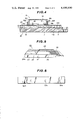
- FIG. 4 is a longitudinal sectional view of the length measuring device of FIG. 3;
- FIG. 5 is a partial, cutaway perspective view showing a modification of the magnetic scale body employed in the length measuring device according to the present invention.
- FIG. 6 is a schematic plan view showing a modification of the magnetic scale body according to the present invention.
- FIGS. 1 and 2 show an embodiment of the present invention applied to a magnetic scale device in which a magnetic grating is formed by a transverse magnetic recording.
- a magnetic scale body 4 includes a scale base 1 having, an origin signal magnetic member 2 disposed in a recess 1A formed at one end thereof, and a measurement signal magnetic member 3 covering a surface 1a of scale base 1, including a top 2a of origin signal magnetic member 2.
- Scale base 1 is made of a non-magnetic material.
- Origin signal magnetic member 2 can be a rare earth element magnet, a rubber magnet, a plastic magnet or the like and generates a magnetic field H O as an origin signal to indicate an origin or start point in a direction perpendicular to surface 1a.
- the Measurement signal magnetic member 3 can be a rolled magnet made of spinodal magnetic material such as Cu.Ni.Fe or Cu.Ni.Co and is magnetized to supply a magnetic grating which generates a surface field measurement signal from a transverse magnetic recording parallel to a frictional planar surface 4a.
- the rolled magnet forming measurement signal magnetic member 3 has a magnetic permeability ranging from 1 to 3. Covering surface 2a of origin signal magnetic member 2 does not significantly affect the signal field therefrom. Accordingly, the magnetic grating of measurement signal magnetic member 3 can be formed to cover origin signal magnetic member 2.
- a detecting head body 5, which is movable relative to magnetic scale body 4, includes a case 6 which houses an origin detecting head 7 and a measurement detecting head 8. Origin detecting head 7 and measurement detecting head 8 are spaced apart by a predetermined distance L 1 .
- Scrapers 9A and 9B are mounted on opposite side walls 6a and 6b of case 6.
- the Scrapers 9A and 9B are made of an elastic material such as polyrethane or nitrile rubber.
- the Scrapers 9A and 9B have respective sharp edges 9a and 9b which are in elastic contact with a frictional surface 4a of measurement signal magnetic member 3.
- scrapers 9A and 9B also move in frictional contact with frictional surface 4a of magnetic scale body 4 to remove iron particles deposited on frictional surface 4a.
- Origin detecting head 7 is a magnetic switch employing a ferromagnetic magnetic reluctance effect element or the like, and is secured in case 6 with a comparatively large clearance with respect to frictional surface 4a of magnetic scale body 4.
- Measurement detecting head 8 is a multigap magnetic head of a magnetic flux response type or a magnetic sensor also employing a ferromagnetic magnetic reluctance effect element. Measurement detecting head 8 is disposed in case 6 so that it moves in elastic contact with frictional surface 4a along with movements of detecting head body 5 over magnetic scale body 4.
- the illustrated embodiment is very suitable as a high resolution length measurement device, in which the magnetic grating has a short wavelength of 2 mm or less and is formed by a lateral magnetic field recording in measurement signal magnetic member 3 of magnetic scale body 4.
- Magnetic field H O from origin signal magnetic member 2 can be detected as a signal indicative of an origin or start point by origin detecting head 7.
- Signal field H S from measurement signal magnetic member 3, i.e., the measurement position information detected by the measurement detecting head 3 can be used as a signal indicative of an absolute position with relation to a start or origin point indicated by origin signal magnetic member 2.
- frictional surface 4a of magnetic scale body 4 is always cleaned by scrapers 9A and 9B, so that the illustrated embodiment of a length measurement device can withstand heavy use even in an environment where iron particles are scattered.
- FIGS. 3 and 4 show another embodiment of the present invention in which the magnetic grating is formed by longitudinal magnetic recording.
- a magnetic scale body 14 includes a scale base 11, an origin signal magnetic member 12 and a measurement signal magnetic member 13 formed thereon, and a protective layer 20 made of a non-magnetic material formed over the entire top surface of magnetic members 12 and 13.
- an origin track TR O in which origin signal magnetic member 12 is disposed
- a measurement track TR S in which measurement signal magnetic member 13 is disposed
- a magnetic head body 15 includes an origin detecting head 17 and a measurement detecting head 18 for tracing tracks TR O and TR S , respectively. Heads 17 and 18 are spaced apart a predetermined distance L 2 within body 15.
- Origin signal magnetic member 12 and measurement signal magnetic member 13 can be made of rubber magnet or barium ferrite which is readily available.
- Scale base 11 can be made of a magnetic material to reinforce signal field H S from measurement signal magnetic member 13. Further, in a portion of origin track TR O track away from origin signal magnetic member 12 a spacer 10 having substantially the same thickness t as measurement signal magnetic member 13 is interposed between scale base 11 and protective layer 20. In the illustrated embodiment, scale base 11 has a recess 11A to accommodate origin signal magnetic member 12.
- Spacer 10 comprising a magnetic plate, is used with measurement signal magnetic member 13 accurately to match thickness t of magnetic member 13 and spacer 10 so that the upper surface of protective layer 20 is smooth and level for detecting head body 15 to move thereover.
- Detecting head body 15 with opposite side walls 16a and 16b of head 16 has scrapers 19A and 19B attached thereto with corresponding sharp edges 19a and 19b of width T extending across tracks TR O and TR S .
- a magnetic grating as, for example, a comparatively large wavelength of 1 mm or more is formed by a longitudinal magnetic recording in measurement signal magnetic member 13. Accordingly, a length measuring device having a comparatively low resolution is provided. With a comparatively large wavelength for the magnetic grating, a large clearance between measurement signal magnetic member 13 and measurement detecting head 18 may be employed.
- the thickness of protective layer 20 functioning as a non-magnetic sheet on the surface of magnetic scale body 14 can also be sufficiently accommodated with a comparatively large clearance.
- a frictional surface 14a of magnetic scale body 14 can be a smoothly finished planar surface so that scrapers 19A and 19B can effectively clean surface 14a.
- an absolute length measurement output on the basis of the information of the point of origin can be derived.
- FIG. 5 shows a magnetic scale device utilizing a magnetic grating formed by the aforementioned longitudinal magnetic recording.
- the illustrated distance measuring device includes a scale base 21, a magnetic plate 25 made of barium ferrite, and a protective layer 30 made of a non-magnetic sheet of material.
- the magnetic grating formed by the longitudinal recording is selectively provided in a region of magnetic plate 25 corresponding to measurement track TR S , thus forming measurement signal magnetic member 23.
- Plate 25 on scale base 21 is formed in a region corresponding to origin track TR O and has a recess 26 to receive origin signal magnetic member 22.
- a protective layer 30 covers the entire surface of magnetic plate 25 and origin signal magnetic member 30 and provides a smooth planar frictional surface 24a for magnetic scale body 24.
- origin signal magnetic member 32a,32b . . . 32n in a magnetic scale body 32, as illustrated in the embodiment of FIG. 6.
- Multiple origin signal magnetic members 32a, 32b, . . . 32n provide information of respective predetermined positions to derive a length measurement output based upon the information from individual origin points 32a, 32b, . . . 32n.
Abstract
Description
Claims (7)
Priority Applications (1)
| Application Number | Priority Date | Filing Date | Title |
|---|---|---|---|
| US06/314,775 US4400890A (en) | 1981-10-26 | 1981-10-26 | Length measuring device |
Applications Claiming Priority (1)
| Application Number | Priority Date | Filing Date | Title |
|---|---|---|---|
| US06/314,775 US4400890A (en) | 1981-10-26 | 1981-10-26 | Length measuring device |
Publications (1)
| Publication Number | Publication Date |
|---|---|
| US4400890A true US4400890A (en) | 1983-08-30 |
Family
ID=23221390
Family Applications (1)
| Application Number | Title | Priority Date | Filing Date |
|---|---|---|---|
| US06/314,775 Expired - Lifetime US4400890A (en) | 1981-10-26 | 1981-10-26 | Length measuring device |
Country Status (1)
| Country | Link |
|---|---|
| US (1) | US4400890A (en) |
Cited By (20)
| Publication number | Priority date | Publication date | Assignee | Title |
|---|---|---|---|---|
| EP0085787A2 (en) * | 1982-02-05 | 1983-08-17 | Dr. Johannes Heidenhain GmbH | Measuring device |
| US4462159A (en) * | 1982-12-11 | 1984-07-31 | Dr. Johannes Heidenhain Gmbh | Reference mark selection system for measuring apparatus |
| US4491928A (en) * | 1980-10-18 | 1985-01-01 | Dr. Johannes Heidenhain Gmbh | Reference mark designating system for incremental position measuring instruments |
| US4490914A (en) * | 1982-01-15 | 1985-01-01 | Dr. Johannes Heidenhain Gmbh | Error correction system for position measuring instruments |
| US4519140A (en) * | 1981-11-07 | 1985-05-28 | Dr. Johannes Heidenhain Gmbh | System for identifying reference marks in a path measuring device |
| EP0188189A1 (en) * | 1985-01-11 | 1986-07-23 | RSF-Elektronik Gesellschaft m.b.H. | Encapsulated length-measuring device |
| US4628609A (en) * | 1984-07-06 | 1986-12-16 | Rsf-Elektronik Gesellschaft M.B.H. | Incremental measuring and machine control system |
| EP0209513A1 (en) * | 1985-07-10 | 1987-01-21 | RSF-Elektronik Gesellschaft m.b.H. | Measuring system for a machine tool |
| AT394070B (en) * | 1990-02-13 | 1992-01-27 | Bach Ges M B H Geb | Grid ceiling |
| US5165277A (en) * | 1990-08-29 | 1992-11-24 | Measurex Corporation | System and process for determining properties of a moving sheet of material |
| US5488782A (en) * | 1993-05-13 | 1996-02-06 | Sony Magnescale Inc. | Scale plate arrangement |
| FR2762907A1 (en) * | 1997-05-02 | 1998-11-06 | Roulements Soc Nouvelle | DEVICE FOR MEASURING THE ROTATION OF A ROTATING ELEMENT |
| US5992574A (en) * | 1996-12-20 | 1999-11-30 | Otis Elevator Company | Method and apparatus to inspect hoisting ropes |
| US6051971A (en) * | 1996-03-13 | 2000-04-18 | Renishaw Plc | Scale reading apparatus with a magnetic sensor unit for adjusting relative phase of the quadrature pulses |
| US20150164607A1 (en) * | 2012-06-20 | 2015-06-18 | Koninklijke Philips N.V. | Multicamera device tracking |
| US20150219475A1 (en) * | 2014-02-04 | 2015-08-06 | Mitutoyo Corporation | Linear encoder |
| AT14635U1 (en) * | 2014-09-11 | 2016-02-15 | Teufelberger Holding Ag | fiber rope |
| DE19913659B4 (en) * | 1998-03-31 | 2016-12-08 | Dmg Mori Seiki Co., Ltd. | Position detection device |
| DE102016205162A1 (en) * | 2016-03-30 | 2017-10-05 | Zf Friedrichshafen Ag | Protective device, magnetic sensor device and gearbox device |
| CN117022373A (en) * | 2023-10-08 | 2023-11-10 | 武汉江腾铁路工程有限责任公司 | Measuring device for railway basic data |
Citations (6)
| Publication number | Priority date | Publication date | Assignee | Title |
|---|---|---|---|---|
| FR1116613A (en) * | 1953-12-31 | 1956-05-09 | British Thomson Houston Co Ltd | Positioning device |
| US2918666A (en) * | 1956-07-30 | 1959-12-22 | Hughes Aircraft Co | Condition responsive electrical system |
| FR2030713A5 (en) * | 1969-11-27 | 1970-11-13 | Cical Bernard | |
| GB1302762A (en) * | 1970-02-06 | 1973-01-10 | ||
| US4028603A (en) * | 1972-07-31 | 1977-06-07 | Gabriel Selam | Device for detecting and positioning a mobile object capable of moving in at least one given path |
| US4229647A (en) * | 1977-07-21 | 1980-10-21 | Dr. Johannes Heidenhain Gmbh | Counter system for incremental measuring instrument |
-
1981
- 1981-10-26 US US06/314,775 patent/US4400890A/en not_active Expired - Lifetime
Patent Citations (6)
| Publication number | Priority date | Publication date | Assignee | Title |
|---|---|---|---|---|
| FR1116613A (en) * | 1953-12-31 | 1956-05-09 | British Thomson Houston Co Ltd | Positioning device |
| US2918666A (en) * | 1956-07-30 | 1959-12-22 | Hughes Aircraft Co | Condition responsive electrical system |
| FR2030713A5 (en) * | 1969-11-27 | 1970-11-13 | Cical Bernard | |
| GB1302762A (en) * | 1970-02-06 | 1973-01-10 | ||
| US4028603A (en) * | 1972-07-31 | 1977-06-07 | Gabriel Selam | Device for detecting and positioning a mobile object capable of moving in at least one given path |
| US4229647A (en) * | 1977-07-21 | 1980-10-21 | Dr. Johannes Heidenhain Gmbh | Counter system for incremental measuring instrument |
Cited By (27)
| Publication number | Priority date | Publication date | Assignee | Title |
|---|---|---|---|---|
| US4491928A (en) * | 1980-10-18 | 1985-01-01 | Dr. Johannes Heidenhain Gmbh | Reference mark designating system for incremental position measuring instruments |
| US4519140A (en) * | 1981-11-07 | 1985-05-28 | Dr. Johannes Heidenhain Gmbh | System for identifying reference marks in a path measuring device |
| US4490914A (en) * | 1982-01-15 | 1985-01-01 | Dr. Johannes Heidenhain Gmbh | Error correction system for position measuring instruments |
| EP0085787A2 (en) * | 1982-02-05 | 1983-08-17 | Dr. Johannes Heidenhain GmbH | Measuring device |
| US4459750A (en) * | 1982-02-05 | 1984-07-17 | Dr. Johannes Heidenhain Gmbh | Reference mark selection arrangement for measuring instrument |
| EP0085787A3 (en) * | 1982-02-05 | 1986-02-05 | Dr. Johannes Heidenhain Gmbh | Measuring device |
| US4462159A (en) * | 1982-12-11 | 1984-07-31 | Dr. Johannes Heidenhain Gmbh | Reference mark selection system for measuring apparatus |
| US4628609A (en) * | 1984-07-06 | 1986-12-16 | Rsf-Elektronik Gesellschaft M.B.H. | Incremental measuring and machine control system |
| EP0188189A1 (en) * | 1985-01-11 | 1986-07-23 | RSF-Elektronik Gesellschaft m.b.H. | Encapsulated length-measuring device |
| US4631403A (en) * | 1985-01-11 | 1986-12-23 | Rsf Elektronik Gesellschaft M.B.H. | Length measuring instrument comprising a scale member and a signal-generating scanning unit which is movable along the scale member |
| EP0209513A1 (en) * | 1985-07-10 | 1987-01-21 | RSF-Elektronik Gesellschaft m.b.H. | Measuring system for a machine tool |
| AT394070B (en) * | 1990-02-13 | 1992-01-27 | Bach Ges M B H Geb | Grid ceiling |
| US5165277A (en) * | 1990-08-29 | 1992-11-24 | Measurex Corporation | System and process for determining properties of a moving sheet of material |
| US5488782A (en) * | 1993-05-13 | 1996-02-06 | Sony Magnescale Inc. | Scale plate arrangement |
| US6051971A (en) * | 1996-03-13 | 2000-04-18 | Renishaw Plc | Scale reading apparatus with a magnetic sensor unit for adjusting relative phase of the quadrature pulses |
| US5992574A (en) * | 1996-12-20 | 1999-11-30 | Otis Elevator Company | Method and apparatus to inspect hoisting ropes |
| FR2762907A1 (en) * | 1997-05-02 | 1998-11-06 | Roulements Soc Nouvelle | DEVICE FOR MEASURING THE ROTATION OF A ROTATING ELEMENT |
| WO1998050793A1 (en) * | 1997-05-02 | 1998-11-12 | Snr Roulements | Device for measuring the rotation of a rotating element |
| US6232772B1 (en) * | 1997-05-02 | 2001-05-15 | The Torrington Company | Device for measuring the rotation of a rotating element |
| DE19913659B4 (en) * | 1998-03-31 | 2016-12-08 | Dmg Mori Seiki Co., Ltd. | Position detection device |
| US20150164607A1 (en) * | 2012-06-20 | 2015-06-18 | Koninklijke Philips N.V. | Multicamera device tracking |
| US9506778B2 (en) * | 2014-02-04 | 2016-11-29 | Mitutoyo Corporation | Linear encoder |
| US20150219475A1 (en) * | 2014-02-04 | 2015-08-06 | Mitutoyo Corporation | Linear encoder |
| AT14635U1 (en) * | 2014-09-11 | 2016-02-15 | Teufelberger Holding Ag | fiber rope |
| DE102016205162A1 (en) * | 2016-03-30 | 2017-10-05 | Zf Friedrichshafen Ag | Protective device, magnetic sensor device and gearbox device |
| CN117022373A (en) * | 2023-10-08 | 2023-11-10 | 武汉江腾铁路工程有限责任公司 | Measuring device for railway basic data |
| CN117022373B (en) * | 2023-10-08 | 2024-01-12 | 武汉江腾铁路工程有限责任公司 | Measuring device for railway basic data |
Similar Documents
| Publication | Publication Date | Title |
|---|---|---|
| US4400890A (en) | Length measuring device | |
| US4820961A (en) | Linear motion screened inductance sensors | |
| KR100194164B1 (en) | Hydraulic cylinder | |
| DE19719905A1 (en) | Electronic caliper with an inductive low-power position transducer | |
| DE69219750T2 (en) | Magnetoresistive sensor for weak magnetic fields | |
| US20070074416A1 (en) | Absolute position measurement system and method of producing material measure for the same | |
| DE59812241D1 (en) | Sensor device for detecting the direction of an external magnetic field by means of a magnetoresistive sensor element | |
| JPS59114403A (en) | Measuring device | |
| EP0077423B1 (en) | Length measuring devices | |
| DE3483688D1 (en) | PHOTOMAGNETIC RECORDING AND PLAYING DEVICE WITH AN ARRANGEMENT FOR DETECTING THE MAGNETIZING DIRECTION OF A MAGNETIC RECORDING MEDIA. | |
| US20070070870A1 (en) | Servo pattern having reduced noise due to speed variations in linear data storage media | |
| CA1167545A (en) | Length measuring device | |
| JPH05264326A (en) | Linear position sensor | |
| US2963690A (en) | Magnetic transducer | |
| JPH0236089Y2 (en) | ||
| US5628120A (en) | Method for the measurement of lengths and angles and an equipment therefor | |
| CA1112330A (en) | Digital displacement transducer and method for measurement | |
| JPH057523Y2 (en) | ||
| ATE41514T1 (en) | MEASUREMENT ARRANGEMENT. | |
| JPS6222403B2 (en) | ||
| JPS57154014A (en) | Magnetic rotary encoder | |
| DE59510825D1 (en) | Position detection with two magnetic field sensors arranged side by side | |
| JP4223718B2 (en) | Position detection device | |
| JPH0261503A (en) | Magnetic scale device | |
| JPS5936144Y2 (en) | linear pulse motor |
Legal Events
| Date | Code | Title | Description |
|---|---|---|---|
| AS | Assignment |
Owner name: SONY CORPORATION, 7-35 KITASHNAGAWA-6 SHINAGAWA-KU Free format text: ASSIGNMENT OF ASSIGNORS INTEREST.;ASSIGNORS:OHKUBO, HIROYUKI;MARU, HIROSHI;KATO, YOSHITO;AND OTHERS;REEL/FRAME:003942/0757 Effective date: 19811020 |
|
| STCF | Information on status: patent grant |
Free format text: PATENTED CASE |
|
| AS | Assignment |
Owner name: SONY AND TOYOTA JIDOSHA KABUSHIKI KAISHA Free format text: ASSIGNMENT OF ASSIGNORS INTEREST.;ASSIGNOR:SONY CORPORATION;REEL/FRAME:004222/0851 |
|
| FEPP | Fee payment procedure |
Free format text: MAINTENANCE FEE REMINDER MAILED (ORIGINAL EVENT CODE: REM.); ENTITY STATUS OF PATENT OWNER: LARGE ENTITY |
|
| FEPP | Fee payment procedure |
Free format text: SURCHARGE FOR LATE PAYMENT, PL 96-517 (ORIGINAL EVENT CODE: M176); ENTITY STATUS OF PATENT OWNER: LARGE ENTITY |
|
| MAFP | Maintenance fee payment |
Free format text: PAYMENT OF MAINTENANCE FEE, 4TH YEAR, PL 96-517 (ORIGINAL EVENT CODE: M170); ENTITY STATUS OF PATENT OWNER: LARGE ENTITY Year of fee payment: 4 |
|
| FEPP | Fee payment procedure |
Free format text: PAYOR NUMBER ASSIGNED (ORIGINAL EVENT CODE: ASPN); ENTITY STATUS OF PATENT OWNER: LARGE ENTITY |
|
| MAFP | Maintenance fee payment |
Free format text: PAYMENT OF MAINTENANCE FEE, 8TH YEAR, PL 96-517 (ORIGINAL EVENT CODE: M171); ENTITY STATUS OF PATENT OWNER: LARGE ENTITY Year of fee payment: 8 |
|
| MAFP | Maintenance fee payment |
Free format text: PAYMENT OF MAINTENANCE FEE, 12TH YEAR, LARGE ENTITY (ORIGINAL EVENT CODE: M185); ENTITY STATUS OF PATENT OWNER: LARGE ENTITY Year of fee payment: 12 |