JP3674635B2 - Vacuum suction device for disk-shaped recording media - Google Patents
Vacuum suction device for disk-shaped recording media Download PDFInfo
- Publication number
- JP3674635B2 JP3674635B2 JP03184294A JP3184294A JP3674635B2 JP 3674635 B2 JP3674635 B2 JP 3674635B2 JP 03184294 A JP03184294 A JP 03184294A JP 3184294 A JP3184294 A JP 3184294A JP 3674635 B2 JP3674635 B2 JP 3674635B2
- Authority
- JP
- Japan
- Prior art keywords
- recording medium
- shaped recording
- disk
- suction
- guide
- Prior art date
- Legal status (The legal status is an assumption and is not a legal conclusion. Google has not performed a legal analysis and makes no representation as to the accuracy of the status listed.)
- Expired - Fee Related
Links
Images
Landscapes
- Manufacturing Of Magnetic Record Carriers (AREA)
- Manufacturing Optical Record Carriers (AREA)
- Manipulator (AREA)
Description
【0001】
【産業上の利用分野】
本発明は、小径な光ディスクや磁気ディスク等の円板状記録媒体を吸着する円板状記録媒体の真空吸着装置に関する。
【0002】
【従来の技術】
従来において、光ディスクや磁気ディスクを移動したり、また、成膜を施す等の各種の工程では、光ディスクや磁気ディスクを吸着する真空吸着式ハンドリング装置が用いられている。
この種のハンドリング装置では、光ディスクや磁気ディスクを吸着するバキュームパッドを備え、このバキュームパッドにより光ディスクや磁気ディスクが吸着され移送される。
また、従来のハンドリング装置においては、バキュームパッドが光ディスクや磁気ディスクに設けられる成膜エリヤ(記録エリヤ)の内側の中央部分を吸着できるように形成されており、光ディスクや磁気ディスクの成膜エリヤ(記録エリヤ)の内側の中央部分をバキュームパッドにより吸着して各種の作業を行なうことにより、バキュームパッドによる光ディスクや磁気ディスクの成膜エリヤ(記録エリヤ)内の傷や汚れ等が付くのを防止している。
これは、光ディスクや磁気ディスクに限らず、傷や汚れ等に弱い各種の円板状記録媒体についても同様に行なわれている。
【0003】
【発明が解決しようとする課題】
ところが、近年において、光ディスクや磁気ディスクが小径化しており、このような小径化に伴い、接触可能なエリヤが小さくなって吸着面積が小さくなってきた。
このため、従来のバキュームパッドのように、光ディスクや磁気ディスク等の円板状記録媒体の中央部分のみを吸着する方法では、円板状記録媒体に対する吸着力が低下してしまい、円板状記録媒体に対するハンドリングの信頼性が低下するというおそれがあった。
そこで、本発明では、光ディスクや磁気ディスク等の円板状記録媒体が小径化して中央部分の吸着面積が小さい場合でも、確実に吸着でき、更に吸着精度を高めることができる円板状記録媒体の真空吸着装置を提供することを目的としている。
【0005】
【課題を解決するための手段】
前記目的を達成するため、本発明は、移動可能なアームと、このアームに設けられた吸着部とを備え、円板状記録媒体を前記吸着部により吸着して移送する円板状記録媒体の真空吸着装置において、前記吸着部は、円板状記録媒体の記録エリアの内側部分に接触する内側接触部と、円板状記録媒体の記録エリアの外側部分に接触する外側接触部と、前記内側接触部と外側接触部の間に形成され、各内側接触部と外側接触部がそれぞれ円板状記録媒体の記録エリアの内側部分と外側部分に接触した状態で、前記内側接触部と外側接触部と円板状記録媒体の記録エリア部分と協働して閉塞空間を形成する吸引用凹部と、前記吸引用凹部に連通する真空吸引路とを備えたことを特徴とする。
また、本発明は、前記吸着部の外側に、先端に至り径方向外方に傾斜するテーパ面を有し円板状記録媒体の周縁に接触可能な案内部が設けられていることを特徴とする。
【0006】
また、本発明は、移動可能なアームと、このアームに設けられた吸着部とを備え、円板状記録媒体を前記吸着部により吸着して移送する円板状記録媒体の真空吸着装置において、前記吸着部は、円板状記録媒体の記録エリアの内側部分で円板状記録媒体の径方向に間隔を置いた箇所に接触可能に環状に形成された第1および第2内側接触部と、前記第1、第2内側接触部の間に形成され、各第1、第2内側接触部がそれぞれ円板状記録媒体の記録エリアの内側部分に接触した状態で、各第1、第2内側接触部と円板状記録媒体の記録エリアの内側部分と協働して閉塞空間を形成する吸引用凹部と、前記吸引用凹部に連通する真空吸引路と、前記吸着部の外側に設けられ、先端に至り径方向外方に傾斜するテーパ面を有し円板状記録媒体の周縁に接触可能な案内部とを備えたことを特徴とする。
【0007】
また、本発明は、前記アームと吸着部との間には、アームに対して吸着部を、円板状記録媒体の中心軸方向に沿って移動可能に支持するフローティング機構が介設されていることを特徴とする。
また、本発明は、前記フローティング機構が、前記アームに貫通固着された筒状のガイドブッシュと、前記ガイドブッシュに挿通されて基端部が前記ガイドブッシュに係止され先端部に前記吸着部が取付けられるガイドシャフトと、前記アームと吸着部との間に介装された付勢部材とからなることを特徴とする。
また、本発明は、前記フローティング構造が、前記吸着部に貫通固着された筒状のガイドブッシュと、前記ガイドブッシュに挿通されて先端部が前記ガイドブッシュに係止され基端部が前記アームに固着されたガイドシャフトと、前記アームと吸着部との間に介装された付勢部材とからなることを特徴とする。
【0008】
また、本発明は、前記案内部が、先端に向けて先細りに形成されて前記円板状記録媒体の周縁に接触可能なテーパ面を有し前記吸着部に取付けられた複数の案内ピンにより構成されていることを特徴とする。
また、本発明は、前記案内部が、前記円板状記録媒体の周縁に接触可能なテーパ面を有し前記吸着部に取付けられた円筒状の受け部材で構成されていることを特徴とする。
また、本発明は、前記案内部が、前記円板状記録媒体の周縁に接触可能な円錐面を有し前記吸着部に取付けられた円錐状の受け部材で構成されていることを特徴とする。
【0009】
【作用】
円板状記録媒体の中央部および周縁部に吸着部の接触部が接触して吸着されるので、従来のような中央部分のみを吸着する場合に比べて吸引面積が大きくなり、円板状記録媒体が小径化しても確実に吸着することができる。
また、吸着部をアームに設け、吸着部に案内部を設けると、円板状記録媒体を案内部により位置決めし、円板状記録媒体の吸着位置精度を高めることができ、これにより、円板状記録媒体の吸着保持を確実に行なうことができる。
更に、吸着部をアームに設け、吸着部とアームとの間にフローティング機構を設けると、吸着部に対して傾きや高さ位置誤差を有した状態から円板状記録媒体を吸着する場合、円板状記録媒体の傾きや高さ位置誤差を吸着時に吸収することができ、精度の高い吸着が可能となる。
【0010】
【実施例】
以下に、本発明の第1実施例を図面に基づき説明する。
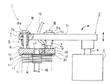
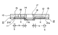
図1は本実施例の円板状記録媒体の真空吸着装置の要部断面側面図、図2はチャッキングプレートの断面側面図であり、本実施例では、小径化された光ディスクや磁気ディスク等の円板状記録媒体(以下、小径基板という)を吸着する場合について説明する。
本実施例の真空吸着装置1は、図1に示すように、移載装置2と、この移載装置2に取付けられた円板状のチャッキングプレート(吸着部)10とにより構成されている。
上記移載装置2は駆動部3と、軸部4と、アーム(ベースプレート)5により構成され、軸部4にアーム5が取付けられ、前記チャッキングプレート10はアーム5の先端部分にフローティング機構6を介して取付けられ、小径基板11はこのチャッキングプレート10に吸着される。
上記アーム5は、駆動部3の駆動により、軸部4の軸方向に移動したり、その基端部を中心に揺動したり、また、軸部4を中心に旋回移動できるようになっている。
【0011】
上記フローティング機構6は、複数のガイドブッシュ7、ガイドシャフト8、およびコイルスプリング9により構成され、複数のガイドブッシュ7およびガイドシャフト8はチャッキングプレート10の周方向の等間隔をおいた2〜3箇所に配設され、これらガイドブッシュ7およびガイドシャフト8は、吸着すべき小径基板11の中心軸と平行する方向に延在している。
上記各々のガイドブッシュ7は円筒状に形成され、その基端部には鍔部7aを備え、鍔部7aをアーム5に当接してアーム5を貫通して固着されており、各々のアーム5内にガイドシャフト8が挿通されている。
各々のガイドシャフト8は、その基端部に上記ガイドブッシュ7の鍔部7aに係止される鍔部8aを有し、先端部がチャッキングプレート10の背面部にそれぞれ取付けられており、アーム5とチャッキングプレート10との間でガイドブッシュ7、ガイドシャフト8の周囲にはコイルスプリング9が巻装され、チャッキングプレート10をアーム5から離す方向に付勢している。
したがって、アーム5およびフローティング機構6を介してチャッキングプレート10が小径基板11の中心軸方向に移動可能に支持され、これにより、小径基板11を吸着する際にチャッキングプレート10自体が自由度を有し、チャッキングプレート10による小径基板11の吸着がし易くなる。
【0012】
上記チャッキングプレート10は、吸着すべき小径基板11よりも僅かに大きな外径の円盤状に形成され、その表面には所定幅の吸引用凹部12が円周方向に亘って連続状に設けられている。
すなわち、一般に、光(磁気)ディスク等の小径基板11には、図2に示すように、円板状の中央部や周縁部分を除いて、記録・読取りのために記録読取りエリヤNがフォーマットされて接触禁止エリヤとなっており、この記録読取りエリヤNにはオングストローム単位の膜が形成されている。
本実施例では、チャッキングプレート10による吸着時にチャッキングプレート10の表面が記録読取りエリヤNに接触しないように、小径基板11の記録読取りエリヤNに対応した環状の形状で吸引用凹部12が設けられている。尚、図2中、Sは接触可能エリヤを示す。
【0013】
チャッキングプレート10の中央部分には、記録読取りエリヤNを除く小径基板11の中央部に接触する環状の接触面(内側接触部)14が設けられ、チャッキングプレート10の周縁部分には、記録読取りエリヤNを除く小径基板11の周縁部に接触する環状の接触面(外側接触部)15が設けられている。
そして、この環状の接触面14、15を記録読取りエリヤNを除く小径基板11の中央部および周縁部に接触させた状態で、接触面14、15と、吸引用凹部12と、小径基板11の記録読取りエリヤNとにより閉塞空間Kが形成されるように構成されている。
また、前記チャッキングプレート10の中央部には、小径基板11を段積みしてストックするポール式マガジンのポール16が挿通する挿通穴17が設けられている。
更に、上記吸引用凹部12は、チャッキングプレート10内に設けられた連通孔18およびバキュームチューブ19(真空吸引路)を通じて図示しない吸引装置の吸引ポートに接続され、チャッキングプレート10の周縁部分の接触面15の外周には複数の案内ピン(案内部)21が取付けられている。
これらの案内ピン21は、チャッキングプレート10の周方向の3箇所以上に等間隔に設けられ、先端に向けて先細りとなるように周面がテーパ面21aに形成されており、これらに案内ピン21によりマガジンラックから位置ずれすることなく小径基板11を吸着できる構造となっている。
【0014】
次に、上記真空吸着装置1により小径基板11を吸着して取出す場合について説明する。
ポール式マガジンのポール16には、小径基板11を同一方向に向けて小径基板11の中央部の穴11aを通すことにより、複数の小径基板11が段積みされてストックされている。
このようなポール式マガジンにストックされた小径基板11は、ポール16の傾きや、ポール径と小径基板11の穴径とのクリアランス等により、平面上の位置誤差を有している。
また、段積みされていることにより、集積高さも小径基板11の厚み誤差の累計からバラツキを有する。
更に、段積み状態で振動を伴うコンベアや台車等での搬送により、幾分かの傾きが発生してしまうのが実状である。
【0015】
このような状態の小径基板11を吸着してポール式マガジンから取出す場合には、移載装置2の駆動部3によりアーム5を旋回移動や揺動移動させた後、アーム5を軸部4の軸方向へ移動させてチャッキングプレート10をポール式マガジンの小径基板11に接近させると、先ず、各案内ピン21のテーパ面21aが取出そうとする小径基板11の周縁に接触し、これにより小径基板11は寄せられ、小径基板11の中心軸とチャッキングプレート10の中心軸が合わされる。
更に、チャッキングプレート10を下降させて接近させると、傾きを有する小径基板11の周縁部のより近接した箇所からチャッキングプレート10の周縁の接触面15に接触し、傾いた小径基板11を水平に矯正しつつ接近し、チャッキングプレート10が下降端に至る時点で小径基板11の中央部や周縁部の接触可能エリヤSがチャッキングプレート10の中央および周縁の接触面14、15に接触し、閉塞空間Kが形成される。
そして、この時点で真空ポンプにより真空吸引することにより、傾きが吸収矯正された状態で小径基板11がチャッキングプレート10に吸着され、アーム5の駆動により小径基板11は所定箇所に移送され、例えば、記録読取りエリヤに膜を形成する成膜工程作業が行なわれ、終了後に別のマガジンまで移送されストックされる。
【0016】
したがって、このような真空吸着装置1においては、小径基板11の中央部および周縁部にチャッキングプレート10の接触面14、15が接触し、小径基板11の記録読取りエリヤNを利用して小径基板11が吸着されるので、従来のような中央部分のみを吸着する場合に比べて吸引面積が大きくなり、基板が小径化しても確実に吸着することができる。
また、チャッキングプレート10の周縁にテーパ面21aを有する案内ピン21を複数設けたので、小径基板11に接近する際に複数の案内ピン21のテーパ面21aにより小径基板11が案内され、双方の中心軸が合わされて、小径基板11の吸着位置精度を高めることができ、これにより小径基板11の吸着保持を確実に行なうことが可能となる。
また、チャッキングプレート10がアーム5にフローティング機構6により取付けられているので、チャッキングプレート10の一連の動作により小径基板11に対して過度のストレスをかけることなく、また、小径基板11の高さ位置誤差を吸収しながら吸着される。
更に、チャッキングプレート10がアーム5に対してフローティング機構6により支持されているので、チャッキングプレート10に対して傾きや高さ位置誤差を有した状態でマガジンに支持された小径基板11の傾きや高さ位置誤差を吸着時に吸収することが可能となり、精度の高い吸着が可能となる。
【0017】
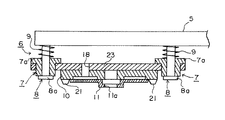
次に、本発明の第2実施例について説明する。
図3は第2実施例のフローティング機構の要部断面側面図である。
第2実施例では、チャッキングプレート10をアーム5に取付けるフローティング機構6を上記実施例とは異なる構造としたものである。
すなわち、本実施例のフローティング機構6は、チャッキングプレート10が固着された支持板23に複数のガイドブッシュ7が貫通して固着され、これらのガイドブッシュ7にそれぞれ挿通されるガイドシャフト8の基端部がアーム5に固着され、上記各ガイドブッシュ7の鍔部7aとアーム5との間でガイドシャフト8の周囲にコイルスプリング9が巻装されている。
【0018】
また、ガイドシャフト8の先端部に設けられた鍔部8aがガイドブッシュ7の下端に係止されており、上記コイルスプリング9の付勢力に抗する力がチャッキングプレート10に作用した際には、ガイドブッシュ7がチャッキングプレート10とともにガイドシャフト8に沿って移動する。
したがって、本実施例のフローティング機構6においても、上記実施例と同様に、小径基板11に対して過度のストレスをかけることなく、マガジンに支持された小径基板11の傾きや高さ位置誤差を吸着時に吸収することが可能となり、精度の高い吸着が可能となる。
【0019】
更に、本発明の第3実施例について説明する。
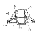
図4は第3実施例の要部断面側面図である。
本実施例では、チャッキングプレート10に設けられる複数の案内ピン21の代わりに受け部材25を設け、この受け部材25を案内部としたものである。
すなわち、図4に示すように、受け部材25は円筒部25aと底板25bを有し、底板25bの中央に設けられた穴25cにバキュームチューブ19が挿通され、バキュームチューブ19は受け部材25内の中央部に設けられたバキュームパッド26の内部に接続されている。
バキュームパッド26は、小径基板11の記録読取りエリヤNの内側部分で小径基板11の径方向に間隔を置いた箇所に接触可能に環状に形成された第1および第2内側接触部26A,26Bと、前記第1、第2内側接触部26A,26Bの間に形成され、各内側接触部26A,26Bがそれぞれ小径基板11の記録読取りエリヤNの内側部分に接触した状態で、前記各内側接触部26A,26Bと小径基板11の記録読取りエリアNの内側部分と協働して閉塞空間Kを形成する吸引用凹部27と、この吸引用凹部27と前記バキュームチューブ19とを接続する吸引路27Aとで構成されている。
【0020】
受け部材25の円筒部25aは小径基板11の略外径寸法に形成され、その先端面が受け部材25の基端に至り円筒部25aの中心側に傾斜するテーパ面25dに形成されている。
したがって、本実施例においては、小径基板11を吸着する場合には、小径基板11に接近する際に受け部材25のテーパ面25aにより、小径基板11が基準位置に案内されて位置決めされるとともに、小径基板11の傾きが水平に矯正され、これにより小径基板11の吸着精度が高められ、小径基板11の吸着保持が確実になされる。
尚、このような第3実施例に、第1,第2実施例におけるフローティング機構6を適用できることは無論のことであり、適用するか否かは任意である。
【0021】
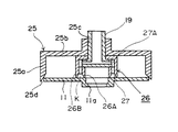
次に、本発明の第4実施例について説明する。
図5は第4実施例の要部断面側面図である。
本実施例では、上記第3実施例の受け部材25の形状を円錐形状にしたものである。
すなわち、バキュームチューブ19の先端部に円筒状の連結部材29を介してバキュームパッド26が連結され、連結部材29に受け部材28の基端部が固着されている。
受け部材28は、円錐状(ラッパ状)に形成されて先端側が開き、この開口部分が小径基板11の外径よりも大きな径に形成され、円錐状の内面がテーパ面28aとなっている。
したがって、小径基板11を吸着する場合には、小径基板11に接近する際に受け部材28のテーパ面28aにより、小径基板11が案内されて位置決めされるとともに、小径基板11の傾きが水平に矯正され、上記第3実施例と同様な効果が得られる。
【0022】
【発明の効果】
以上説明したように本発明によれば、円板状記録媒体の中央部および周縁部に吸着部の接触部が接触して円板状記録媒体を吸着するので、従来のような中央部分のみを吸着する場合に比べて吸引面積が大きくなり、円板状記録媒体が小径化しても確実に吸着することができる。
また、吸着部に案内部を設けたので、円板状記録媒体に接近する際に案内部により円板状記録媒体を位置決めし、円板状記録媒体の吸着位置精度を高めることができる。
更に、吸着部とアームとの間にフローティング機構を設けたので、マガジンに支持された円板状記録媒体の傾きや高さ位置誤差を吸着時に吸収することが可能となり、精度の高い吸着が可能となる。
【図面の簡単な説明】
【図1】第1実施例に係る真空吸着装置の要部断面側面図である。
【図2】チャッキングプレートの断面側面図である。
【図3】第2実施例の要部断面側面図である。
【図4】第3実施例の要部断面側面図である。
【図5】第4実施例の要部断面側面図である。
【符号の説明】
1…真空吸着装置
5…アーム
6…フローティング機構
7…ガイドブッシュ
8…ガイドシャフト
9…コイルスプリング
10…吸着部
11…小径基板
12…吸引用凹部
14、15…接触部
21、25、28…案内部
21a、25d、28a…テーパ面
K…閉塞空間[0001]
[Industrial application fields]
The present invention relates to a disk-shaped recording medium vacuum suction device for sucking a disk-shaped recording medium such as a small-diameter optical disk or a magnetic disk.
[0002]
[Prior art]
2. Description of the Related Art Conventionally, in various processes such as moving an optical disk or a magnetic disk or forming a film, a vacuum adsorption type handling device that adsorbs the optical disk or the magnetic disk is used.
This type of handling apparatus is provided with a vacuum pad that attracts an optical disk or a magnetic disk, and the optical disk or magnetic disk is attracted and transferred by the vacuum pad.
Further, in the conventional handling apparatus, the vacuum pad is formed so as to attract the central portion inside the film formation area (recording area) provided on the optical disk or magnetic disk. The inner center of the recording area is attracted by a vacuum pad and various operations are performed to prevent scratches and dirt from being deposited on the optical disk and magnetic disk deposition area (recording area) by the vacuum pad. ing.
This is not limited to optical disks and magnetic disks, but is also performed on various disc-shaped recording media that are vulnerable to scratches and dirt.
[0003]
[Problems to be solved by the invention]
However, in recent years, the diameter of optical disks and magnetic disks has been reduced, and with such a reduction in diameter, the area that can be contacted has become smaller and the adsorption area has become smaller.
For this reason, in the method of adsorbing only the central portion of a disk-shaped recording medium such as an optical disk or a magnetic disk like a conventional vacuum pad, the adsorbing force to the disk-shaped recording medium is reduced, and disk-shaped recording is performed. There is a fear that the handling reliability of the medium is lowered.
Therefore, in the present invention, even when a disk-shaped recording medium such as an optical disk or a magnetic disk is reduced in diameter and the adsorption area of the central portion is small, the disk-shaped recording medium can be reliably adsorbed and the adsorption accuracy can be further improved. The object is to provide a vacuum suction device .
[0005]
[Means for Solving the Problems]
In order to achieve the above object, the present invention provides a disc-shaped recording medium comprising a movable arm and a suction portion provided on the arm, and sucking and transferring the disc-shaped recording medium by the suction portion. In the vacuum suction device, the suction portion includes an inner contact portion that contacts an inner portion of a recording area of the disc-shaped recording medium, an outer contact portion that contacts an outer portion of the recording area of the disc-shaped recording medium, and the inner side The inner contact portion and the outer contact portion are formed between the contact portion and the outer contact portion, and the inner contact portion and the outer contact portion are in contact with the inner portion and the outer portion of the recording area of the disc-shaped recording medium, respectively. And a suction recess that forms a closed space in cooperation with a recording area portion of the disc-shaped recording medium, and a vacuum suction path that communicates with the suction recess.
Further, the present invention is characterized in that a guide portion that has a tapered surface that reaches the tip and slopes radially outward is provided outside the suction portion and can contact the periphery of the disk-shaped recording medium. To do.
[0006]
Further, the present invention provides a disk-like recording medium vacuum suction device that includes a movable arm and a suction part provided on the arm, and sucks and transfers the disk-like recording medium by the suction part. The adsorbing portion includes first and second inner contact portions formed in an annular shape so as to be able to come into contact with a radially spaced portion of the disc-shaped recording medium at an inner portion of the recording area of the disc-shaped recording medium; The first and second inner contact portions are formed between the first and second inner contact portions, and the first and second inner contact portions are in contact with the inner portion of the recording area of the disk-shaped recording medium. A suction recess that forms a closed space in cooperation with the contact portion and an inner portion of the recording area of the disk-shaped recording medium, a vacuum suction path that communicates with the suction recess, and an outer side of the suction portion. Periphery of a disk-shaped recording medium having a tapered surface that reaches the tip and inclines radially outward Characterized by comprising a contact capable guide.
[0007]
According to the present invention, a floating mechanism is provided between the arm and the suction portion so as to support the suction portion with respect to the arm so as to be movable along the central axis direction of the disk-shaped recording medium. It is characterized by that.
In the present invention, the floating mechanism includes a cylindrical guide bush penetratingly fixed to the arm, a base end portion inserted into the guide bush and locked to the guide bush, and the suction portion at the distal end portion. It comprises a guide shaft to be attached, and an urging member interposed between the arm and the suction portion.
In the present invention, the floating structure includes a cylindrical guide bush that is penetrated and fixed to the suction portion, a distal end portion that is inserted into the guide bush and locked to the guide bush, and a proximal end portion that is connected to the arm. It consists of a fixed guide shaft and an urging member interposed between the arm and the suction portion.
[0008]
Further, the present invention is configured by a plurality of guide pins attached to the suction portion, the guide portion having a tapered surface formed so as to be tapered toward the tip and capable of contacting the periphery of the disk-shaped recording medium. It is characterized by being.
Further, the present invention is characterized in that the guide portion is formed of a cylindrical receiving member attached to the suction portion having a tapered surface capable of contacting the periphery of the disc-shaped recording medium. .
Further, the present invention is characterized in that the guide part is constituted by a conical receiving member attached to the suction part, having a conical surface capable of contacting the periphery of the disc-shaped recording medium. .
[0009]
[Action]
Since the contact part of the suction part comes into contact with the central part and the peripheral part of the disk-shaped recording medium and is sucked, the suction area is larger than in the case of sucking only the central part as in the prior art, and disk-like recording. Even if the medium is reduced in diameter, it can be reliably adsorbed.
Further, when the suction part is provided on the arm and the guide part is provided on the suction part, the disk-shaped recording medium can be positioned by the guide part, and the suction position accuracy of the disk-shaped recording medium can be improved. The suction recording and holding of the recording medium can be performed reliably.
Furthermore, if a suction part is provided on the arm and a floating mechanism is provided between the suction part and the arm, when a disk-shaped recording medium is suctioned from a state where there is an inclination or height position error with respect to the suction part, Tilt and height position errors of the plate-shaped recording medium can be absorbed at the time of suction, and high-precision suction is possible.
[0010]
【Example】
A first embodiment of the present invention will be described below with reference to the drawings.
FIG. 1 is a cross-sectional side view of a main part of a vacuum suction device for a disk-shaped recording medium according to the present embodiment, and FIG. 2 is a cross-sectional side view of a chucking plate. A case of adsorbing a disc-shaped recording medium (hereinafter referred to as a small-diameter substrate) will be described.
As shown in FIG. 1, the vacuum suction device 1 of the present embodiment includes a transfer device 2 and a disk-shaped chucking plate (suction portion) 10 attached to the transfer device 2. .
The transfer device 2 includes a
The
[0011]
The
Each of the
Each of the
Therefore, the chucking
[0012]
The chucking
That is, in general, a recording / reading area N is formatted for recording / reading on a small-diameter substrate 11 such as an optical (magnetic) disk, as shown in FIG. A contact-prohibited area is formed, and a film in angstrom units is formed on the recording / reading area N.
In the present embodiment, the
[0013]
An annular contact surface (inner contact portion) 14 that contacts the central portion of the small-diameter substrate 11 excluding the recording / reading area N is provided at the central portion of the chucking
Then, in a state where the annular contact surfaces 14 and 15 are in contact with the central portion and the peripheral portion of the small-diameter substrate 11 excluding the recording / reading area N, the contact surfaces 14 and 15, the
Further, an
Further, the
The guide pins 21 are provided at equal intervals at three or more locations in the circumferential direction of the chucking
[0014]
Next, a case where the small-diameter substrate 11 is sucked and taken out by the vacuum suction device 1 will be described.
A plurality of small-diameter substrates 11 are stacked and stocked on the
The small-diameter substrate 11 stocked in such a pole-type magazine has a positional error on a plane due to the inclination of the
Further, since the stacking is performed, the integrated height varies from the total thickness error of the small-diameter substrate 11.
Furthermore, the actual situation is that some inclination occurs due to conveyance on a conveyor or a carriage with vibration in a stacked state.
[0015]
When the small-diameter substrate 11 in such a state is adsorbed and taken out from the pole-type magazine, the
Further, when the chucking
At this time, vacuum suction is performed by a vacuum pump, whereby the small-diameter substrate 11 is adsorbed to the chucking
[0016]
Therefore, in such a vacuum suction apparatus 1, the contact surfaces 14 and 15 of the chucking
Further, since a plurality of guide pins 21 having tapered surfaces 21 a are provided on the periphery of the chucking
In addition, since the chucking
Further, since the chucking
[0017]
Next, a second embodiment of the present invention will be described.
FIG. 3 is a sectional side view of an essential part of the floating mechanism of the second embodiment.
In the second embodiment, the floating
That is, in the floating
[0018]
Further, a flange 8a provided at the tip of the
Therefore, also in the floating
[0019]
Furthermore, a third embodiment of the present invention will be described.
FIG. 4 is a sectional side view of an essential part of the third embodiment.
In this embodiment, a receiving
That is, as shown in FIG. 4, the receiving
The
[0020]
The cylindrical portion 25a of the receiving
Therefore, in this embodiment, when the small-diameter substrate 11 is adsorbed, the small-diameter substrate 11 is guided and positioned at the reference position by the tapered surface 25a of the receiving
Of course, the floating
[0021]
Next, a fourth embodiment of the present invention will be described.
FIG. 5 is a sectional side view of an essential part of the fourth embodiment.
In this embodiment, the shape of the receiving
That is, the
The receiving
Therefore, when the small-diameter substrate 11 is attracted, the small-diameter substrate 11 is guided and positioned by the tapered surface 28a of the receiving
[0022]
【The invention's effect】
As described above, according to the present invention, since the contact portion of the suction portion comes into contact with the central portion and the peripheral portion of the disk-shaped recording medium and sucks the disk-shaped recording medium, Compared to the case of adsorption, the suction area becomes larger, and even if the disk-shaped recording medium is reduced in diameter, it can be reliably adsorbed.
Further, since the guide part is provided in the suction part, the disk-like recording medium can be positioned by the guide part when approaching the disk-like recording medium, and the suction position accuracy of the disk-like recording medium can be improved.
In addition, since a floating mechanism is provided between the suction part and the arm, it is possible to absorb the tilt and height position error of the disk-shaped recording medium supported by the magazine during suction, enabling highly accurate suction. It becomes.
[Brief description of the drawings]
FIG. 1 is a cross-sectional side view of an essential part of a vacuum suction device according to a first embodiment.
FIG. 2 is a cross-sectional side view of a chucking plate.
FIG. 3 is a sectional side view of an essential part of a second embodiment.
FIG. 4 is a sectional side view of an essential part of a third embodiment.
FIG. 5 is a sectional side view of an essential part of a fourth embodiment.
[Explanation of symbols]
1 ...
Claims (9)
このアームに設けられた吸着部とを備え、With a suction part provided on this arm,
円板状記録媒体を前記吸着部により吸着して移送する円板状記録媒体の真空吸着装置において、In the vacuum suction device for a disk-shaped recording medium that sucks and transfers the disk-shaped recording medium by the suction section,
前記吸着部は、The adsorption part is
円板状記録媒体の記録エリアの内側部分に接触する内側接触部と、An inner contact portion that contacts an inner portion of the recording area of the disk-shaped recording medium;
円板状記録媒体の記録エリアの外側部分に接触する外側接触部と、An outer contact portion that contacts an outer portion of the recording area of the disk-shaped recording medium;
前記内側接触部と外側接触部の間に形成され、各内側接触部と外側接触部がそれぞれ円板状記録媒体の記録エリアの内側部分と外側部分に接触した状態で、前記内側接触部と外側接触部と円板状記録媒体の記録エリア部分と協働して閉塞空間を形成する吸引用凹部と、The inner contact portion and the outer contact portion are formed between the inner contact portion and the outer contact portion, and the inner contact portion and the outer contact portion are in contact with the inner and outer portions of the recording area of the disc-shaped recording medium, respectively. A suction recess that forms a closed space in cooperation with the contact portion and the recording area portion of the disc-shaped recording medium;
前記吸引用凹部に連通する真空吸引路と、A vacuum suction path communicating with the suction recess;
を備えたことを特徴とする円板状記録媒体の真空吸着装置。A vacuum suction device for a disk-shaped recording medium, comprising:
このアームに設けられた吸着部とを備え、With a suction part provided on this arm,
円板状記録媒体を前記吸着部により吸着して移送する円板状記録媒体の真空吸着装置において、In the vacuum suction device for a disk-shaped recording medium that sucks and transfers the disk-shaped recording medium by the suction section,
前記吸着部は、The adsorption part is
円板状記録媒体の記録エリアの内側部分で円板状記録媒体の径方向に間隔を置いた箇所に接触可能に環状に形成された第1および第2内側接触部と、First and second inner contact portions formed in an annular shape so as to be able to come into contact with portions spaced in the radial direction of the disk-shaped recording medium at an inner portion of the recording area of the disk-shaped recording medium;
前記第1、第2内側接触部の間に形成され、各第1、第2内側接触部がそれぞれ円板状記録媒体の記録エリアの内側部分に接触した状態で、各第1、第2内側接触部と円板状記録媒体の記録エリアの内側部分と協働して閉塞空間を形成する吸引用凹部と、The first and second inner contact portions are formed between the first and second inner contact portions, and the first and second inner contact portions are in contact with the inner portion of the recording area of the disk-shaped recording medium. A suction recess that forms a closed space in cooperation with the contact portion and the inner portion of the recording area of the disk-shaped recording medium;
前記吸引用凹部に連通する真空吸引路と、A vacuum suction path communicating with the suction recess;
前記吸着部の外側に設けられ、先端に至り径方向外方に傾斜するテーパ面を有し円板状記録媒体の周縁に接触可能な案内部と、A guide portion that is provided on the outside of the suction portion and has a tapered surface that reaches the tip and inclines radially outward, and can contact the periphery of the disk-shaped recording medium;
を備えたことを特徴とする円板状記録媒体の真空吸着装置。A vacuum suction device for a disk-shaped recording medium, comprising:
Priority Applications (1)
| Application Number | Priority Date | Filing Date | Title |
|---|---|---|---|
| JP03184294A JP3674635B2 (en) | 1994-02-02 | 1994-02-02 | Vacuum suction device for disk-shaped recording media |
Applications Claiming Priority (1)
| Application Number | Priority Date | Filing Date | Title |
|---|---|---|---|
| JP03184294A JP3674635B2 (en) | 1994-02-02 | 1994-02-02 | Vacuum suction device for disk-shaped recording media |
Publications (2)
| Publication Number | Publication Date |
|---|---|
| JPH07215461A JPH07215461A (en) | 1995-08-15 |
| JP3674635B2 true JP3674635B2 (en) | 2005-07-20 |
Family
ID=12342313
Family Applications (1)
| Application Number | Title | Priority Date | Filing Date |
|---|---|---|---|
| JP03184294A Expired - Fee Related JP3674635B2 (en) | 1994-02-02 | 1994-02-02 | Vacuum suction device for disk-shaped recording media |
Country Status (1)
| Country | Link |
|---|---|
| JP (1) | JP3674635B2 (en) |
-
1994
- 1994-02-02 JP JP03184294A patent/JP3674635B2/en not_active Expired - Fee Related
Also Published As
| Publication number | Publication date |
|---|---|
| JPH07215461A (en) | 1995-08-15 |
Similar Documents
| Publication | Publication Date | Title |
|---|---|---|
| US8873200B2 (en) | Spinstands for testing a head gimbal assembly | |
| CN1178219C (en) | Disk holder | |
| WO1998036867A1 (en) | Method and apparatus for laser texturing a magnetic recording disk substrate | |
| JP3674635B2 (en) | Vacuum suction device for disk-shaped recording media | |
| US20030112553A1 (en) | Apparatus and method of disc clamping for disc stack assembly | |
| CN101366087A (en) | disk device | |
| JP2783104B2 (en) | Centering lamination device | |
| JP6154617B2 (en) | Disc clamp mechanism, recording / reproducing apparatus, and disc changer | |
| EP1341171A2 (en) | Disk insertion position setting device | |
| JP3112272B2 (en) | Disk peripheral surface processing equipment | |
| JPH07296429A (en) | Disc-shaped recording medium handling device | |
| JPH10134427A (en) | Method for taking up memory disk from holding base and holding base used for the purpose | |
| JP4250605B2 (en) | Disk stacking method and disk stacking apparatus | |
| JPH0264960A (en) | Disk positioning device | |
| JPS61180988A (en) | Sucking head holding recording medium and its separator | |
| KR19980071557A (en) | Disc drive | |
| JPH077506B2 (en) | Disc handling chuck mechanism | |
| JP3643733B2 (en) | Inspection object positioning device | |
| JPH0119263Y2 (en) | ||
| JP2005310281A (en) | Disk unit | |
| JPH10134423A (en) | Method for taking up memory disk from holding base and device therefor | |
| JP2003223755A (en) | Disk device and disk alignment mechanism | |
| CN121604777A (en) | Centering mechanism, bonding equipment and centering method | |
| JPH087531A (en) | Disk drive device | |
| JPH1166718A (en) | Turntable for disk-shaped recording media |
Legal Events
| Date | Code | Title | Description |
|---|---|---|---|
| A131 | Notification of reasons for refusal |
Free format text: JAPANESE INTERMEDIATE CODE: A131 Effective date: 20050209 |
|
| A521 | Written amendment |
Free format text: JAPANESE INTERMEDIATE CODE: A523 Effective date: 20050311 |
|
| TRDD | Decision of grant or rejection written | ||
| A01 | Written decision to grant a patent or to grant a registration (utility model) |
Free format text: JAPANESE INTERMEDIATE CODE: A01 Effective date: 20050406 |
|
| A61 | First payment of annual fees (during grant procedure) |
Free format text: JAPANESE INTERMEDIATE CODE: A61 Effective date: 20050419 |
|
| LAPS | Cancellation because of no payment of annual fees |