JP3673329B2 - Substrate processing apparatus and cleaning method - Google Patents
Substrate processing apparatus and cleaning method Download PDFInfo
- Publication number
- JP3673329B2 JP3673329B2 JP17634896A JP17634896A JP3673329B2 JP 3673329 B2 JP3673329 B2 JP 3673329B2 JP 17634896 A JP17634896 A JP 17634896A JP 17634896 A JP17634896 A JP 17634896A JP 3673329 B2 JP3673329 B2 JP 3673329B2
- Authority
- JP
- Japan
- Prior art keywords
- cleaning
- substrate
- processing
- timing
- cleaning means
- Prior art date
- Legal status (The legal status is an assumption and is not a legal conclusion. Google has not performed a legal analysis and makes no representation as to the accuracy of the status listed.)
- Expired - Fee Related
Links
Images


Description
【0001】
【発明の属する技術分野】
本発明は、半導体ウエハや液晶表示器のガラス基板等の各種基板の製造に適用される基板処理装置および洗浄方法に関するものである。
【0002】
【従来の技術】
従来から、半導体ウエハや液晶表示器のガラス基板等を製造する装置として、例えば、処理前の基板を洗浄する基板洗浄ユニットと、基板にフォトレジスト液の薄膜を形成するスピンコーター等のコーターユニットと、スピンコーターで形成された薄膜のうち基板縁部の不要な薄膜を除去する端縁処理ユニットと、端縁部の不要な薄膜が除去された基板面のフォトレジスト液を乾燥させるベークユニット等とを備え、搬送用のロボットによって基板を各ユニット間で搬送しながら処理を施すような基板処理装置が一般に知られている。
【0003】
このような基板処理装置において、上記コーターユニットや端縁処理ユニットでは、その処理過程でフォトレジスト液供給用のノズル等、装置各部にフォトレジスト液が付着し、これが乾燥してパーティクル発生の原因の一つとなることから、フォトレジスト液が付着する箇所に対して洗浄液を噴射する洗浄装置を設け、これによってフォトレジスト液を洗浄、除去することが行われている。
【0004】
【発明が解決しようとする課題】
ところが、従来の基板処理装置においては、上記のような洗浄装置が予め設定された所定枚数の基板毎に作動させられるのが一般的であり、例えば、何らかの原因で基板の搬送が中断、あるいは停止されると、洗浄装置が長期間作動しないために付着したフォトレジスト液が乾燥してパーティクルが発生したり、あるいは付着したレジスト液の除去が著しく困難になるといった問題があった。
【0005】
また、複数の洗浄装置を設ける場合、フォトレジスト液の付着量や、付着したフォトレジスト液を除去するのに要する時間等は、フォトレジスト液が付着する部分や、各洗浄装置の洗浄能力等によって大きく異なるため、各種洗浄装置を一律に同じ条件で作動させるのでは、パーティクルの発生を効果的に防止する上でも、また基板の処理効率を確保する上でも必ずしも十分ではない。
【0006】
本発明は、上記問題を解決するためになされたものであり、基板の処理状況等に応じた適切なタイミングで洗浄装置を作動させることにより、基板の処理効率を確保しつつパーティクルの発生を確実に防止することができる基板処理装置および洗浄方法を提供することを目的としている。
【0007】
【課題を解決するための手段】
本発明の基板処理装置は、複数の処理部に基板を搬出入しながら処理を施すことにより基板表面に薄膜を形成するとともに、処理により装置へ付着した不要な付着物を洗浄除去する複数の洗浄手段を備えた基板処理装置において、上記各洗浄手段の作動タイミングをそれぞれ設定可能にするタイミング設定手段と、このタイミング設定手段で設定された作動タイミングで上記各洗浄手段をそれぞれ作動させる洗浄制御手段とを具備し、上記作動タイミングが、当該洗浄手段が備えられる処理部より上流側の処理部における基板の処理状況に応じたタイミングに設定されているものである(請求項1)。
【0008】
また、複数の処理部に基板を搬出入しながら処理を施すことにより基板表面に薄膜を形成するとともに、処理により装置へ付着した不要な付着物を洗浄除去する複数の洗浄手段を備えた基板処理装置において、上記各洗浄手段の作動タイミングをそれぞれ設定可能にするタイミング設定手段と、このタイミング設定手段で設定された作動タイミングで上記各洗浄手段をそれぞれ作動させる洗浄制御手段とを具備し、上記作動タイミングが、基板処理装置の稼働中であって、当該洗浄手段が備えられる処理部への基板の搬入遅れ量に応じたタイミングに設定されているものである(請求項2)。
【0009】
これらの装置によれば、各洗浄手段の作動タイミングを基板の処理状況、各洗浄手段の機能、あるいは洗浄箇所等に応じた適切なタイミングで作動させることが可能となり、特に作動タイミングとして上記の各タイミングが設定されることにより基板の処理効率を確保しつつパーティクルの発生を効果的に防止することが可能となる。
【0010】
これらの装置において、上記タイミング設定手段は、上記作動タイミングとして、(1)当該洗浄手段が備えられる処理部より上流側の処理部における基板の処理状況に応じたタイミング、(2)基板処理装置の稼働中であって、当該洗浄手段が備えられる処理部への基板の搬入遅れ量に応じたタイミング、(3)基板処理装置の稼働時及び停止時の少なくとも一方に応じたタイミング、(4)基板処理装置の稼働中であって非処理状態の発生に応じたタイミングのうち少なくとも(1)のタイミングを含む複数のタイミングを設定可能にされているもの(請求項3)、あるいは少なくとも(2)のタイミングを含む複数のタイミングを設定可能にされているものであるのが好ましい(請求項4)。
【0011】
これらの装置によると、各洗浄手段を基板の処理状況や各洗浄手段の機能等に適したより良いタイミングで作動させることができるとともに、そのようなタイミング設定を容易に行うことが可能となる。
【0012】
なお、請求項3および請求項4の記載において「稼働時及び停止時」とは、いわゆる電源のオンオフ時に限られず、基板処理装置へ基板が搬入された時から全ての基板の処理が終了して基板が基板処理装置外へ搬出された後までを含む意味である。
【0013】
さらに、洗浄手段を複数の作動条件から選択的に作動させるように上記洗浄制御手段を構成すれば(請求項5)、各洗浄手段の機能、あるいは洗浄箇所等に応じて洗浄処理を行うことができるとともに、基板の処理タクトに影響を与えない範囲で最大限の時間を有効に利用して洗浄を行うことが可能となる。
【0014】
特に、処理部として、回転テーブル上に保持される基板の表面にノズル部材を介して液体を供給して基板の回転に伴う遠心力により基板表面に薄膜を形成する薄膜形成部を有し、上記洗浄手段として、上記ノズル部材を洗浄するノズル洗浄手段と、回転テーブルを洗浄する回転テーブル洗浄手段と、回転テーブル周辺を洗浄する周辺部洗浄手段とを有する基板処理装置や(請求項6)、あるいは、処理部として、搬送手段により処理テーブル上に移載される薄膜形成後の基板を位置決め部材により位置決めして基板端縁に形成された不要な薄膜を除去する端縁除去部を有し、上記洗浄手段として、上記位置決め部材を洗浄する位置決め部材洗浄手段と、上記処理テーブルを洗浄する処理テーブル洗浄手段とを有する基板処理装置(請求項7)においては、薄膜形成のための液体が頻繁に装置に付着するため、このような基板処理装置について上記請求項1〜5の構成を採用するようにすれば、基板の処理効率の確保及びパーティクル発生防止を通じて基板の生産性の向上及び品質の向上を図ることが可能となる。
【0015】
なお、より具体的な構成として、基板処理装置は、基板を保持するテーブルと、このテーブル上に保持された基板の表面に液体を供給するノズル部材とを備え、上記洗浄手段として前記ノズル部材を洗浄するノズル洗浄手段を備えているものであってもよい(請求項8)。
【0016】
一方、本発明に係る洗浄方法は、複数の処理部に基板を搬出入しながら処理を施すことにより基板表面に薄膜を形成するとともに、処理により装置へ付着した不要な付着物を洗浄除去する複数の洗浄手段を備えた基板処理装置の前記処理部の洗浄方法であって、前記各洗浄手段の作動タイミングをそれぞれ洗浄手段が備えられる処理部より上流側の処理部における基板の処理状況に応じたタイミングに予め設定しておき、この作動タイミングで各洗浄手段をそれぞれ作動させることにより前記各処理部を洗浄するようにしたものである(請求項9)。
【0017】
また、本発明に係る別の洗浄方法は、複数の処理部に基板を搬出入しながら処理を施すことにより基板表面に薄膜を形成するとともに、処理により装置へ付着した不要な付着物を洗浄除去する複数の洗浄手段を備えた基板処理装置の前記処理部の洗浄方法であって、前記各洗浄手段の作動タイミングをそれぞれ基板処理装置の稼働中であって、当該洗浄手段が備えられる処理部への基板の搬入遅れ量に応じたタイミングに予め設定しておき、この作動タイミングで各洗浄手段をそれぞれ作動させることにより前記各処理部を洗浄するようにしたものである(請求項10)。
【0018】
なお、上記各請求項の記載において「洗浄」とは、純水や洗浄剤等を用いて汚れを洗い落とすいわゆる洗浄以外に、付着した異物を掃き取ったり、あるいは吸い取ったりするいわゆる清掃をも含む意味である。
【0019】
【発明の実施の形態】
本発明の実施の形態について図面を用いて説明する。
【0020】
図1は、本発明が適用される基板処理装置の一例を概略的に示している。同図に示すように、基板処理装置10には、上流側(同図では左方側)から順に、基板の搬入部となるローダ11、基板を一時的に保持する待機ユニット12、フォトレジスト液による薄膜形成のためのコーターユニット14、基板端縁の不要な薄膜除去のための端縁処理ユニット16、乾燥処理のためのベークユニット18及び基板の搬出部となるアンローダ19が配設されており、上記ローダ11に投入されるカセットから基板を取出し、その基板を搬送ロボット20〜22により各ユニット間で順次搬送しながら処理を施してアンローダ19にセットされるカセットに収納して搬出するように構成されている。そして、この基板処理装置10において、本発明はコーターユニット14及び端縁処理ユニット16について適用されている。
【0021】
上記コーターユニット14は、角形基板を回転させながらその表面にフォトレジスト液の薄膜を形成するスピンコーターで、図2及び図3に示すように、コーターユニット14の基台上に設けられる基板保持部30と、その上方に昇降可能に支持される蓋部31と、後記回転テーブル32の吸着部33を清掃するテーブルクリーナー75とから構成されている。
【0022】
基板保持部30は、基板Wを保持する角形の回転テーブル32と、回転テーブル32の周囲を覆うカップ34と、フォトレジスト液を基板Wの表面に供給する液供給装置35とを備えている。
【0023】
上記回転テーブル32は、モータ32aにより回転駆動されるとともに、その中央部には、基板Wを真空吸着する吸着部33が設けられており、この吸着部33が図外のエアシリンダの駆動により昇降するように構成されている。そして、基板Wの搬入出時には、回転テーブル32のうち吸着部33のみが昇降させられて基板Wの受渡しが行われる一方、処理時には、吸着部33が回転テーブル32と一体に回転することにより基板Wを回転させるように構成されている。
【0024】
上記液供給装置35には、一軸方向に延びるスリット状のノズル38が設けられ、このノズル38が上記回転テーブル32の上方において上記一軸方向と直交する方向に移動可能とされている。すなわち、上記カップ34の側部には互いに平行に延びる一対のレール39とモータ36aの作動により回転するボールねじ軸36bとが配設され、上記レール39に支持部材37がスライド自在に装着され、この支持部材37に上記ノズル38が取付けられるとともに、この支持部材37のナット部分が上記ボールねじ軸36bに螺合している。
【0025】
そして、処理時には、上記モータ36aの作動によるボールねじ軸36bの回転に応じてノズル38が支持部材37と一体に移動させられ、回転テーブル32上方の所定の供給位置にセットされた状態でノズル38から一定量のフォトレジスト液を基板Wの表面に供給するようになっている。
【0026】
一方、このような液供給時以外のときには支持部材37がカップ34外方の退避位置(図4の実線に示す位置)に保持されるとともに、必要に応じてこの退避位置よりもさらに外方の洗浄位置(図4の二点鎖線に示す位置)に配置されるようになっている。
【0027】
上記退避位置には、図4及び図5に示すように、乾燥防止溶剤を貯留した溶剤ポット40がエアシリンダ41により上下動可能に支持されている。そして、支持部材37が退避位置にセットされた状態では、この溶剤ポット40が上昇端位置に保持されてノズル38が溶剤雰囲気中に介在させられ、これによってノズル38のフォトレジスト液の乾燥が防止されるようになっている。
【0028】
上記洗浄位置には、上記ノズル38に付着したフォトレジスト液を洗浄除去するためのノズル洗浄装置42が設けられている。ノズル洗浄装置42には、洗浄ヘッド43が設けられ、この洗浄ヘッド43がノズル38に沿って往復動可能となっている。すなわち、上記洗浄位置には、図6に示すようにノズル38の下方に、ノズル38と平行に延びるレール44とモータ46の駆動により回転するボールねじ軸45とが設けられ、上記洗浄ヘッド43がレール44にスライド可能に装着されるとともに洗浄ヘッド43のナット部分がボールねじ軸45に螺合している。これによりモータ46の正逆回転駆動に応じて洗浄ヘッド43がノズル38の一端側外方に位置にする原点位置(図6の実線に示す位置)からレール44に沿って往復移動するようになっている。
【0029】
洗浄ヘッド43は、図7及び図8に示すように、ノズル38を介在可能とする断面U字型の容器からなり、その内部に、リンス弁47a及びN2弁47bを介して図外の洗浄剤(以下、リンスという)供給源及びN2供給源に接続され、ノズル38の両側に突設される複数の洗浄ノズル47と、洗浄後のリンスを外部排出するための排出ダクト48とを備えた構成となっている。つまり、洗浄ノズル47からリンス及びN2ブローが噴射されながら洗浄ヘッド43がノズル38に沿って往復移動させられることにより、ノズル38に付着したフォトレジスト液が除去されるようになっている(以下、この洗浄をノズル洗浄という)。
【0030】
上記蓋部31は、図3に示すように、昇降可能に支持される本体50の下部に円盤状のプレート51が回転自在に支持された構成とされ、本体50が所定高さ位置まで下降させられることにより蓋部31が基板保持部30に合体、すなわちプレート51が基板保持部30のカップ34内に介在し、所定の隙間を形成した状態で回転テーブル32と係合するように構成されている。そして、処理時には、回転テーブル32上の基板Wをプレート51で覆った状態で、回転テーブル32とプレート51とが一体に回転させられるようになっている。
【0031】
ところで、上記スピンコーターの基板保持部30及び蓋部31には、その処理に際して回転テーブル32やカップ34に付着するフォトレジスト液を洗浄除去するための複数の洗浄ノズルが設置されており、必要に応じて回転テーブル32を回転させながらこれらの各洗浄ノズルからリンスを噴射することによって基板保持部30及び蓋部31の各部の洗浄(以下、この洗浄をカップ洗浄という)を行うように構成されている。
【0032】
具体的には、図3及び図9に示すように、基板保持部30に、外周リンスノズル55、カップリンスノズル56、バックリンスノズル57、トラップリンスノズル58及び排気口リンスノズル59といった5種類の洗浄ノズルが設けられている。また、図10に示すように、蓋部31に第1プレートリンスノズル65(以下、第1PRノズル65という)、チャックリンスノズル66及び第2プレートリンスノズル67(以下、第2PRノズル66という)といった3種類の洗浄ノズルが設けられている。
【0033】
上記外周リンスノズル55は、正確には基板保持部30の外部に設けられており、図外の駆動手段により上下方向及び水平方向に移動可能に支持されている。そして、通常はカップ34側方の退避位置にあり、洗浄時にのみノズル先端をカップ34内に臨ませる作動位置に移動させられて回転テーブル32の周縁部にリンスを噴射し、これによって回転テーブル32の周縁を洗浄するようになっている。
【0034】
上記カップリンスノズル56は、カップ34の内周面において、回転テーブル32の周縁部に対向する位置に設けられており、回転テーブル32の周縁部に向かってリンスを噴射し、回転テーブル32で跳ね返されるリンスでカップ34の内周面を洗浄するようになっている。
【0035】
上記バックリンスノズル57は、回転テーブル32の下面に対向する位置に設けられており、リンスを噴射することによって回転テーブル32の下面を洗浄するようになっている。
【0036】
上記トラップリンスノズル58は、回転テーブル32の下面において、その周縁部に対向する位置に設けられており、回転テーブル32の周縁部に形成されたレジスト排出口61に向けてリンスを噴射するようになっている。すなわち、回転テーブル32の周縁には、図9に示すように、遠心力で回転テーブル32周縁に溜るフォトレジスト液をカップ34内に形成された液貯留部62に導出するためのレジスト排出口61が形成されており、上記トラップリンスノズル58からのリンス噴射によりこのレジスト排出口61に付着したフォトレジスト液を除去するようになっている。
【0037】
上記排気口リンスノズル59は、回転テーブル32の下方に形成された排気通路64内にリンスを噴射するようになっている。つまり、回転テーブル32の下方には、図9に示すように上記液貯留部62に連通する排気通路64が設けられ、液貯留部62に溜ったフォトレジスト液のミストを含む雰囲気ガスがこの排気通路64及びこの排気通路64に接続される排気ダクト63を介して外部排出されるようになっている。また、液貯留部62に貯留されたフォトレジスト液やリンス液などは、ドレン52より排出するようになっている。
【0038】
第1PRノズル65及びチャックリンスノズル66は、図10に示すように、蓋部31の上記本体50の中心部分に一体に設けられている。これらのノズル65,66は、ノズル先端をプレート51の中心に形成された開口部51aから下方に突出させる作動位置と、プレート51上方の後記退避位置とに変位可能とされ、上記作動位置にある状態で、第1PRノズル65からプレート51の下面に、チャックリンスノズル66により回転テーブル32の周縁部表面にそれぞれリンスを噴射してプレート51の下面及び回転テーブル32の周縁部表面を洗浄するようになっている。
【0039】
ここで、第1PRノズル65及びチャックリンスノズル66は、図10及び図11に示すように、支持部材68を介してモータ69の出力軸に取付けられるとともに、エアシリンダ70によりモータ69と一体に上下方向に変位させられるようになっている。すなわち、洗浄終了後は、モータ69及びエアシリンダ70の駆動により、各ノズル65,66が上記作動位置からプレート51上方の位置(図10の一点鎖線に示す位置)に移動させられ、さらに90°旋回させられることにより本体50の中心軸側方の退避位置(図11の一点鎖線に示す位置)に収納されるようになっている。そして、基板Wの処理時には、開口部51aの上方に昇降可能に支持された栓体71がエアシリンダ72の駆動により下降端位置に移動させられることにより、この開口部51aが塞がれるようになっている。
【0040】
上記第2PRノズル67は、上記本体50において、その中心部分より若干側方部分に設けられており、上記プレート51に向かってリンスを噴射することによりプレート51の上面を洗浄するようになっている。
【0041】
なお、上記基板保持部30の各ノズル55〜59は、それぞれリンス弁55a〜59aを介して図外のリンス供給源に接続されている。また、上記蓋部31の第2PRノズル67はリンス弁67aを介してリンス供給源に、第1PRノズル65及びチャックリンスノズル66は共にリンス弁65aを介してリンス供給源に接続されている。
【0042】
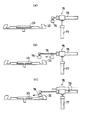
上記テーブルクリーナー75は、上記のようなリンス噴射による洗浄が好ましくない回転テーブル32の主に吸着部33を清掃するもので、図2及び図13(a)に示すように基板保持部30の側方に設置されている。
【0043】
テーブルクリーナー75は、清掃用のヘッド76と、このヘッド76を上下方向及び水平方向に移動させるエアシリンダ77,78とから構成されている。ヘッド76には、図12に示すように超音波発生器79aと図外の集塵用負圧発生器に接続されるバキュームノズル79bとが並設され、超音波発生器79aにより生成された超音波エアーを吸着部33表面に吹き付けることにより吸着部33上に付着した異物を剥離させ、この異物をバキュームノズル79bで吸引排出するように構成されている。
【0044】
そして、清掃時には、図13(a)に示すカップ34外部の初期位置からヘッド76が回転テーブル32の端部上方まで移動させられた後、回転テーブル32表面に所定の隙間を有して対向する位置まで下降させられ(図13(b),(c))、この状態でヘッド76が往復動させられることにより吸着部33の清掃が行われるようになっている(以下、この清掃を回転テーブル清掃という)。
【0045】
一方、上記端縁処理ユニット16は、図2に示すように、上記コーターユニット14での薄膜形成処理が完了した基板Wを真空吸着して保持する角形の処理テーブル80と、この処理テーブル80の周囲に配置される端縁処理装置81と、基板Wの位置決め装置82と、処理テーブル80表面を清掃するテーブルクリーナー90とを備えた構成となっている。
【0046】
上記処理テーブル80は、エアシリンダ等の駆動により上下動可能となっており、基板Wの搬入時には、搬送ロボット21により搬送される基板Wを上昇端位置で受け取り、下降端位置に設けられている上記端縁処理装置81の所定の作業位置にセットするように構成されている。すなわち、搬送ロボット21には接離可能な左右一対のハンド21aが設けられ、両ハンド21aにより基板Wの左右縁部が支持された状態で搬送される。そして、処理テーブル80上方に基板Wがセットされると、処理テーブル80が上昇端位置まで移動して基板Wを下方から支持するとともに、上記両ハンド21aが離間位置に変位させられ、その後、処理テーブル80が下降端位置まで移動することにより基板Wの受け渡しが行われるようになっている。
【0047】
上記各端縁処理装置81は、作業位置にセットされた基板Wの各コーナー部分に対応して4機設けられており、各端縁処理装置81がそれぞれ基板Wの各辺に沿って往復移動しながら、基板Wの端縁部に沿ってリンスを吹き付けることにより不要な薄膜を洗い落とすように構成されている。
【0048】
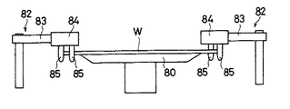
上記位置決め装置82は、処理テーブル80上に移載された基板Wの平面的な位置ずれを修正するもので、処理テーブル80の対角方向に一対設けられ、これらにより基板Wを対角方向両側から挾持することにより基板Wの位置決めを行うようになっている。すなわち、各位置決め装置82は、図外のモータの駆動により旋回するアーム83の先端にヘッド84を有し、このヘッド84に、下方に突出する一対の位置決めピン85を具備した構成となっている。そして、位置決め時には、図2及び図14に示すように、アーム83の旋回に応じて位置決めピン85を対角方向両側から基板Wのコーナー部分に当接させて基板Wの位置ずれを機械的に修正する一方、このような位置決め時以外は、処理テーブル80側方の退避位置にアーム83を収納するようになっている。
【0049】
各位置決め装置82には、上述のような基板Wの位置決めに伴い位置決めピン85に付着するフォトレジスト液を洗浄除去するためのピン洗浄装置86がそれぞれ設けられ、このピン洗浄装置86が上記退避位置に収納されたヘッド84の下方に対応する箇所に配置されている。
【0050】
ピン洗浄装置86には、図2及び図15(a)に示すように、位置決めピン85に対応する筒状の一対の洗浄ポット87が設けられ、これらの各洗浄ポット87の内部に、リンス弁87a及びN2弁87bを介してそれぞれリンス供給源及びN2供給源に連結される複数のノズルと、洗浄後のリンスを外部排出するための排出ダクトとが設けられているとともに、これらの洗浄ポット87が図外のエアシリンダの駆動により一体に上下動させられるように構成されている。
【0051】
そして、洗浄時には、位置決め装置82のアーム83が退避位置に収納された状態(図15(a)に示す状態)で洗浄ポット87が上昇位置にセットされることにより位置決めピン85が洗浄ポット87内に挿入され(図15(b))、この状態でリンス及びN2ブローが噴射されることにより位置決めピン85の洗浄が行われるようになっている(以下、この洗浄をピン洗浄という)。
【0052】
上記テーブルクリーナー90は、図2に示すように、ヘッド91と、このヘッド91を水平方向に移動させるエアシリンダ92とから構成されている。このテーブルクリーナー90は、ヘッド91を上下動させるエアシリンダが設けられていない点を除いては、上記コーターユニット14のテーブルクリーナー75と同一の構成であり、ヘッド91を処理テーブル80に対向させて移動させることにより処理テーブル80に付着した異物を剥離させながら吸引排出するようになっている(以下、これを処理テーブル清掃という)。なお、テーブルクリーナー90においてヘッド91を上下動させるエアシリンダが設けられていないのは、ヘッド91の処理テーブル80の清掃動作については、上記コーターユニット14のカップ34のような障害物が存在しないためである。
【0053】
以上のような基板処理装置10において、ローダ11のカセットから待機ユニット12に搬入された基板Wは、先ず、搬送ロボット20によりスピンコーターの回転テーブル32上に移載され、液供給装置35によりその表面にフォトレジスト液が塗布される。そして、基板保持部30と蓋部31とが合体された後、回転テーブル32と一体に回転させられることにより基板Wの表面にフォトレジスト液の薄膜が形成される。薄膜形成後は、搬送ロボット21により端縁処理ユニット16に搬送されて処理テーブル80上に移載されるとともに、位置決め装置82による位置決めが行われる。そして、端縁処理装置81の移動に伴い不要な薄膜部分が除去された後、搬送ロボット22によりベークユニット18に移載され、ベークユニット18において基板Wに対する加熱及び冷却処理が施されてアンローダ19のカセットに収納される。
【0054】
そして、このような基板Wに対する処理動作中に、所定のタイミングで上記ノズル洗浄装置42等の各種洗浄、あるいは清掃装置が作動されることにより、ノズル洗浄、カップ洗浄、回転テーブル清掃、ピン洗浄及び処理テーブル清掃が行われ、これにより基板Wの処理に伴いコーターユニット14及び端縁処理ユニット16の各部に付着するフォトレジスト液等が洗浄、除去されるようになっている。
【0055】
図16は、そのようなコーターユニット14及び端縁処理ユニット16の各洗浄及び清掃装置を制御する基板処理装置10の制御系を示している。なお、以下の説明では、特に区別する場合以外は、説明の便宜上洗浄と清掃を併せて単に洗浄と呼ぶことにする。
【0056】
同図に示すように、基板処理装置10には、その全体を統括的に制御する本体制御部100が設けられているとともに、コーターユニット14及び端縁処理ユニット16に、それぞれ各ユニット14,16を制御するコーターユニット制御部101及び端縁処理ユニット制御部111が設けられ、これらのコーターユニット制御部101及び端縁処理ユニット制御部111がそれぞれ本体制御部100に接続されている。
【0057】
コーターユニット制御部101には、コーターユニット14に搭載されるモータやエアシリンダ等の駆動源を統括的に制御する軸制御部103と、各リンス弁の開閉を制御するリンス弁制御部104と、各N2弁の開閉を制御するN2弁制御部105と、上記テーブルクリーナー75における超音波発生器79aの作動及びバキュームノズル79bの負圧発生とをそれぞれ制御する超音波発生器制御部106及び集塵用負圧発生制御部107とが接続されており、上記本体制御部100から出力される基板処理装置10の生産状況等に関する情報に基づいて、後に詳述するような洗浄モードに従ってノズル洗浄、カップ洗浄及び回転テーブル清掃を行うべく各駆動部等が上記各制御部103〜107を介してコーターユニット制御部101により制御されるようになっている。
【0058】
端縁処理ユニット制御部111にも、同様に、端面処理ユニット16に搭載されるモータやエアシリンダ等の駆動源を統括的に制御する軸制御部113と、各リンス弁の開閉を制御するリンス弁制御部114と、各N2弁の開閉を制御するN2弁制御部115と、上記テーブルクリーナー90における超音波発生器の作動及びバキュームノズルの負圧発生とをそれぞれ制御する超音波発生器制御部116及び集塵用負圧発生制御部117とが接続されており、後述の洗浄モードに従ってピン洗浄及び処理テーブル清掃を行うべく各駆動部等が上記各制御部113〜117を介して端縁処理ユニット制御部111により制御されるようになっている。
【0059】
なお、100aは、上記洗浄モード等の入力を行う入出力手段であり、上記本体制御部100に接続されている。
【0060】
次に、上記コーターユニット14及び端縁処理ユニット16における各洗浄のための装置の制御について図17及び図18を用いて説明する。
【0061】
このフローでは、先ず、ステップS1において初期設定が行われ、ここで、コーターユニット14のノズル洗浄、カップ洗浄、回転テーブル清掃及び端縁処理ユニット16のピン洗浄、処理テーブル清掃の各洗浄モードが、例えば、後述のBUSY・ON通常モードに設定される。
【0062】
ステップS2では、本体制御部100からモード設定指令がなされたか否かが判断される。なお、モード設定は、オペレータにより上記入出力手段100aを介して予め行われるようになっている。
【0063】
ステップS3では、駆動開始指令がなされたか否かが判断され、開始指令がなされていない場合には待機状態とされる。一方、ここで、開始指令がなされた場合には、ステップS4で基板処理装置10がBUSY・ONか否か、すなわちローダ11にカセットが投入されたか否かが判断され、ステップS5で、BUSY・ONインターバルか否か、すなわち何らかのトラブルにより基板処理装置10が停止状態にあるか否かが判断され、ステップS6で、搬入遅れが発生しているか否か、すなわちコーターユニット14、あるいは端縁処理ユニット16への基板Wの搬入が遅延しているか否かが判断され、ステップS7で、ロット終了か否か、すなわち指定されたロット数の最終基板Wの処理が終了したか否かが判断され、ステップS8でBUSY・OFFか否か、すなわち最終基板Wがアンローダ19のカセットに収納されたか否かが判断される。
【0064】
そして、ステップS8においてBUSY・OFFでないと判断されるとステップS4に移行される一方、ステップS8でBUSY・OFFであると判断されると、後述のステップS9、S10の処理を経て基板処理装置10が停止された後、本フローチャートが終了する。
【0065】
上記フローチャートのステップS2においてモード設定指令がなされたと判断されると、ステップS12に移行されて図19,図20に示すフローチャートに従ってコーターユニット14のノズル洗浄、カップ洗浄、回転テーブル清掃及び端縁処理ユニット16のピン洗浄、処理テーブル清掃の各洗浄モードの設定処理がなされる。
【0066】
ステップS4でBUSY・ONと判断されると、ステップS13に移行され、上記各洗浄処理のうち後述のBUSY・ONモードに設定されている洗浄処理があるか否かが判断され、設定されている洗浄処理がある場合には、ステップS14に移行されて当該洗浄処理が実行される。
【0067】
同様に、ステップS5でBUSY・ONインターバルと判断されると、ステップS15で後述のBUSY・ONインターバルモードに設定されている洗浄処理があるか否かが判断され、ステップS6で搬入遅れが発生したと判断されると、ステップS17で後述の遅延モードに設定されている洗浄処理があるか否かが判断され、ステップS7でロット終了と判断されると、ステップS19で後述のロットモードに設定されている洗浄処理があるか否かが判断され、ステップS8でBUSY・OFFと判断されると、ステップS9で後述のBUSY・OFFモードに設定されている洗浄処理があるか否かが判断される。そして、これらの判断において各モードにそれぞれ設定されている洗浄処理がある場合には、それぞれステップS16,S18,S20及びステップS10に移行されて当該洗浄処理が実行される。
【0068】
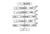
図19は、上記ステップS12におけるモード設定処理を示すフローチャートである。
【0069】
モード設定処理では、先ず、ステップS25でカップ洗浄処理のモードの設定が行われた後、順次、ステップS26〜ステップS29に移行されながらノズル洗浄処理、回転テーブル清掃処理、ピン洗浄処理及び処理テーブル清掃処理の各モード設定が行われる。
【0070】
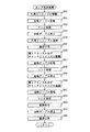
各ステップS25〜ステップS29での各モード設定は、図20に示すフローチャートに従って行われる。
【0071】
このフローでは、先ず、ステップS30でBUSY・ONモード(以下、BNモードという)が指定されたか否かが判断される。BNモードとは、BUSY・ONの検知(基板処理装置の稼働に応じたタイミング)に基づいて洗浄を行うモードである。このモードが指定されたと判断された場合には、さらにステップS31に移行されて簡易モードが指定されたか否かが判断され、簡易モードが指定された場合にはステップS32に移行されて洗浄モードがBN簡易モードに設定される。一方、簡易モードが指定されていないと判断された場合には、ステップS33に移行されて洗浄モードがBN通常モードに設定される。
【0072】
ここで、簡易モードとは、通常モードでの処理を簡略化して行うモードで、たとえば、通常モードに比して洗浄時間が短く設定される等のモードである。通常モード及び簡易モードの具体的な内容は各洗浄処理毎に異なっており、詳しくは後述する。
【0073】
ステップS30でBNモードが指定されていないと判断された場合には、ステップS34に移行され、ここでBUSY・ONインターバルモード(以下、BNインターバルモードという)が指定されたか否かが判断される。BNインターバルモードとは、BNインターバルの検知(基板処理装置の非処理状態の発生に応じたタイミング)に基づいて洗浄を行うモードであり、このモードが指定されたと判断された場合には、さらにステップS35に移行され、簡易モードが指定されたか否かが判断される。そして、簡易モードが指定された場合にはステップS36に移行されて洗浄モードがBNインターバル簡易モードに設定される。一方、簡易モードが指定されていない場合には、ステップS37に移行されて洗浄モードがBNインターバル通常モードに設定される。
【0074】
ステップS34でBNインターバルモードが指定されていないと判断された場合には、ステップS38に移行され、ここでロットモードが指定されたか否かが判断される。ロットモードとは、指定数のロットの終了の検知に基づいて洗浄を行うモードであり、このモードが指定されたと判断された場合には、さらにステップS39に移行され、簡易モードが指定されたか否かが判断される。そして、簡易モードが指定された場合にはステップS40に移行されて洗浄モードがロット簡易モードに設定される。一方、簡易モードが指定されていない場合には、ステップS41に移行されて洗浄モードがロット通常モードに設定される。なお、ロット数の指定は、例えばモード設定時にあわせて行われる。
【0075】
ステップS38でロットモードが指定されていないと判断された場合には、ステップS42に移行され、ここでBUSY・OFFモード(以下、BFモードという)が指定されたか否かが判断される。BFモードとは、BUSY・OFFの検知(基板処理装置の停止に応じたタイミング)に基づいて洗浄を行うモードであり、このモードが指定されたと判断された場合には、さらにステップS43に移行され、簡易モードが指定されたか否かが判断される。そして、簡易モードが指定された場合にはステップS44に移行されて洗浄モードがBF簡易モードに設定される。一方、簡易モードが指定されていない場合には、ステップS45に移行されて洗浄モードがBF通常モードに設定される。
【0076】
ステップS42でBFモードが指定されていないと判断された場合には、ステップS46に移行され、ここで遅延モードが指定されたか否かが判断される。遅延モードとは、コーターユニット14、あるいは端縁処理ユニット16への基板Wの到達遅れの検知(基板の搬入遅れ量に応じたタイミング)に基づいて洗浄を行うモードであり、このモードが指定されたと判断された場合には、さらにステップS47に移行され、簡易モードが指定されたか否かが判断される。そして、簡易モードが指定された場合にはステップS48に移行されて洗浄モードが遅延簡易モードに設定される。一方、簡易モードが指定されていない場合には、ステップS49に移行されて洗浄モードが遅延通常モードに設定される。
【0077】
なお、図20に示すフローチャートは、洗浄モードを上記各モードから択一的に設定する場合の例であり、例えば、図25及び図26に示すようなフローチャートに従って洗浄モードを設定することにより上記各モードを重複設定するようにしてもよい。このフローチャートについて簡単に説明すると、先ず、ステップS90においてBNモードが指定されたか否かが判断され、指定された場合には、ステップS95〜S97の処理を経てBN通常モード、あるいはBN簡易モードが設定されてステップS91に移行される。
【0078】
ステップS91では、BNインターバルモードが指定されたか否かが判断され、指定された場合には、ステップS98〜S100の処理を経てBNインターバル通常モード、あるいはBNインターバル簡易モードが設定されてステップS92に移行される。そして、以後同様にステップS92,S93,S94において順次ロットモード、BFモード及び遅延モードが指定されたか否かが判断され、指定された場合にはそれぞれ指定されたモードが設定される。
【0079】
図21〜図24は、図17及び図18に示すフローチャートのステップS14,ステップS16,ステップS18,ステップS20及びステップS10で実行される各洗浄処理を示している。以下、これらの処理について説明する。
【0080】
図21は、カップ洗浄処理を示している。この処理では、先ず、外周リンスノズル55が作動位置に移動させられ、その後、回転テーブル32が低速で回転させられながら外周リンスノズル55から一定時間リンスが噴射される。これによって回転テーブル32の周縁が洗浄される(ステップS50〜S52)。
【0081】
リンス噴射が停止されると、これに同期して回転テーブル32が停止され、外周リンスノズル55が退避位置に移動させられるとともに、蓋部31が下降端位置に移動させられて基板保持部30に合体させられる(ステップS53〜S55)。そして、第1PRノズル65及びチャックリンスノズル66が作動位置に移動させられた後、回転テーブル32が回転させられながら第1PRノズル65、チャックリンスノズル66及び第2PRノズル67から一定時間リンスが噴射される。これによってプレート51の上下面及び回転テーブル32の表面が洗浄される(ステップS56〜S58)。
【0082】
リンス噴射が停止されると、これに同期して回転テーブル32が停止され、第1PRノズル65及びチャックリンスノズル66が退避位置に移動させられる(ステップS59,S60)。そして、これら第1PRノズル65及びチャックリンスノズル66の移動が完了すると、再度、回転テーブル32が回転させられ、カップリンスノズル56,バックリンスノズル57,トラップリンスノズル58及び排気口リンスノズル59から一定時間リンスが噴射される。これによりカップ34の内周面、回転テーブル32の裏面、レジスト排出口61及び排気通路64内が洗浄される(ステップS61,S62)。
【0083】
そして、リンス噴射が停止されると、次いでステップS63で乾燥処理が行われる。この乾燥処理は、回転テーブル32が一定時間高速回転させられ、回転テーブル32に付着したリンスを遠心力で除去することにより行われる。
【0084】
乾燥処理が完了すると、回転テーブル32が停止させられ、その後、蓋部31が上昇端位置まで移動させられてカップ洗浄処理が終了する(ステップS63〜S65)。
【0085】
ところで、このようなカップ洗浄処理において図21に示すステップS50〜ステップS65の処理は、カップ洗浄の通常モードの処理であって、簡易モードの処理では、例えば、外周リンスノズル55,第2PRノズル67及び排気口リンスノズル59によるリンス噴射が省略された処理、すなわち上記フローにおけるステップS50〜S54が省略された処理が行われるようになっている。
【0086】
図22は、ノズル洗浄処理を示している。この処理では、先ず、液供給装置35において、溶剤ポット40が下降端位置に移動させれた後、支持部材37が移動させられてノズル38が洗浄位置にセットされる(ステップS70,S71)。そして、ノズル洗浄装置42において、洗浄ヘッド43が原点位置からノズル38に沿って所定回数だけ往復移動させられつつ、この移動中に洗浄ノズル47からリンス及びN2ブローが噴射されることによってノズル38の洗浄が行われる(ステップS72)。
【0087】
こうして洗浄ヘッド43が所定回数だけ往復移動させられ、洗浄ヘッド43が上記原点位置にリセットされると、支持部材37が移動させられてノズル38が退避位置にリセットされ、その後、溶剤ポット40が上昇端位置にリセットされることによりノズル洗浄処理が終了する(ステップS73,S74)。
【0088】
なお、ノズル洗浄処理における簡易モードは、上記ステップS72での洗浄ヘッド43の往復移動回数が通常モードよりも少なく設定されるようになっており、例えば、通常モードで洗浄ヘッド43を2往復させる場合、簡易モードでは洗浄ヘッド43を1往復だけ移動させるようになっている。
【0089】
図23は、ピン洗浄処理を示している。この処理では、ピン洗浄装置86において洗浄ポット87が上昇端位置にセットされ、これにより位置決め装置82の位置決めピン85が洗浄ポット87内に挿入させられる(ステップS80)。そして、位置決めピン85に対して一定時間だけリンスが噴射されて位置決めピン85の洗浄が行われた後、N2ブローが一定時間噴射されて位置決めピン85の乾燥処理が行われる(ステップS81,S82)。
【0090】
こうして乾燥処理が終了すると、上記洗浄ポット87が下降端位置にリセットされて位置決めピン85の洗浄処理が終了する(ステップS83)。
【0091】
なお、ピン洗浄処理における簡易モードは、上記ステップS81でのリンス噴射時間が通常モードよりも短く設定されるようになっており、例えば、簡易モードでは、リンス噴射時間が通常モードの半分の時間に設定されるようになっている。
【0092】
図24は、コーターユニット14の回転テーブル清掃処理を示している。この処理では、テーブルクリーナー75のヘッド76が回転テーブル32の吸着部33の一端側にセットされた後、吸着部33上で所定回数だけ往復移動させられ、この移動中に超音波発生器79a及びバキュームノズル79bが作動させられることにより回転テーブル32の清掃が行われる(ステップS85〜S87)。そして、ヘッド76が所定回数だけ往復移動させられると、ヘッド76がカップ34外部の初期位置にリセットされて回転テーブル32の清掃が終了する。
【0093】
回転テーブル清掃処理における簡易モードは、ヘッド76の往復移動回数が通常モードよりも少なく設定されるようになっており、例えば、通常モードで洗浄ヘッド76を2往復させる場合、簡易モードではヘッド76を1往復だけ移動させるようになっている。
【0094】
なお、端縁処理ユニット16のテーブルクリーナー90による処理テーブル清掃処理も、基本的にはこの図24に示すフローに従って行われるようになっており、ここではその説明を省略する。
【0095】
以上説明したように、上記基板処理装置10では、コーターユニット14及び端縁処理ユニット16に搭載される各洗浄装置をそれぞれBNモード等の複数のタイミングで作動させることができるようにしたため、各洗浄装置の洗浄タイミングをそれぞれ基板Wの処理状況、各洗浄装置の機能、あるいは洗浄箇所等に応じた適切なタイミングに設定することにより各洗浄装置によって効率良く、しかも適切に洗浄処理を行うことができる。従って、各種洗浄装置を一律に同じタイミングで作動させていた従来のこの種の装置に比べると、基板Wの処理効率を適切に確保しつつパーティクルの発生を確実に防止することができる。
【0096】
特に、上記実施形態では、このような各洗浄装置の作動タイミングのみならず、洗浄内容をも選択的に設定可能としている、すなわち、洗浄内容を通常モード及び簡易モードから選択的に設定できるようにしているため、作動タイミングとの兼ね合いでこれらのモードから適切なモードを選定することにより、各洗浄装置の機能、あるいは洗浄箇所等に応じて適切な洗浄処理を行うことができるとともに、基板Wの処理タクトに影響を与えない範囲で最大限の時間を有効に利用して洗浄処理を行うことができる。従って、これによっても処理効率の確保とパーティクルの発生防止がより良く達成される。
【0097】
なお、上記実施形態の基板処理装置10は、本発明が適用された基板処理装置の一例であって、その具体的な構成は本発明の要旨を逸脱しない範囲で適宜変更可能である。
【0098】
例えば、上記実施形態では特に説明していないが、上記ベークユニット18では基板Wをプレート上に保持した状態で処理を施すことが行われるため、このプレートを洗浄する装置として、例えば上記テーブルクリーナー75,90のような洗浄装置を設けることが考えられる。そのため、この場合には、これらのプレートに対する洗浄装置を上記実施形態の各タイミングで作動させるようにして、図17,図18に示す制御フローに従って制御するようにしてもよい。
【0099】
また、上記基板処理装置10では、コーターユニット14がスピンコーターから構成されているが、勿論、スリットコーター、あるいはロールコーターといった薄膜形成のための装置からコーターユニット14を構成する場合にも本願発明を適用することができる。
【0100】
さらに、上記実施形態では、各洗浄装置を作動させるタイミングとして、BNモード、BNインターバルモード、ロットモード、BFモード及び遅延モードといった5種類のモードからタイミングモードを設定するようにしているが、勿論、これ以外のタイミングモードを設定できるようにしてもよい。例えば、コーターユニット14より上流側に多くの処理ユニットが配設される場合には、1ロットの処理が終了して次のロットの1枚目の基板がコーターユニット14より上流側の予め設定された処理ユニットに搬入されるタイミング、あるいはその処理ユニットでの上記1枚目の基板の処理完了のタイミングで洗浄処理を行うようにする等、上流側の処理ユニットにおける基板の処理状況に応じたタイミングで洗浄処理を行うタイミングモードを設定可能としたり、あるいは基板1枚毎に洗浄処理を行うタイミングモードを設定可能にするようにしてもよい。つまり、タイミングモードは、適用される基板処理装置の具体的な構成に応じて適宜定めるようにすればよい。また、上記実施形態では、洗浄処理を通常モード及び簡易モードから選定可能としているが、例えば、これらのモードに加えて、洗浄をより精密に行う精密モードを選定可能としたり、あるいは、より多段階(例えば、10段階)に洗浄内容を選定できるようにしてもよい。勿論、洗浄条件をモード選定できるようにする必要は必ずしもなく、例えば、単一の条件で洗浄処理を行うようにしても構わない。
【0101】
【発明の効果】
以上説明したように、本発明の基板処理装置は、複数の処理部に基板を搬出入しながら処理を施すことにより基板表面に薄膜を形成するとともに、処理により装置へ付着した不要な付着物を洗浄除去する複数の洗浄手段を備えた基板処理装置において、各洗浄手段の作動タイミングを基板の処理状況、各洗浄手段の機能、あるいは洗浄箇所等に応じた適切なタイミングで作動させることが可能となり、特に、作動タイミングとして、当該洗浄手段が備えられる処理部より上流側の処理部における基板の処理状況に応じたタイミング、又は基板処理装置の稼働中であって、当該洗浄手段が備えられる処理部への基板の搬入遅れ量に応じたタイミングが設定されるので、基板の処理効率を適切に確保しつつパーティクルの発生を確実に防止することができる。
【0102】
この装置において、上記作動タイミングとして、(1)当該洗浄手段が備えられる処理部より上流側の処理部における基板の処理状況に応じたタイミング、(2)基板処理装置の稼働中であって、当該洗浄手段が備えられる処理部への基板の搬入遅れ量に応じたタイミング、(3)基板処理装置の稼働時及び停止時の少なくとも一方に応じたタイミング、(4)基板処理装置の稼働中であって非処理状態の発生に応じたタイミングのうち少なくとも(1)のタイミングを含む複数のタイミングを設定可能にする、あるいは少なくとも(2)のタイミングを含む複数のタイミングを設定可能にすれば、各洗浄手段を基板の処理状況や各洗浄手段の機能等に適したより良いタイミングで作動させることができるとともに、そのようなタイミング設定を容易に行うことが可能となる。
【0103】
さらに、洗浄手段を複数の動作条件から選択的に作動させるように上記洗浄制御手段を構成するようにすれば、各洗浄手段の機能、あるいは洗浄箇所等に応じて洗浄処理を行うことができるとともに、基板の処理タクトに影響を与えない範囲で最大限の時間を有効に利用して洗浄を行うことができる。
【0104】
特に、処理部として、回転テーブル上に保持される基板の表面にノズル部材を介して液体を供給して基板の回転に伴う遠心力により基板表面に薄膜を形成する薄膜形成部を有し、上記洗浄手段として、上記ノズル部材を洗浄するノズル洗浄手段と、回転テーブルを洗浄する回転テーブル洗浄手段と、回転テーブル周辺を洗浄する周辺洗浄手段とを有する基板処理装置や、あるいは、処理部として、搬送手段により処理テーブル上に移載される薄膜形成後の基板を位置決め部材により位置決めして基板端縁に形成された不要な薄膜を除去する端縁除去部を有し、上記洗浄手段として、上記位置決め部材を洗浄する位置決め部材洗浄手段と、上記処理テーブルを洗浄する処理テーブル洗浄手段とを有する基板処理装置においては、薄膜形成のための液体が頻繁に装置に付着するため、このような基板処理装置について上記構成を採用するようにすれば、基板の処理効率の確保及びパーティクル発生の防止を通じて基板の生産性向上及び品質向上が達成できる。
【図面の簡単な説明】
【図1】 本発明が適用される基板処理装置を示す平面略図である。
【図2】 上記基板処理装置のコーターユニット及び端縁処理ユニットを示す平面図である。
【図3】 上記コーターユニットに適用されているスピンコーターを示す斜視図である。
【図4】 液供給装置を示す平面図である。
【図5】 液供給装置及び溶剤ポットを示す側面図である。
【図6】 液供給装置及びノズル洗浄装置を示す側面図である。
【図7】 ノズル洗浄装置の洗浄ヘッドを示す断面図である。
【図8】 ノズル洗浄装置の洗浄ヘッドを示す平面図である。
【図9】 スピンコーターの基板保持部を示す要部断面図である。
【図10】 スピンコーターの蓋部を示す要部断面図である。
【図11】 第1プレートリンスノズル及びチャックリンスノズルの駆動構造を示す平面図である。
【図12】 テーブルクリーナーのヘッドの構成を示す断面図である。
【図13】 (a)〜(c)はコーターユニットに設けられたテーブルクリーナーによる洗浄動作を説明する概略図である。
【図14】 位置決め装置による基板の位置決め状態を示す側面図である。
【図15】 (a),(b)はピン洗浄装置によるピン洗浄動作を説明する図である。
【図16】 コーターユニット及び端縁処理ユニットの各洗浄装置を制御する基板処理装置の制御系を示すブロック図である。
【図17】 コーターユニット及び端縁処理ユニットの各洗浄装置の制御例を示すフローチャート(メインフロー)である。
【図18】 コーターユニット及び端縁処理ユニットの各洗浄装置の制御例を示すフローチャート(メインフロー)である。
【図19】 図17,図18のフローチャートにおけるモード設定処理を示すフローチャートである。
【図20】 図19のフローチャートにおける各洗浄処理モード設定処理を示すフローチャートである。
【図21】 カップ洗浄処理を示すフローチャートである。
【図22】 ノズル洗浄処理を示すフローチャートである。
【図23】 ピン洗浄処理を示すフローチャートである。
【図24】 回転テーブル洗浄処理を示すフローチャートである。
【図25】 図19のフローチャートにおける各洗浄処理モード設定処理の他の例を示すフローチャートである。
【図26】 図19のフローチャートにおける各洗浄処理モード設定処理の他の例を示すフローチャートである。
【符号の説明】
10 基板処理装置
12 待機ユニット
14 コーターユニット
16 端縁処理ユニット
18 ベークユニット
20,21,22 搬送ロボット
30 基板保持部
31 蓋部
35 液供給装置
42 ノズル洗浄装置
55 外周リンスノズル
56 カップリンスノズル
57 バックリンスノズル
58 トラップリンスノズル
59 排気口リンスノズル
65 第1プレートリンスノズル
66 チャックリンスノズル
67 第2プレートリンスノズル
75,90 テーブルクリーナー
80 処理テーブル
82 位置決め装置
86 ピン洗浄装置
100 本体制御部
101 コーターユニット制御部
111 端縁処理ユニット制御部[0001]
BACKGROUND OF THE INVENTION
The present invention relates to a substrate processing apparatus and a cleaning method applied to manufacture of various substrates such as a semiconductor wafer and a glass substrate of a liquid crystal display.
[0002]
[Prior art]
Conventionally, as an apparatus for manufacturing a semiconductor wafer, a glass substrate of a liquid crystal display, etc., for example, a substrate cleaning unit for cleaning a substrate before processing, and a coater unit such as a spin coater for forming a thin film of a photoresist solution on the substrate; An edge processing unit that removes unnecessary thin film on the substrate edge of the thin film formed by the spin coater, a baking unit that dries the photoresist liquid on the substrate surface from which the unnecessary thin film on the edge is removed, and the like There is generally known a substrate processing apparatus that performs processing while transferring a substrate between units by a transfer robot.
[0003]
In such a substrate processing apparatus, in the coater unit and the edge processing unit, the photoresist liquid adheres to each part of the apparatus such as a nozzle for supplying the photoresist liquid during the processing process, and this causes drying to cause particle generation. For this reason, a cleaning device for injecting a cleaning liquid to a portion where the photoresist liquid adheres is provided, and thereby the photoresist liquid is cleaned and removed.
[0004]
[Problems to be solved by the invention]
However, in the conventional substrate processing apparatus, the above-described cleaning apparatus is generally operated for every predetermined number of substrates set in advance. For example, the transfer of the substrate is interrupted or stopped for some reason. Then, since the cleaning apparatus does not operate for a long period of time, the attached photoresist solution is dried and particles are generated, or removal of the attached resist solution is extremely difficult.
[0005]
In addition, when a plurality of cleaning devices are provided, the amount of photoresist solution attached and the time required to remove the attached photoresist solution depend on the portion to which the photoresist solution adheres, the cleaning ability of each cleaning device, etc. Because of the large difference, it is not always sufficient to operate various cleaning apparatuses uniformly under the same conditions in order to effectively prevent the generation of particles and to ensure the processing efficiency of the substrate.
[0006]
The present invention has been made to solve the above problems, and by operating the cleaning device at an appropriate timing according to the processing status of the substrate, the generation of particles is ensured while ensuring the processing efficiency of the substrate. It is an object of the present invention to provide a substrate processing apparatus and a cleaning method that can be prevented.
[0007]
[Means for Solving the Problems]
The substrate processing apparatus of the present invention forms a thin film on the substrate surface by carrying out processing while carrying the substrate in and out of a plurality of processing units, and also performs a plurality of cleanings for cleaning and removing unnecessary deposits attached to the apparatus by the processing. In the substrate processing apparatus provided with the means, timing setting means for enabling the operation timing of each of the cleaning means to be set, and cleaning control means for operating each of the cleaning means at the operation timing set by the timing setting means, Equipped withThe operation timing is set to a timing according to the processing status of the substrate in the processing section upstream of the processing section provided with the cleaning means.(Claim 1).
[0008]
In addition, the substrate processing is provided with a plurality of cleaning means for forming a thin film on the substrate surface by carrying out processing while carrying the substrate in and out of a plurality of processing units, and cleaning and removing unnecessary deposits attached to the apparatus by the processing. The apparatus comprises a timing setting means for enabling the operation timing of each of the cleaning means to be set, and a cleaning control means for operating each of the cleaning means at an operation timing set by the timing setting means. The timing is set to a timing corresponding to the amount of delay in loading the substrate into the processing section provided with the cleaning means while the substrate processing apparatus is in operation (Claim 2).
[0009]
ThisTheseAccording to the apparatus, the operation timing of each cleaning means can be operated at an appropriate timing according to the processing status of the substrate, the function of each cleaning means, or the cleaning location,In particular, each of the above timings should be set as the operation timingThis makes it possible to effectively prevent the generation of particles while ensuring the processing efficiency of the substrate.
[0010]
ThisTheseIn the equipment ofThe timing setting means includes, as the operation timing, (1) a timing according to the processing status of the substrate in the processing section upstream of the processing section provided with the cleaning means, and (2) the operation of the substrate processing apparatus. , Timing according to the amount of delay in loading the substrate into the processing unit provided with the cleaning means, (3) timing according to at least one of when the substrate processing apparatus is operated and when stopped, and (4) during operation of the substrate processing apparatus Of the timings corresponding to the occurrence of the non-processing state, a plurality of timings including at least (1) timing can be set (Claim 3), or a plurality of timings including at least (2) timing. It is preferable that the timing can be set.
[0011]
According to these apparatuses, each cleaning unit can be operated at a better timing suitable for the processing status of the substrate, the function of each cleaning unit, and the like, and such timing setting can be easily performed.
[0012]
Claim 3And claim 4In the description, “when operating and when stopped” is not limited to when the power is turned on / off, and all substrates are processed after the substrates are loaded into the substrate processing apparatus, and the substrates are unloaded from the substrate processing apparatus. It is meant to include after.
[0013]
Further, if the cleaning control means is configured to selectively operate the cleaning means from a plurality of operating conditions (claims)5) In addition, the cleaning process can be performed according to the function of each cleaning means, the cleaning location, etc., and the maximum time can be effectively used as long as it does not affect the processing tact of the substrate. It becomes possible.
[0014]
In particular, the processing unit includes a thin film forming unit that supplies a liquid to the surface of the substrate held on the rotary table via a nozzle member and forms a thin film on the substrate surface by a centrifugal force accompanying the rotation of the substrate. As a cleaning means, a substrate processing apparatus having a nozzle cleaning means for cleaning the nozzle member, a rotary table cleaning means for cleaning the rotary table, and a peripheral portion cleaning means for cleaning the periphery of the rotary table (claims)6Alternatively, the processing unit has an edge removing unit that positions the substrate after the thin film is transferred by the conveying means on the processing table by the positioning member and removes unnecessary thin film formed on the substrate edge. In the substrate processing apparatus having the positioning member cleaning means for cleaning the positioning member and the processing table cleaning means for cleaning the processing table as the cleaning means (claim 7), the liquid for forming the thin film is Such a substrate processing apparatus, as it frequently adheres to the apparatus, is defined in the above claims.5By adopting this configuration, it becomes possible to improve the productivity and quality of the substrate through ensuring the processing efficiency of the substrate and preventing the generation of particles.
[0015]
As a more specific configuration,The substrate processing apparatus includes a table that holds a substrate and a nozzle member that supplies a liquid to the surface of the substrate held on the table.As a cleaning meansNozzle cleaning hand for cleaning the nozzle memberStepIt has(Claim 8).
[0016]
On the other hand, the cleaning method according to the present invention forms a thin film on the surface of the substrate by carrying out the processing while carrying the substrate in and out of a plurality of processing units, and also cleans and removes unnecessary deposits attached to the apparatus by the processing. A cleaning method for the processing section of the substrate processing apparatus provided with the cleaning means, wherein operation timings of the cleaning means are respectively set.According to the processing status of the substrate in the processing unit upstream of the processing unit provided with the cleaning meansThe timing is set in advance, and each of the processing units is cleaned by operating each of the cleaning means at this operation timing (claims).9).
[0017]
Another cleaning method according to the present invention is as follows.A substrate processing apparatus provided with a plurality of cleaning means for forming a thin film on a substrate surface by carrying out processing while carrying the substrate in and out of a plurality of processing units, and cleaning and removing unnecessary deposits attached to the apparatus by the processing. In the cleaning method for the processing unit, the operation timing of each cleaning unit is set to a timing corresponding to the amount of delay in loading the substrate into the processing unit in which the substrate processing apparatus is in operation. Each processing unit is set by operating each cleaning means at this operation timing.Is to be washed (claims)10).
[0018]
In addition, in the description of each claim, “cleaning” includes not only so-called cleaning in which dirt is washed away using pure water or a cleaning agent, but also so-called cleaning that sweeps or sucks off adhering foreign matter. It is.
[0019]
DETAILED DESCRIPTION OF THE INVENTION
Embodiments of the present invention will be described with reference to the drawings.
[0020]
FIG. 1 schematically shows an example of a substrate processing apparatus to which the present invention is applied. As shown in the figure, a
[0021]
The
[0022]
The
[0023]
The rotary table 32 is rotationally driven by a
[0024]
The
[0025]
At the time of processing, the
[0026]
On the other hand, when the liquid is not supplied, the
[0027]
As shown in FIGS. 4 and 5, a
[0028]
A
[0029]
As shown in FIGS. 7 and 8, the cleaning
[0030]
As shown in FIG. 3, the
[0031]
By the way, the
[0032]
Specifically, as shown in FIGS. 3 and 9, the
[0033]
The outer peripheral rinsing
[0034]
The cup rinse
[0035]
The back rinse
[0036]
The trap rinse
[0037]
The exhaust port rinse
[0038]
As shown in FIG. 10, the
[0039]
Here, as shown in FIGS. 10 and 11, the
[0040]
The
[0041]
In addition, each nozzle 55-59 of the said board | substrate holding |
[0042]
The
[0043]
The
[0044]
At the time of cleaning, after the
[0045]
On the other hand, as shown in FIG. 2, the
[0046]
The processing table 80 can be moved up and down by driving an air cylinder or the like. When the substrate W is carried in, the processing table 80 receives the substrate W transported by the
[0047]
Each of the
[0048]
The
[0049]
Each
[0050]
As shown in FIGS. 2 and 15A, the
[0051]
At the time of cleaning, the cleaning
[0052]
As shown in FIG. 2, the
[0053]
In the
[0054]
During the processing operation on the substrate W, various cleanings such as the
[0055]
FIG. 16 shows a control system of the
[0056]
As shown in the figure, the
[0057]
The coater
[0058]
Similarly, the edge processing
[0059]
[0060]
Next, control of the apparatuses for cleaning in the
[0061]
In this flow, first, initial setting is performed in step S1, where each cleaning mode of nozzle cleaning of the
[0062]
In step S <b> 2, it is determined whether or not a mode setting command has been issued from the main
[0063]
In step S3, it is determined whether or not a drive start command has been issued. If no start command has been issued, a standby state is set. On the other hand, if a start command is issued, it is determined in step S4 whether the
[0064]
If it is determined in step S8 that it is not BUSY · OFF, the process proceeds to step S4. On the other hand, if it is determined in step S8 that it is BUSY · OFF, the
[0065]
If it is determined in step S2 of the flowchart that the mode setting command has been issued, the process proceeds to step S12, and the nozzle cleaning, cup cleaning, rotary table cleaning and edge processing unit of the
[0066]
If it is determined in step S4 that BUSY / ON, the process proceeds to step S13, and it is determined whether or not there is a cleaning process set in the later-described BUSY / ON mode among the above-described cleaning processes. If there is a cleaning process, the process proceeds to step S14 and the cleaning process is executed.
[0067]
Similarly, if the BUSY / ON interval is determined in step S5, it is determined in step S15 whether there is a cleaning process set in a BUSY / ON interval mode, which will be described later, and a carry-in delay occurs in step S6. If it is determined in step S17, it is determined whether or not there is a cleaning process set in a later-described delay mode. If it is determined in step S7 that the lot has been completed, the lot mode described later is set in step S19. When it is determined in step S8 that BUSY / OFF is present, it is determined in step S9 whether there is a cleaning process set in a BUSY / OFF mode, which will be described later. . If there is a cleaning process set for each mode in these determinations, the process proceeds to steps S16, S18, S20 and S10, respectively, and the cleaning process is executed.
[0068]
FIG. 19 is a flowchart showing the mode setting process in step S12.
[0069]
In the mode setting process, first, after setting the mode of the cup cleaning process in step S25, the nozzle cleaning process, the rotary table cleaning process, the pin cleaning process, and the process table cleaning are sequentially performed while the process proceeds to step S26 to step S29. Each mode of processing is set.
[0070]
Each mode setting in steps S25 to S29 is performed according to the flowchart shown in FIG.
[0071]
In this flow, first, in step S30, it is determined whether or not the BUSY / ON mode (hereinafter referred to as BN mode) is designated. The BN mode is a mode in which cleaning is performed based on BUSY / ON detection (timing according to operation of the substrate processing apparatus). If it is determined that this mode has been designated, the process further proceeds to step S31 to determine whether or not the simple mode has been designated. If the simple mode has been designated, the process proceeds to step S32 and the cleaning mode is set. The BN simple mode is set. On the other hand, if it is determined that the simple mode is not designated, the process proceeds to step S33 and the cleaning mode is set to the BN normal mode.
[0072]
Here, the simple mode is a mode in which processing in the normal mode is simplified, and is a mode in which, for example, the cleaning time is set shorter than that in the normal mode. The specific contents of the normal mode and the simple mode differ for each cleaning process, and will be described in detail later.
[0073]
If it is determined in step S30 that the BN mode is not designated, the process proceeds to step S34, where it is determined whether or not the BUSY / ON interval mode (hereinafter referred to as BN interval mode) is designated. The BN interval mode is a mode in which cleaning is performed based on detection of the BN interval (timing according to occurrence of a non-processing state of the substrate processing apparatus). If it is determined that this mode is designated, a step is further performed. The process proceeds to S35 and it is determined whether or not the simple mode is designated. When the simple mode is designated, the process proceeds to step S36, and the cleaning mode is set to the BN interval simple mode. On the other hand, when the simple mode is not designated, the process proceeds to step S37 and the cleaning mode is set to the BN interval normal mode.
[0074]
If it is determined in step S34 that the BN interval mode is not specified, the process proceeds to step S38, where it is determined whether or not the lot mode is specified. The lot mode is a mode in which cleaning is performed based on detection of the end of a specified number of lots. If it is determined that this mode has been specified, the process further proceeds to step S39 to determine whether the simple mode has been specified. Is judged. When the simple mode is designated, the process proceeds to step S40 and the cleaning mode is set to the lot simple mode. On the other hand, if the simple mode is not designated, the process proceeds to step S41 and the cleaning mode is set to the lot normal mode. The number of lots is specified at the time of mode setting, for example.
[0075]
If it is determined in step S38 that the lot mode is not specified, the process proceeds to step S42, where it is determined whether the BUSY / OFF mode (hereinafter referred to as BF mode) is specified. The BF mode is a mode in which cleaning is performed based on BUSY / OFF detection (timing according to stoppage of the substrate processing apparatus). If it is determined that this mode is designated, the process proceeds to step S43. Then, it is determined whether or not the simple mode is designated. When the simple mode is designated, the process proceeds to step S44 and the cleaning mode is set to the BF simple mode. On the other hand, if the simple mode is not designated, the process proceeds to step S45 and the cleaning mode is set to the BF normal mode.
[0076]
If it is determined in step S42 that the BF mode is not specified, the process proceeds to step S46, where it is determined whether or not the delay mode is specified. The delay mode is a mode in which cleaning is performed based on detection of arrival delay of the substrate W to the
[0077]
Note that the flowchart shown in FIG. 20 is an example in which the cleaning mode is set alternatively from the above modes. For example, by setting the cleaning mode according to the flowcharts shown in FIGS. The mode may be set to overlap. Briefly explaining this flowchart, first, it is determined whether or not the BN mode is designated in step S90, and if designated, the BN normal mode or the BN simple mode is set through the processing of steps S95 to S97. Then, the process proceeds to step S91.
[0078]
In step S91, it is determined whether or not the BN interval mode is designated. If designated, the BN interval normal mode or the BN interval simple mode is set through the processing of steps S98 to S100, and the process proceeds to step S92. Is done. Thereafter, similarly, in steps S92, S93, and S94, it is determined whether or not the lot mode, the BF mode, and the delay mode are sequentially designated. If designated, the designated modes are set.
[0079]
FIGS. 21 to 24 show the respective cleaning processes executed in step S14, step S16, step S18, step S20 and step S10 of the flowcharts shown in FIGS. Hereinafter, these processes will be described.
[0080]
FIG. 21 shows the cup cleaning process. In this process, first, the outer peripheral rinsing
[0081]
When the rinsing injection is stopped, the rotary table 32 is stopped in synchronism with this, the outer peripheral rinsing
[0082]
When the rinsing injection is stopped, the rotary table 32 is stopped in synchronization with this, and the
[0083]
And if rinse injection is stopped, a drying process will be performed at Step S63 next. This drying process is performed by rotating the rotary table 32 at a high speed for a certain period of time and removing the rinse adhering to the rotary table 32 by centrifugal force.
[0084]
When the drying process is completed, the rotary table 32 is stopped, and then the
[0085]
Incidentally, in such a cup cleaning process, the processes of steps S50 to S65 shown in FIG. 21 are processes in the normal mode of the cup cleaning, and in the simple mode process, for example, the outer peripheral rinse
[0086]
FIG. 22 shows the nozzle cleaning process. In this process, first, in the
[0087]
Thus, when the cleaning
[0088]
The simple mode in the nozzle cleaning process is set such that the number of reciprocating movements of the cleaning
[0089]
FIG. 23 shows the pin cleaning process. In this process, the cleaning
[0090]
When the drying process is thus completed, the cleaning
[0091]
In the simple mode in the pin cleaning process, the rinse injection time in step S81 is set to be shorter than that in the normal mode. For example, in the simple mode, the rinse injection time is half of the normal mode. It is set up.
[0092]
FIG. 24 shows the rotary table cleaning process of the
[0093]
The simple mode in the rotary table cleaning process is set such that the number of reciprocating movements of the
[0094]
Note that the processing table cleaning processing by the
[0095]
As described above, in the
[0096]
In particular, in the above embodiment, not only the operation timing of each cleaning device but also the cleaning content can be selectively set, that is, the cleaning content can be selectively set from the normal mode and the simple mode. Therefore, by selecting an appropriate mode from these modes in consideration of the operation timing, it is possible to perform an appropriate cleaning process according to the function of each cleaning device, the cleaning location, etc. The cleaning process can be performed by effectively using the maximum time within a range that does not affect the processing tact. Therefore, the processing efficiency can be ensured and the generation of particles can be better achieved.
[0097]
In addition, the
[0098]
For example, although not specifically described in the above embodiment, the
[0099]
In the
[0100]
Furthermore, in the above embodiment, the timing mode is set from five types of modes such as the BN mode, the BN interval mode, the lot mode, the BF mode, and the delay mode as the timing for operating each cleaning device. Other timing modes may be set. For example, when many processing units are arranged on the upstream side of the
[0101]
【The invention's effect】
As described above, the substrate processing apparatus of the present invention forms a thin film on the surface of the substrate by carrying out processing while carrying the substrate in and out of a plurality of processing units, and removes unnecessary deposits attached to the apparatus by processing. In a substrate processing apparatus provided with a plurality of cleaning means for cleaning and removing,The operation timing of each cleaning means can be operated at an appropriate timing according to the processing status of the substrate, the function of each cleaning means, the cleaning location, etc. In particular, the processing unit provided with the cleaning means as the operation timing The timing according to the processing status of the substrate in the processing section on the upstream side, or the timing according to the delay in loading of the substrate into the processing section provided with the cleaning means is set during the operation of the substrate processing apparatus. SoGeneration of particles can be reliably prevented while appropriately ensuring the substrate processing efficiency.
[0102]
In this device,As the operation timing, (1) timing according to the processing status of the substrate in the processing unit upstream of the processing unit provided with the cleaning unit, and (2) the substrate processing apparatus is in operation and provided with the cleaning unit. (3) Timing according to at least one of when the substrate processing apparatus is in operation and when it is stopped, and (4) When the substrate processing apparatus is in operation and in a non-processed state. If it is possible to set a plurality of timings including at least the timing (1) among the timings corresponding to the occurrence of the occurrence, or a plurality of timings including at least the timing (2) can be set, each cleaning means can be mounted on It can be operated at a better timing suitable for the processing conditions and functions of each cleaning means, and such timing setting is easily performed. It can become.
[0103]
Furthermore, if the cleaning control unit is configured to selectively operate the cleaning unit from a plurality of operating conditions, the cleaning process can be performed according to the function of each cleaning unit, the cleaning location, or the like. The cleaning can be performed by effectively using the maximum time within a range that does not affect the processing tact of the substrate.
[0104]
In particular, the processing unit includes a thin film forming unit that supplies a liquid to the surface of the substrate held on the rotary table via a nozzle member and forms a thin film on the substrate surface by a centrifugal force accompanying the rotation of the substrate. As a cleaning means, a substrate processing apparatus having a nozzle cleaning means for cleaning the nozzle member, a rotary table cleaning means for cleaning the rotary table, and a peripheral cleaning means for cleaning the periphery of the rotary table, or transported as a processing section A substrate having a thin film formed thereon, which is transferred onto the processing table, is positioned by a positioning member to remove an unnecessary thin film formed on the substrate edge, and the positioning unit serves as the positioning unit. In a substrate processing apparatus having a positioning member cleaning means for cleaning a member and a processing table cleaning means for cleaning the processing table, a thin film is formed. Since the liquid adheres to frequent device, on this substrate processing apparatusStructureBy adopting the configuration, it is possible to improve the productivity and quality of the substrate through ensuring the processing efficiency of the substrate and preventing the generation of particles.
[Brief description of the drawings]
FIG. 1 is a schematic plan view showing a substrate processing apparatus to which the present invention is applied.
FIG. 2 is a plan view showing a coater unit and an edge processing unit of the substrate processing apparatus.
FIG. 3 is a perspective view showing a spin coater applied to the coater unit.
FIG. 4 is a plan view showing a liquid supply apparatus.
FIG. 5 is a side view showing a liquid supply device and a solvent pot.
FIG. 6 is a side view showing a liquid supply device and a nozzle cleaning device.
FIG. 7 is a cross-sectional view showing a cleaning head of a nozzle cleaning device.
FIG. 8 is a plan view showing a cleaning head of the nozzle cleaning device.
FIG. 9 is a cross-sectional view of a principal part showing a substrate holding part of a spin coater.
FIG. 10 is a cross-sectional view of a main part showing a lid part of a spin coater.
FIG. 11 is a plan view showing a driving structure of a first plate rinse nozzle and a chuck rinse nozzle.
FIG. 12 is a cross-sectional view showing a configuration of a head of the table cleaner.
FIGS. 13A to 13C are schematic views for explaining a cleaning operation by a table cleaner provided in the coater unit.
FIG. 14 is a side view showing a positioning state of the substrate by the positioning device.
FIGS. 15A and 15B are diagrams for explaining a pin cleaning operation by a pin cleaning device. FIGS.
FIG. 16 is a block diagram showing a control system of a substrate processing apparatus that controls each cleaning device of a coater unit and an edge processing unit.
FIG. 17 is a flowchart (main flow) showing a control example of each cleaning device of the coater unit and the edge processing unit.
FIG. 18 is a flowchart (main flow) showing a control example of each cleaning device of the coater unit and the edge processing unit.
FIG. 19 is a flowchart showing a mode setting process in the flowcharts of FIGS. 17 and 18;
20 is a flowchart showing each cleaning process mode setting process in the flowchart of FIG.
FIG. 21 is a flowchart showing a cup cleaning process.
FIG. 22 is a flowchart showing a nozzle cleaning process.
FIG. 23 is a flowchart showing a pin cleaning process.
FIG. 24 is a flowchart showing a rotary table cleaning process.
FIG. 25 is a flowchart showing another example of each cleaning process mode setting process in the flowchart of FIG.
FIG. 26 is a flowchart showing another example of each cleaning process mode setting process in the flowchart of FIG.
[Explanation of symbols]
10 Substrate processing equipment
12 Standby unit
14 Coater unit
16 Edge processing unit
18 bake units
20, 21, 22 Transport robot
30 Substrate holder
31 Lid
35 Liquid supply device
42 Nozzle cleaning device
55 Peripheral rinse nozzle
56 Cup rinse nozzle
57 Back rinse nozzle
58 Trap rinse nozzle
59 Exhaust outlet rinse nozzle
65 First plate rinse nozzle
66 Chuck rinse nozzle
67 Second plate rinse nozzle
75,90 Table cleaner
80 processing table
82 Positioning device
86 pin cleaning equipment
100 Control unit
101 Coater unit controller
111 Edge processing unit controller
Claims (10)
(1)当該洗浄手段が備えられる処理部より上流側の処理部における基板の処理状況に応じたタイミング、
(2)基板処理装置の稼働中であって、当該洗浄手段が備えられる処理部への基板の搬入遅れ量に応じたタイミング、
(3)基板処理装置の稼働時及び停止時の少なくとも一方に応じたタイミング、
(4)基板処理装置の稼働中であって非処理状態の発生に応じたタイミングのうち少なくとも(1)のタイミングを含む複数のタイミングを設定可能にされていることを特徴とする請求項1記載の基板処理装置。 The timing setting means, as the operation timing,
( 1) Timing according to the processing status of the substrate in the processing unit upstream of the processing unit provided with the cleaning means,
(2) Timing in accordance with the amount of delay in loading the substrate into the processing unit provided with the cleaning means, while the substrate processing apparatus is in operation.
(3) Timing according to at least one of operation and stop of the substrate processing apparatus,
(4) The plurality of timings including at least the timing (1) among the timings corresponding to the occurrence of the non-processing state while the substrate processing apparatus is in operation can be set. Substrate processing equipment.
(1)当該洗浄手段が備えられる処理部より上流側の処理部における基板の処理状況に応じたタイミング、
(2)基板処理装置の稼働中であって、当該洗浄手段が備えられる処理部への基板の搬入遅れ量に応じたタイミング、
(3)基板処理装置の稼働時及び停止時の少なくとも一方に応じたタイミング、
(4)基板処理装置の稼働中であって非処理状態の発生に応じたタイミングのうち少なくとも(2)のタイミングを含む複数のタイミングを設定可能にされていることを特徴とする請求項2記載の基板処理装置。 The timing setting means, as the operation timing,
( 1) Timing according to the processing status of the substrate in the processing unit upstream of the processing unit provided with the cleaning means,
(2) Timing in accordance with the amount of delay in loading the substrate into the processing unit provided with the cleaning means, while the substrate processing apparatus is in operation.
(3) Timing according to at least one of operation and stop of the substrate processing apparatus,
(4) according to claim 2, characterized in that it is possible to set a plurality of timing including the timing of at least (2) of the timing corresponding to the occurrence of non-treated state even during the operating the substrate processing apparatus Substrate processing equipment.
前記各洗浄手段の作動タイミングをそれぞれ洗浄手段が備えられる処理部より上流側の処理部における基板の処理状況に応じたタイミングに予め設定しておき、この作動タイミングで各洗浄手段をそれぞれ作動させることにより前記各処理部を洗浄するようにしたことを特徴とする洗浄方法。A substrate processing apparatus provided with a plurality of cleaning means for forming a thin film on a substrate surface by carrying out processing while carrying the substrate in and out of a plurality of processing units, and cleaning and removing unnecessary deposits attached to the apparatus by the processing. A method of cleaning the processing unit,
The operation timing of each of the cleaning means is set in advance to a timing according to the processing status of the substrate in the processing section upstream of the processing section provided with the cleaning means, and each cleaning means is operated at this operation timing. The cleaning method is characterized in that each of the processing units is cleaned.
前記各洗浄手段の作動タイミングをそれぞれ基板処理装置の稼働中であって、当該洗浄手段が備えられる処理部への基板の搬入遅れ量に応じたタイミングに予め設定しておき、この作動タイミングで各洗浄手段をそれぞれ作動させることにより前記各処理部を洗浄するようにしたことを特徴とする洗浄方法。 The operation timing of each of the cleaning means is set in advance to a timing corresponding to the amount of delay in loading the substrate into the processing unit provided with the cleaning means while the substrate processing apparatus is in operation. A cleaning method, wherein each processing section is cleaned by operating each of the cleaning means.
Priority Applications (1)
| Application Number | Priority Date | Filing Date | Title |
|---|---|---|---|
| JP17634896A JP3673329B2 (en) | 1996-07-05 | 1996-07-05 | Substrate processing apparatus and cleaning method |
Applications Claiming Priority (1)
| Application Number | Priority Date | Filing Date | Title |
|---|---|---|---|
| JP17634896A JP3673329B2 (en) | 1996-07-05 | 1996-07-05 | Substrate processing apparatus and cleaning method |
Related Child Applications (1)
| Application Number | Title | Priority Date | Filing Date |
|---|---|---|---|
| JP2004365354A Division JP4006003B2 (en) | 2004-12-17 | 2004-12-17 | Substrate processing apparatus and cleaning method |
Publications (2)
| Publication Number | Publication Date |
|---|---|
| JPH1022204A JPH1022204A (en) | 1998-01-23 |
| JP3673329B2 true JP3673329B2 (en) | 2005-07-20 |
Family
ID=16012036
Family Applications (1)
| Application Number | Title | Priority Date | Filing Date |
|---|---|---|---|
| JP17634896A Expired - Fee Related JP3673329B2 (en) | 1996-07-05 | 1996-07-05 | Substrate processing apparatus and cleaning method |
Country Status (1)
| Country | Link |
|---|---|
| JP (1) | JP3673329B2 (en) |
Families Citing this family (7)
| Publication number | Priority date | Publication date | Assignee | Title |
|---|---|---|---|---|
| JP3381776B2 (en) * | 1998-05-19 | 2003-03-04 | 東京エレクトロン株式会社 | Processing device and processing method |
| JP2009087958A (en) * | 2006-01-06 | 2009-04-23 | Tokyo Electron Ltd | Cleaning/drying treatment method, apparatus, and program |
| US8439051B2 (en) | 2006-05-15 | 2013-05-14 | Tokyo Electron Limited | Method of substrate processing, substrate processing system, and storage medium |
| JP4830751B2 (en) * | 2006-09-22 | 2011-12-07 | 凸版印刷株式会社 | Substrate alignment device |
| JP4983565B2 (en) * | 2006-12-20 | 2012-07-25 | 東京エレクトロン株式会社 | Substrate cleaning apparatus, substrate cleaning method, and storage medium |
| JP4694637B2 (en) * | 2009-06-09 | 2011-06-08 | シャープ株式会社 | Vapor growth equipment |
| JP6993871B2 (en) * | 2017-12-28 | 2022-01-14 | 東京応化工業株式会社 | Coating device and control method of coating device |
-
1996
- 1996-07-05 JP JP17634896A patent/JP3673329B2/en not_active Expired - Fee Related
Also Published As
| Publication number | Publication date |
|---|---|
| JPH1022204A (en) | 1998-01-23 |
Similar Documents
| Publication | Publication Date | Title |
|---|---|---|
| KR100430461B1 (en) | Solution film forming apparatus and Solution film forming method | |
| KR100267618B1 (en) | Process apparatus and process method | |
| US6357457B1 (en) | Substrate cleaning apparatus and method | |
| KR100451615B1 (en) | Polishing apparatus | |
| TWI324091B (en) | ||
| US20090070946A1 (en) | Apparatus for and method of processing substrate | |
| US20010004878A1 (en) | Apparatus and method of cleaning nozzle and apparatus of processing substrate | |
| KR102482211B1 (en) | Substrate processing apparatus, substrate processing method, and storage medium | |
| WO2005098919A1 (en) | Board cleaning apparatus, board cleaning method, and medium with recorded program to be used for the method | |
| JP3694641B2 (en) | Substrate processing apparatus, development processing apparatus, and development processing method | |
| JP2001232250A (en) | Membrane forming apparatus | |
| JP3673329B2 (en) | Substrate processing apparatus and cleaning method | |
| TW202303739A (en) | Substrate cleaning device and substrate cleaning method | |
| JP2000147787A (en) | Method and device for developing | |
| JPH11340188A (en) | Method and device for stripping resist | |
| JP2886382B2 (en) | Coating device | |
| JP4006003B2 (en) | Substrate processing apparatus and cleaning method | |
| JPH1126547A (en) | Wet treatment device | |
| JP2005032948A (en) | Method for cleaning semiconductor wafer and cleaning device | |
| CN216213290U (en) | Wafer cleaning device | |
| JP2000183020A (en) | Cleaning equipment | |
| JP3934745B2 (en) | Substrate transfer unit and wet processing apparatus using the same | |
| JPH07326571A (en) | Processing method and processing device | |
| JPH11162816A (en) | Spin resist coating device and wafer processing method | |
| JP3773626B2 (en) | Double-sided cleaning unit and wet processing apparatus using the same |
Legal Events
| Date | Code | Title | Description |
|---|---|---|---|
| A977 | Report on retrieval |
Free format text: JAPANESE INTERMEDIATE CODE: A971007 Effective date: 20041005 |
|
| A131 | Notification of reasons for refusal |
Free format text: JAPANESE INTERMEDIATE CODE: A131 Effective date: 20041019 |
|
| A521 | Written amendment |
Free format text: JAPANESE INTERMEDIATE CODE: A523 Effective date: 20041217 |
|
| TRDD | Decision of grant or rejection written | ||
| A01 | Written decision to grant a patent or to grant a registration (utility model) |
Free format text: JAPANESE INTERMEDIATE CODE: A01 Effective date: 20050419 |
|
| A61 | First payment of annual fees (during grant procedure) |
Free format text: JAPANESE INTERMEDIATE CODE: A61 Effective date: 20050422 |
|
| R150 | Certificate of patent or registration of utility model |
Free format text: JAPANESE INTERMEDIATE CODE: R150 |
|
| FPAY | Renewal fee payment (event date is renewal date of database) |
Free format text: PAYMENT UNTIL: 20090428 Year of fee payment: 4 |
|
| FPAY | Renewal fee payment (event date is renewal date of database) |
Free format text: PAYMENT UNTIL: 20090428 Year of fee payment: 4 |
|
| FPAY | Renewal fee payment (event date is renewal date of database) |
Free format text: PAYMENT UNTIL: 20100428 Year of fee payment: 5 |
|
| FPAY | Renewal fee payment (event date is renewal date of database) |
Free format text: PAYMENT UNTIL: 20100428 Year of fee payment: 5 |
|
| FPAY | Renewal fee payment (event date is renewal date of database) |
Free format text: PAYMENT UNTIL: 20100428 Year of fee payment: 5 |
|
| FPAY | Renewal fee payment (event date is renewal date of database) |
Free format text: PAYMENT UNTIL: 20110428 Year of fee payment: 6 |
|
| FPAY | Renewal fee payment (event date is renewal date of database) |
Free format text: PAYMENT UNTIL: 20110428 Year of fee payment: 6 |
|
| FPAY | Renewal fee payment (event date is renewal date of database) |
Free format text: PAYMENT UNTIL: 20120428 Year of fee payment: 7 |
|
| FPAY | Renewal fee payment (event date is renewal date of database) |
Free format text: PAYMENT UNTIL: 20130428 Year of fee payment: 8 |
|
| FPAY | Renewal fee payment (event date is renewal date of database) |
Free format text: PAYMENT UNTIL: 20130428 Year of fee payment: 8 |
|
| FPAY | Renewal fee payment (event date is renewal date of database) |
Free format text: PAYMENT UNTIL: 20130428 Year of fee payment: 8 |
|
| FPAY | Renewal fee payment (event date is renewal date of database) |
Free format text: PAYMENT UNTIL: 20140428 Year of fee payment: 9 |
|
| R250 | Receipt of annual fees |
Free format text: JAPANESE INTERMEDIATE CODE: R250 |
|
| R250 | Receipt of annual fees |
Free format text: JAPANESE INTERMEDIATE CODE: R250 |
|
| S533 | Written request for registration of change of name |
Free format text: JAPANESE INTERMEDIATE CODE: R313533 |
|
| R350 | Written notification of registration of transfer |
Free format text: JAPANESE INTERMEDIATE CODE: R350 |
|
| LAPS | Cancellation because of no payment of annual fees |