JP3672012B2 - Carriage cart with terminal device - Google Patents
Carriage cart with terminal device Download PDFInfo
- Publication number
- JP3672012B2 JP3672012B2 JP25872399A JP25872399A JP3672012B2 JP 3672012 B2 JP3672012 B2 JP 3672012B2 JP 25872399 A JP25872399 A JP 25872399A JP 25872399 A JP25872399 A JP 25872399A JP 3672012 B2 JP3672012 B2 JP 3672012B2
- Authority
- JP
- Japan
- Prior art keywords
- cart
- terminal device
- mounting frame
- auxiliary
- device mounting
- Prior art date
- Legal status (The legal status is an assumption and is not a legal conclusion. Google has not performed a legal analysis and makes no representation as to the accuracy of the status listed.)
- Expired - Fee Related
Links
- 238000005339 levitation Methods 0.000 claims description 5
- 238000000034 method Methods 0.000 description 4
- 230000005484 gravity Effects 0.000 description 3
- XEEYBQQBJWHFJM-UHFFFAOYSA-N Iron Chemical compound [Fe] XEEYBQQBJWHFJM-UHFFFAOYSA-N 0.000 description 2
- 230000000994 depressogenic effect Effects 0.000 description 2
- 230000001174 ascending effect Effects 0.000 description 1
- 230000000694 effects Effects 0.000 description 1
- 238000007689 inspection Methods 0.000 description 1
- 229910052742 iron Inorganic materials 0.000 description 1
- 230000007774 longterm Effects 0.000 description 1
- 230000004048 modification Effects 0.000 description 1
- 238000012986 modification Methods 0.000 description 1
- 238000001179 sorption measurement Methods 0.000 description 1
Images


Landscapes
- Handcart (AREA)
- Warehouses Or Storage Devices (AREA)
Description
【0001】
【発明の属する技術分野】
本発明は、ピッキングや仕分け作業などに際して使用するもので、当該作業内容などを作業者に指示したり、商品データを入力するための端末装置を備えた運搬台車に関するものである。
【0002】
【従来の技術】
従来のこの種の運搬台車としては、特開平7−304456号公報に記載されるように、端末装置を運搬台車の外側面に着脱自在に取り付けたものが知られているが、この構成では、長時間使用やバーコードリーダーなどの併用に耐え得るように大型大重量のバッテリーを備えた端末装置を組み合わせることは実用上無理があり、電源を含めて小型軽量の端末装置でなければならないばかりでなく、端末装置の掛け損じにより端末装置を落下破損させてしまう恐れがあった。
【0003】
そこで、バッテリーや大型のディスプレイ、バーコードリーダーなどを含む大型大重量の端末装置であっても無理なく搭載することができる補助台車を併用し、端末装置を搭載した補助台車を運搬台車に組み合わせる方法が考えられた。例えば、特開平7−257713号公報に記載のように、運搬台車に端末装置を搭載した補助台車を着脱自在に連結して、両台車がつながって移動し得るようにしたものや、特開平9−301184号公報に記載されるように、端末装置を搭載した補助台車を、内側に運搬台車を床面から浮上させて支持することができる、大型の門形台車に構成して、補助台車で運搬台車を一体的に支持するようにしたものなどが考えられた。
【0004】
【発明が解決しようとする課題】
しかしながら、運搬台車に端末装置を搭載した補助台車を着脱自在に連結して、両台車がつながって移動し得るようにした構成では、運搬台車単独の場合と比較して運搬台車の操作性が低下し、作業を安全且つ能率的に行うことが困難になる。また、端末装置搭載の補助台車で運搬台車を支持させる方法では、補助台車が運搬台車よりも大型になり、全体の重量や占有空間が運搬台車単独の場合と比較して大幅に大きくなり、操作性も悪化する。
【0005】
【課題を解決するための手段】
本発明は上記のような従来の問題点を解消し得る端末装置付き運搬台車を提供することを目的とするものであって、その手段を後述する実施形態の参照符号を付して示すと、補助台車1と運搬台車40との組み合わせから成り、補助台車1には、ピッキングや仕分け作業などを指示する端末装置12が搭載され、運搬台車40には、当該運搬台車40の外側に前記補助台車1を着脱自在に係止する補助台車係止部48が設けられ、この補助台車係止部48により運搬台車40の外側に補助台車1を係止した状態での当該補助台車1の車輪3,4を床面から浮上させる車輪浮上手段(操作手段31及び台車部引き上げ手段32)が併設された構成となっている。
【0006】
上記構成の本発明装置を実施するに際し、前記補助台車1を、端末装置搭載フレーム2を台車部5に対して昇降自在に支持した構成とし、前記車輪浮上手段として、床面上の台車部5に対し端末装置搭載フレーム2を、前記運搬台車40の補助台車係止部48に端末装置搭載フレーム2を係止させるための高さまで上昇させる操作手段31と、前記運搬台車40の補助台車係止部48に係止された端末装置搭載フレーム2に対して前記台車部5を引き上げる台車部引き上げ手段32とを設けることができる。この場合、前記台車部引き上げ手段32を、端末装置搭載フレーム2と台車部5とを互いに磁気吸着力で互いに接近させて保持する磁石39から構成したり、端末装置搭載フレーム2と台車部5との間に介装されて、両者を互いに接近させて保持するスプリング50から構成することができる。
【0007】
また、床面上の台車部5に対し端末装置搭載フレーム2を、前記運搬台車40の補助台車係止部48に端末装置搭載フレーム2を係止させるための高さまで上昇させた状態で係止する係止手段51を併設し、前記運搬台車40の補助台車係止部48に端末装置搭載フレーム2が係止された状態で前記係止手段51の係止を解除することにより、前記台車部5が床面から浮上するように構成することができる。
【0008】
前記操作手段31としては、踏み下げることにより床面上の台車部5に対し端末装置搭載フレーム2を上昇させる足踏みレバー34を利用することができる。
【0009】
さらに、前記車輪浮上手段として、前記補助台車1の台車部5と端末装置搭載フレーム2とを連結するガイド手段55を設け、当該ガイド手段55は、端末装置搭載フレーム2に対し台車部5を後方に移動させることにより、当該台車部5と端末装置搭載フレーム2とを上下方向に相対離間させた第一状態とし、端末装置搭載フレーム2に対し台車部5を前方に移動させることにより、当該台車部5と端末装置搭載フレーム2とを上下方向に相対接近させた第二状態とするように構成し、前記台車部5が床面上にあって且つ前記第一状態にあるとき、端末装置搭載フレーム2が、前記運搬台車40の補助台車係止部48に端末装置搭載フレーム2を係止させ得る高さとなり、前記運搬台車40の補助台車係止部48に端末装置搭載フレーム2が係止された状態で且つ前記第二状態にあるとき、前記台車部5が床面から浮上するように構成することができる。
【0010】
【発明の実施の形態】
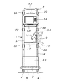
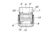
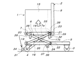
以下に本発明の好適実施形態を添付図に基づいて説明すると、図1〜図4において、1は端末装置搭載の補助台車であって、端末装置搭載フレーム2を、四隅に固定車輪3及び自在車輪4を備えた台車部5にパンタグラフリンク機構6を介して昇降自在に支持したものである。端末装置搭載フレーム2は、基台7の後端に門形フレーム本体8を立設したもので、門形フレーム本体8には、前方に突出する左右一対の把手枠9、上段の固定棚10、及び中段の横方向引き出し可能な可動棚11を備えている。この端末装置搭載フレーム2に搭載される端末装置12は、上段の固定棚10に搭載されるディスプレイ一体形のパーソナルコンピューター13と中段の可動棚11に搭載されるバーコードリーダー14、及びこれらに対する電源供給用バッテリーと制御盤を内蔵し且つ基台7に搭載されたバッテリーボックス15から構成されている。なお、端末装置12の構成は、この実施形態の構成に限定されないことは勿論である。
【0011】
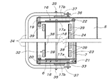
前記パンタグラフリンク機構6は、図4〜図6に示すように、左右一対のパンタグラフリンク16から成り、両パンタグラフリンク16は、2本のリンク17a,17bをその中央位置で互いに支軸18で枢着するとともに、両リンク17a,17bの前端は、台車部5の前端と端末装置搭載フレーム2の基台7の前端とに支軸19,20で枢着し、両リンク17a,17bの後端には、それぞれ端末装置搭載フレーム2の基台7を支持する状態で前後に転動するローラー21と台車部5の底板上を前後に転動するローラー22とがそれぞれ支軸23,24により軸支されている。なお、支軸18,23,24は、左右一対のパンタグラフリンク16間にわたって架設された共通軸である。
【0012】
前記端末装置搭載フレーム2には、その門形フレーム本体8の後側に上下複数段(図示例は3段)に付設された各左右一対のフック30が設けられている。また、前記フック30を利用して補助台車1を運搬台車に支持させた状態で当該補助台車1の台車部5の各車輪3,4を床面から浮上させる車輪浮上手段として、図4〜図7に示すように、床面上の台車部5に対し端末装置搭載フレーム2を、運搬台車に端末装置搭載フレーム2を係止させるための高さまで上昇させる操作手段31と、運搬台車に係止された端末装置搭載フレーム2に対して前記台車部5を引き上げる台車部引き上げ手段32とが設けられている。
【0013】
前記操作手段31は、両端が端末装置搭載フレーム2の基台7の左右両側に同心状の水平支軸33により支承された平面形状が門形の足踏みレバー34と、この足踏みレバー34の左右両側枠部の中間位置と台車部5とに両端が水平支軸35,36により軸支された左右一対のリンク37とから構成され、当該リンク37の台車部5側の水平支軸36は、足踏みレバー34の水平支軸33の下方に位置して、足踏みレバー34から見てリンク37が斜め後方下方に傾斜するように構成している。
【0014】
前記台車部引き上げ手段32は、図4〜図6に示すように、台車部5に対し端末装置搭載フレーム2が下降限位置にあるとき、下端吸着部が台車部5の底板(鉄板などの磁性板)5aに当接または近接するように、端末装置搭載フレーム2の基台7の下側にブラケット38を介して取り付けられた複数個の磁石39から構成されている。
【0015】
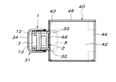
図7及び図8に示すように、上記構成の補助台車1と組み合わせられて使用される運搬台車40は、一般に周知のもので、自在車輪などの車輪41を備えた台車部42の周囲三側辺に側枠43〜45を立設し、開放側辺を開閉自在なバー46やゴムベルト47により閉じることができるようにしたものであり、対向側枠43,44を構成する上下複数段(図示例は3段)の水平部材を、補助台車1を着脱自在に係止する補助台車係止部48としている。
【0016】
補助台車1を運搬台車40に係止させて使用するときは、図3及び図4に示すように、端末装置搭載フレーム2が下降限にあって、その基台7が台車部5に受け止められている状態で、把手枠9を利用するなどして補助台車1を、運搬台車40に隣接する位置まで手押し走行させる。運搬台車40の補助台車係止部48がある側面に補助台車1の端末装置搭載フレーム2が隣接する位置まで補助台車1を走行させたならば、図6及び図7Aに示すように、操作手段31の足踏みレバー34を踏み降ろし、支軸18を中心とする足踏みレバー34の回転により、支軸33を介して端末装置搭載フレーム2を、台車部引き上げ手段32の磁石39と台車部5との間に働いている吸着力に抗して台車部5に対し押し上げる。このとき、パンタグラフリンク機構6の左右一対のパンタグラフリンク16により、台車部5に対し端末装置搭載フレーム2が平行上昇運動を行う。
【0017】
図7Aに示すように、補助台車1の端末装置搭載フレーム2が台車部5に対し上昇限高さまで押し上げられたとき、その各フック30は、同一床面上の運搬台車40における各段補助台車係止部48より若干高い位置にあるように構成されている。しかして、足踏みレバー34を踏み降ろした状態のまま、補助台車1を運搬台車40側へ接近移動させ、端末装置搭載フレーム2の門形フレーム本体8を運搬台車40の補助台車係止部48のある側枠43(または44)に当接させる。このとき、補助台車1側の各段フック30は、運搬台車40の各段補助台車係止部48に被さる位置になる。
【0018】
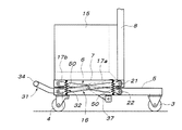
係る状態で、足踏みレバー34にかけていた踏み降ろし操作力を解除することにより、台車部5に対し押し上げられていた端末装置搭載フレーム2は重力により若干下降して、その各段フック30が運搬台車40の各段補助台車係止部48に係合することになる。一方、足踏みレバー34にかけていた踏み降ろし操作力を解除することにより、台車部5は、パンタグラフリンク機構6を介して端末装置搭載フレーム2に吊り下げられた状態になっているので、台車部引き上げ手段32の磁石39と台車部5との間に働いている吸着力により、台車部5が引き上げられ、図7Bに示すように、当該台車部5の各車輪3,4が床面から浮上することになる。
【0019】
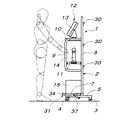
以上のようにして、図7B及び図8に示すように、補助台車1をフック30と補助台車係止部48とを介して運搬台車40の外側面に吊り下げた状態とすることにより、運搬台車40の手押し走行に伴って補助台車1が一体に移動することになるので、作業者は、端末装置12のパーソナルコンピューター13のディスプレイにより指示される作業内容に応じて、運搬台車40を棚の所定位置まで移動させた状態で、棚から所定の商品を取り出して運搬台車40に積み込むピッキング作業や、この逆の仕分け作業などを行うことができる。また、必要に応じて、ピッキングした商品や仕分け商品に貼付または印刷されているバーコードを、端末装置12のバーコードリーダー14により読み取らせ、データをパーソナルコンピューター13に入力することができる。
【0020】
作業終了後、運搬台車40はピッキングした商品の搬送などに利用し得るが、端末装置12が不要なときは、運搬台車40の外側に吊り下げられた状態の補助台車1における操作手段31の足踏みレバー34を踏み降ろして台車部5を端末装置搭載フレーム2に対し相対的に下降させる。そして、台車部5の車輪3,4が床面上に当接した後もさらに足踏みレバー34を踏み降ろすことにより、床面上に達した台車部5に対し端末装置搭載フレーム2を押し上げることができる。この端末装置搭載フレーム2の押し上げ操作により、当該端末装置搭載フレーム2側の各段フック30が運搬台車40側の補助台車係止部48から上方に離脱するので、足踏みレバー34を踏み降ろしたまま補助台車1を手前に引いて、補助台車1を運搬台車40から切り離すことができる。運搬台車40から補助台車1を切り離したならば、足踏みレバー34に対する踏み降ろし操作を解除して、押し上げていた端末装置搭載フレーム2を下降させて台車部5上に支持させれば良い。なお、この補助台車1単独でも、検品作業などにそのまま使用することができる。
【0021】
なお、図示のように補助台車1単独での床面上での手押し走行を安定的に行わせるため、台車部5を端末装置搭載フレーム2よりも後方に延出させているが、この補助台車1を運搬台車40の外側面に係止支持させたとき、当該台車部5の後方への延出部は、運搬台車40の台車部42の下側に入り込むように構成している。
【0022】
上記実施形態では、台車部引き上げ手段32に磁石を利用したが、図9に示すように、台車部5とこの上の基台7との間に介装した複数本の引張コイルスプリング50により、運搬台車40に係止支持された端末装置搭載フレーム2に対し台車部5を引き上げるように構成することもできる。また、このようにスプリングを利用する場合、そのスプリングは、パンタグラフリンク機構6内に配設することもできるし、パンタグラフリンク機構6と基台7または台車部5との間に介装することも可能である。さらに、端末装置搭載フレーム2を台車部5に対し昇降運動可能に支持する手段としては、パンタグラフリンク機構6に限定されない。
【0023】
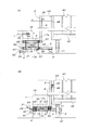
図10は、別の実施形態を示している。この実施形態では、係止手段51が設けられている。この係止手段51は、足踏みレバー34を踏み降ろして台車部5に対し端末装置搭載フレーム2を上昇限高さまで押し上げた状態で当該足踏みレバー34を自動係止する係止レバー52から成るもので、足踏みレバー34が踏み降ろされるときは、スプリング(図示省略)の付勢力に抗して揺動して足踏みレバー34の踏み降ろし操作を許すが、足踏みレバー34の上動復帰を許す方向には揺動できない逆止レバーであって、支軸53により台車部5に支承され、踏み降ろされた足踏みレバー34の係止を解除するための操作部54を備えている。
【0024】
この実施形態によれば、図10Aに示すように、足踏みレバー34を踏み降ろして台車部5に対し端末装置搭載フレーム2を上昇限高さまで押し上げた状態で当該足踏みレバー34を係止レバー52で係止させておくことにより、足踏みレバー34を踏み降ろした状態で補助台車1を運搬台車40側へ接近移動させなくとも、補助台車1側のフック30が運搬台車40側の補助台車係止部48の上に被さる位置まで単に補助台車1を手押し移動させれば良い。そして、補助台車1と運搬台車40とが隣接した状態で、操作部54により係止レバー52を足踏みレバー34から外すことにより、台車部5と端末装置搭載フレーム2との間の相対昇降運動が自由な状態になるので、図10Bに示すように、床面上の台車部5に対し端末装置搭載フレーム2が重力で若干下降して、フック30が運搬台車40側の補助台車係止部48に係合し、この後は台車部引き上げ手段32のスプリング50(または磁石39)により台車部5が引き上げられ、その車輪3,4が床面から浮上することになる。
【0025】
補助台車1を運搬台車40から切り離す場合は、単に足踏みレバー34を踏み降ろして係止レバー52に係止するだけで、先の実施形態と同様に、台車部5が着床した後、当該台車部5に対し端末装置搭載フレーム2が上昇限高さまで押し上げられて、フック30が補助台車係止部48から外れるので、補助台車1を運搬台車40から切り離すように移動させることができる。
【0026】
図11は、さらに別の実施形態を示すもので、前記補助台車1の台車部5と端末装置搭載フレーム2とを連結するガイド手段55が設けられている。このガイド手段55は、端末装置搭載フレーム2の基台7の前後2箇所にそれぞれ左右一対取り付けられた4つのカムレール56と、この各カムレール56に係合するように台車部5に軸支された4つのカム従動ローラー57とから構成されている。
【0027】
しかして、前記ガイド手段55は、端末装置搭載フレーム2に対し台車部5を後方に移動させることにより、当該台車部5と端末装置搭載フレーム2とを上下方向に相対離間させた第一状態(図11A)とし、端末装置搭載フレーム2に対し台車部5を前方に移動させることにより、当該台車部5と端末装置搭載フレーム2とを上下方向に相対接近させた第二状態(図11B)とするものであって、図11Aに示すように、前記台車部5が床面上にあって且つ前記第一状態にあるとき、端末装置搭載フレーム2が、前記運搬台車40の補助台車係止部48よりフック30が若干高くなる高さとなり、図11Bに示すように、前記運搬台車40の補助台車係止部48に端末装置搭載フレーム2のフック30が係止された状態で且つ前記第二状態にあるとき、前記台車部5の車輪3,4が床面から浮上するように構成している。
【0028】
この実施形態によれば、図11Aに示すようにガイド手段55で補助台車1を第一状態にしておけば、単に補助台車1を運搬台車40の側面に当接する位置まで手押し走行させるだけで、そのフック30を運搬台車40側の補助台車係止部48に被さるように位置させることができる。この後、台車部5を前方(運搬台車40のある側)へ押して移動させることにより、ガイド手段55により台車部5と端末装置搭載フレーム2とが相対的に接近移動して第二状態に移るので、その過程でフック30が台車係止部48に係合した後、台車部5が床面から浮上することになり、図11Bに示すように、運搬台車40の外側面に補助台車1が吊り下げられた状態になる。
【0029】
運搬台車40から補助台車1を切り離すときは、台車部5を前方(運搬台車40から離間させる方向)に引き出すことにより、ガイド手段55により台車部5と端末装置搭載フレーム2とが相対的に離間移動して第一状態に復帰するので、その過程で台車部5が床面に着床した後、フック30が台車係止部48から外れることになり、運搬台車40から補助台車1を切り離すことができる。
【0030】
なお、この実施形態においては、台車部5の押し込み及び引き出しに便利なように、図示のような把手部58を台車部5の後端に突設しておくことができる。また、第一状態と第二状態とを安定的に保持できるように、例えば図示のように、カムレール56の両端を傾斜させて、当該カムレール56の両端でカム従動ローラー57を重力の作用で安定させることができる。また、前記第一状態と第二状態とを択一的にロックするロック手段を併用することができる。さらに、ガイド手段55としてカムレール56とカム従動ローラー57とを使用したが、平行前後揺動リンク機構により台車部5を端末装置搭載フレーム2の基台7から吊り下げることもできる。
【0031】
【発明の効果】
以上のように本発明の端末装置付き運搬台車によれば、ピッキングや仕分け作業などを指示する端末装置が搭載された補助台車は、補助台車係止部を利用して運搬台車の側面に係止させることができ、しかもこの状態で、車輪浮上手段により前記補助台車の車輪を床面から浮上させることができるので、当該補助台車を単に運搬台車に連結して走行させる場合と比較して、運搬台車の操作性が低下することは殆どなく、安全且つ容易に運搬台車と端末装置搭載の補助台車とを一体に走行させることができる。また、補助台車に運搬台車を支持させるのではないので、補助台車は端末装置を安定的に支持し得るだけの小型軽量のもので良く、取り扱いに便利であるばかりでなく、全体を比較的安価に実施することができる。
【0032】
なお、請求項2に記載の構成によれば、補助台車の端末装置搭載フレームを台車部に対し上昇させて運搬台車の補助台車係止部に係止させるのであるから、運搬台車から切り離した状態の補助台車の高さを低くすることができ、補助台車単独での移動も安全に行える。この場合、請求項3に記載の構成によれば、運搬台車に補助台車を係止させて使用する状態で、振動などで補助台車の台車部が上下に揺れ動くことがなく、安定的に使用することができる。また、請求項4に記載の構成によれば、スプリングを利用して安価に実施することができる。
【0033】
さらに、請求項5に記載の構成によれば、補助台車を運搬台車に係止させるとき、当該補助台車の端末装置搭載フレームを台車部に対し上昇させた操作状態を維持しながら補助台車を運搬台車側へ移動させる必要がなく、運搬台車への補助台車の吊り下げ作業を容易に行える。
【0034】
また、請求項6に記載の構成によれば、足踏みレバーの踏み降ろし操作という簡単で力の入れ易い操作で補助台車の端末装置搭載フレームを台車部に対し上昇させることができる。
【0035】
さらに、請求項7に記載の構成によれば、台車部の押し引き操作で当該台車部に対し端末装置搭載フレームを昇降させることができ、しかも、運搬台車の補助台車係止部に端末装置搭載フレームを係止させ得る高さで当該端末装置搭載フレームを保持させることができるので、運搬台車への補助台車の係止操作を容易に行える。
【図面の簡単な説明】
【図1】 補助台車の正面図である。
【図2】 補助台車の平面図である。
【図3】 補助台車の側面図である。
【図4】 補助台車の要部を示す縦断側面図である。
【図5】 補助台車の要部を示す横断平面図である。
【図6】 補助台車の台車部に対し端末装置搭載フレームを上昇させた状態を示す要部の縦断側面図である。
【図7】 A図は補助台車を運搬台車に係止させる直前の状態を示す一部切り欠き側面図であり、B図は補助台車を運搬台車に係止させた状態を示す一部切り欠き側面図である。
【図8】 図7Bの平面図である。
【図9】 台車部引き上げ手段の変形例を示す要部の縦断側面図である。
【図10】 第二実施形態を示すもので、A図は補助台車を運搬台車に係止させる直前の状態を示す縦断側面図であり、B図は補助台車を運搬台車に係止させた状態を示す縦断側面図である。
【図11】 第三実施形態を示すもので、A図は補助台車を運搬台車に係止させる直前の状態を示す縦断側面図であり、B図は補助台車を運搬台車に係止させた状態を示す縦断側面図である。
【符号の説明】
1 補助台車
2 補助台車の端末装置搭載フレーム
5 補助台車の台車部
6 パンタグラフリンク機構
12 端末装置
13 ディスプレイ一体形のパーソナルコンピューター
14 バーコードリーダー
15 バッテリーボックス
16 左右一対のパンタグラフリンク
30 フック
31 操作手段(車輪浮上手段)
32 台車部引き上げ手段(車輪浮上手段)
34 足踏みレバー
37 リンク
39 磁石
40 運搬台車
48 補助台車係止部
50 スプリング
51 係止手段
52 係止レバー
55 ガイド手段
56 カムレール
57 カム従動ローラー[0001]
BACKGROUND OF THE INVENTION
The present invention is used for picking, sorting work, and the like, and relates to a transport cart provided with a terminal device for instructing the worker about the work contents and inputting product data.
[0002]
[Prior art]
As this type of conventional transport cart, as described in Japanese Patent Laid-Open No. 7-304456, a terminal device that is detachably attached to the outer surface of the transport cart is known. Combining a terminal device with a large and heavy battery so that it can withstand long-term use or use with a bar code reader is practically impossible, and it must be a small and lightweight terminal device including a power supply. In addition, the terminal device may fall and be damaged due to failure of the terminal device.
[0003]
Therefore, a method of combining an auxiliary cart equipped with a terminal device with a transport cart together with an auxiliary cart that can be easily installed even with a large and heavy terminal device including a battery, a large display, a barcode reader, etc. Was considered. For example, as described in JP-A-7-257713, an auxiliary carriage having a terminal device mounted on a carriage is detachably connected so that the two carriages can be connected and moved, As described in JP-A-301184, an auxiliary cart equipped with a terminal device is configured as a large portal-type cart that can support a carrier cart that floats from the floor. The thing which supported the transportation cart integrally was considered.
[0004]
[Problems to be solved by the invention]
However, in a configuration in which an auxiliary cart equipped with a terminal device is detachably connected to the transport cart so that the two carts can be connected and moved, the operability of the transport cart is reduced compared to the case of the transport cart alone. In addition, it becomes difficult to work safely and efficiently. In addition, in the method of supporting the transport carriage with the auxiliary carriage equipped with the terminal device, the auxiliary carriage becomes larger than the transport carriage, and the overall weight and occupied space are significantly larger than the case of the transport carriage alone. Sexuality also deteriorates.
[0005]
[Means for Solving the Problems]
An object of the present invention is to provide a transport carriage with a terminal device that can solve the conventional problems as described above, and the means thereof is shown with reference numerals of embodiments described later. It consists of a combination of the
[0006]
In carrying out the apparatus of the present invention having the above-described configuration, the
[0007]
Further, the terminal
[0008]
As the operation means 31, a
[0009]
Further, as the wheel floating means, a guide means 55 for connecting the
[0010]
DETAILED DESCRIPTION OF THE INVENTION
A preferred embodiment of the present invention will be described below with reference to the accompanying drawings. In FIGS. 1 to 4,
[0011]
The
[0012]
The terminal
[0013]
The operation means 31 has a gate-
[0014]
As shown in FIGS. 4 to 6, when the terminal
[0015]
As shown in FIGS. 7 and 8, a transporting
[0016]
When the
[0017]
As shown in FIG. 7A, when the terminal
[0018]
In this state, by releasing the stepping-down operation force applied to the stepping
[0019]
As described above, as shown in FIGS. 7B and 8, the
[0020]
After completion of the work, the
[0021]
In addition, as shown in the drawing, the
[0022]
In the above embodiment, a magnet is used for the carriage part lifting means 32. However, as shown in FIG. 9, a plurality of tension coil springs 50 interposed between the
[0023]
FIG. 10 shows another embodiment. In this embodiment, a locking means 51 is provided. The locking means 51 includes a locking
[0024]
According to this embodiment, as shown in FIG. 10A , the
[0025]
When the
[0026]
FIG. 11 shows still another embodiment, and a guide means 55 for connecting the
[0027]
Thus, the guide means 55 moves the
[0028]
According to this embodiment, as shown in FIG. 11A , if the
[0029]
When the
[0030]
In this embodiment, a
[0031]
【The invention's effect】
As described above, according to the transport cart with the terminal device of the present invention, the auxiliary cart equipped with the terminal device for instructing picking or sorting work is locked to the side surface of the transport cart using the auxiliary cart locking portion. In this state, the wheel of the auxiliary carriage can be lifted from the floor surface by the wheel floating means, so that the auxiliary carriage is transported as compared with the case where the auxiliary carriage is simply connected to the carriage. The operability of the carriage is hardly lowered, and the transport carriage and the auxiliary carriage equipped with the terminal device can be made to travel together safely and easily. Also, since the auxiliary carriage does not support the transport carriage, the auxiliary carriage may be small and light enough to stably support the terminal device, and is not only convenient for handling but also relatively inexpensive. Can be implemented.
[0032]
In addition, according to the structure of
[0033]
Further, according to the configuration of
[0034]
Further, according to the configuration of the sixth aspect, the terminal device mounting frame of the auxiliary cart can be raised with respect to the cart portion by a simple and easy operation of pushing down the foot lever.
[0035]
Furthermore, according to the structure of
[Brief description of the drawings]
FIG. 1 is a front view of an auxiliary cart.
FIG. 2 is a plan view of an auxiliary cart.
FIG. 3 is a side view of an auxiliary cart.
FIG. 4 is a longitudinal sectional side view showing a main part of the auxiliary cart.
FIG. 5 is a cross-sectional plan view showing a main part of the auxiliary cart.
FIG. 6 is a longitudinal side view of a main part showing a state in which the terminal device mounting frame is raised with respect to the carriage part of the auxiliary carriage.
FIG. 7A is a partially cutaway side view showing a state immediately before the auxiliary cart is locked to the transport cart, and FIG. 7B is a partially cutaway view showing the status where the auxiliary cart is locked to the transport cart. It is a side view.
FIG. 8 is a plan view of FIG. 7B.
FIG. 9 is a longitudinal sectional side view of a main part showing a modification of the cart part lifting means.
FIG. 10 shows a second embodiment, wherein FIG. A is a longitudinal side view showing a state immediately before the auxiliary cart is locked to the transport cart, and FIG. B is a state where the auxiliary cart is locked to the transport cart. FIG.
FIG. 11 shows a third embodiment, wherein FIG. A is a vertical side view showing a state immediately before the auxiliary cart is locked to the transport cart, and FIG. B is a state where the auxiliary cart is locked to the transport cart. FIG.
[Explanation of symbols]
DESCRIPTION OF
32 Bogie part lifting means (wheel floating means)
34
Claims (7)
Priority Applications (1)
| Application Number | Priority Date | Filing Date | Title |
|---|---|---|---|
| JP25872399A JP3672012B2 (en) | 1999-09-13 | 1999-09-13 | Carriage cart with terminal device |
Applications Claiming Priority (1)
| Application Number | Priority Date | Filing Date | Title |
|---|---|---|---|
| JP25872399A JP3672012B2 (en) | 1999-09-13 | 1999-09-13 | Carriage cart with terminal device |
Publications (2)
| Publication Number | Publication Date |
|---|---|
| JP2001080519A JP2001080519A (en) | 2001-03-27 |
| JP3672012B2 true JP3672012B2 (en) | 2005-07-13 |
Family
ID=17324202
Family Applications (1)
| Application Number | Title | Priority Date | Filing Date |
|---|---|---|---|
| JP25872399A Expired - Fee Related JP3672012B2 (en) | 1999-09-13 | 1999-09-13 | Carriage cart with terminal device |
Country Status (1)
| Country | Link |
|---|---|
| JP (1) | JP3672012B2 (en) |
Families Citing this family (3)
| Publication number | Priority date | Publication date | Assignee | Title |
|---|---|---|---|---|
| DE102011051330A1 (en) * | 2011-02-07 | 2012-08-09 | Luca Gmbh Versand & Logistiksysteme | Attachment frame for picking trolleys |
| JP7114440B2 (en) * | 2018-10-31 | 2022-08-08 | 西部電機株式会社 | Auxiliary equipment for transport carts |
| CN112918983B (en) * | 2021-02-04 | 2022-12-02 | 机械工业第九设计研究院股份有限公司 | Battery taking and placing device for automobile production line |
-
1999
- 1999-09-13 JP JP25872399A patent/JP3672012B2/en not_active Expired - Fee Related
Also Published As
| Publication number | Publication date |
|---|---|
| JP2001080519A (en) | 2001-03-27 |
Similar Documents
| Publication | Publication Date | Title |
|---|---|---|
| JP4978371B2 (en) | Conveyor using trolley | |
| CN103171841B (en) | Article transport facility | |
| WO2006016502A1 (en) | Carrying apparatus with lifting carried object support table | |
| JP2007153614A (en) | Work conveying apparatus and work conveying method | |
| JP4958003B2 (en) | Work equipment using transport carts | |
| JP2010214577A (en) | Door carrier | |
| JP5472824B2 (en) | Carriage carts in automobile assembly lines | |
| JP3406589B2 (en) | Unloading device | |
| JPS6040304A (en) | Housing system | |
| JP4328121B2 (en) | 6-wheel truck for transportation | |
| JP3672012B2 (en) | Carriage cart with terminal device | |
| JP4196348B2 (en) | Transport device | |
| JP5354183B2 (en) | Elevating transport equipment | |
| JP2010195069A (en) | Cargo carriage | |
| JPH08133467A (en) | Pallet transfer equipment for carrying in/out cargo | |
| JP2005145364A (en) | Loading/unloading vehicle | |
| CN218594460U (en) | Climbing mechanism of AGV dolly | |
| JP2006044925A (en) | Carrying device | |
| JP4258059B2 (en) | Entry / exit bogie equipment in warehouse facilities | |
| JP2000255723A (en) | Carriage device having elevating baggage receiver | |
| CN222629362U (en) | Logistics transportation trolley | |
| JPH07101510A (en) | Vertical transport device | |
| JP3246422B2 (en) | Transfer device | |
| JP3476054B2 (en) | Article storage facility | |
| KR200254413Y1 (en) | Manual balance |
Legal Events
| Date | Code | Title | Description |
|---|---|---|---|
| A977 | Report on retrieval |
Free format text: JAPANESE INTERMEDIATE CODE: A971007 Effective date: 20050104 |
|
| A131 | Notification of reasons for refusal |
Free format text: JAPANESE INTERMEDIATE CODE: A131 Effective date: 20050209 |
|
| A521 | Written amendment |
Free format text: JAPANESE INTERMEDIATE CODE: A523 Effective date: 20050210 |
|
| TRDD | Decision of grant or rejection written | ||
| A01 | Written decision to grant a patent or to grant a registration (utility model) |
Free format text: JAPANESE INTERMEDIATE CODE: A01 Effective date: 20050330 |
|
| A61 | First payment of annual fees (during grant procedure) |
Free format text: JAPANESE INTERMEDIATE CODE: A61 Effective date: 20050412 |
|
| R150 | Certificate of patent (=grant) or registration of utility model |
Free format text: JAPANESE INTERMEDIATE CODE: R150 |
|
| FPAY | Renewal fee payment (prs date is renewal date of database) |
Free format text: PAYMENT UNTIL: 20090428 Year of fee payment: 4 |
|
| FPAY | Renewal fee payment (prs date is renewal date of database) |
Free format text: PAYMENT UNTIL: 20100428 Year of fee payment: 5 |
|
| FPAY | Renewal fee payment (prs date is renewal date of database) |
Free format text: PAYMENT UNTIL: 20110428 Year of fee payment: 6 |
|
| FPAY | Renewal fee payment (prs date is renewal date of database) |
Free format text: PAYMENT UNTIL: 20110428 Year of fee payment: 6 |
|
| FPAY | Renewal fee payment (prs date is renewal date of database) |
Free format text: PAYMENT UNTIL: 20110428 Year of fee payment: 6 |
|
| FPAY | Renewal fee payment (prs date is renewal date of database) |
Free format text: PAYMENT UNTIL: 20120428 Year of fee payment: 7 |
|
| FPAY | Renewal fee payment (prs date is renewal date of database) |
Free format text: PAYMENT UNTIL: 20130428 Year of fee payment: 8 |
|
| FPAY | Renewal fee payment (prs date is renewal date of database) |
Free format text: PAYMENT UNTIL: 20130428 Year of fee payment: 8 |
|
| FPAY | Renewal fee payment (prs date is renewal date of database) |
Free format text: PAYMENT UNTIL: 20140428 Year of fee payment: 9 |
|
| LAPS | Cancellation because of no payment of annual fees |