JP3668276B2 - Method and apparatus for producing oxide single crystal - Google Patents
Method and apparatus for producing oxide single crystal Download PDFInfo
- Publication number
- JP3668276B2 JP3668276B2 JP06258695A JP6258695A JP3668276B2 JP 3668276 B2 JP3668276 B2 JP 3668276B2 JP 06258695 A JP06258695 A JP 06258695A JP 6258695 A JP6258695 A JP 6258695A JP 3668276 B2 JP3668276 B2 JP 3668276B2
- Authority
- JP
- Japan
- Prior art keywords
- single crystal
- crucible
- oxide single
- melt
- nozzle portion
- Prior art date
- Legal status (The legal status is an assumption and is not a legal conclusion. Google has not performed a legal analysis and makes no representation as to the accuracy of the status listed.)
- Expired - Lifetime
Links
Images


Description
【0001】
【産業上の利用分野】
本発明は、酸化物単結晶の製造方法およびその装置に関するものである。
【0002】
【従来の技術】
最近、酸化物単結晶を育成する方法として、いわゆるμ引下げ法によって単結晶ファイバーを形成する方法が注目を集めている。「電総研ニュース」1993年7月号(522号)の4〜8頁には、この方法によってニオブ酸・カリウム・リチウム(K3 Li2-2xNb5+x O15+x、以下、KLNと記載する。)単結晶ファイバーを育成した経緯が、開示されている。
【0003】
これによれば、白金製のセルないしルツボに電力を供給し、抵抗加熱する。このセルの底部に、溶融液の引出し口を形成し、この引出し口の中に、融液フィーダーと呼ばれる棒状体を挿通し、これによって溶融液の引出し口への供給量と、固相液相界面の状態とを共に制御する。溶融液引出し口の口径、フィーダーの太さ、引出し口からのフィーダーの突出長さ等を調整することによって、細径のKLN単結晶ファイバーを連続的に形成している。このμ引下げ法によれば、直径1mm以下の単結晶ファイバーを形成でき、熱歪みの低減、溶融液内の対流の制御、単結晶ファイバーの直径の制御を容易に行うことができ、特に青色第二高調波発生用に適した小型の高品質単結晶を生産できるという特徴を有している。
【0004】
【発明が解決しようとする課題】
本発明者は、上記のμ引下げ法によってKLN単結晶ファイバー等を量産するために、研究を重ねていた。量産技術として最も重要なことは、ルツボの規模を大きくして多量の溶融物を処理すること、およびこのルツボから単結晶ファイバーを長く連続的に引き下げるようにすることである。そこで、本発明者は、ルツボに投入する粉末の量を5g程度にまで増量し、これに合わせてルツボを大きくし、このルツボに電力を供給して発熱させ、原料粉末をルツボ内で溶融させて、マイクロ引下げ法を実施してみた。
【0005】
ところが、このようにルツボの規模を大きくし、粉末の溶融量を増大させると、ルツボの引出し口から溶融物を引き下げて単結晶を形成することが、きわめて困難であることが判明してきた。具体的には、ルツボを設置している炉の温度を900℃以下に低く設定し、主としてルツボへの通電によってルツボ内の粉末を溶融させると、引出し口付近での結晶成長が良好には行われなかった。即ち、ルツボに供給する電力を大きくすると、溶融液が引出し口で溶融し、結晶化せず、この電力を小さくすると、今度は引出し口付近で固体化してしまい、溶融液を引き出せなくなった。
【0006】
前記した炉の温度を900℃よりも高くすると、今度はルツボの全体が、炉からの輻射熱のために大きく加熱され、引出し口付近での温度勾配が非常に少なくなるために、やはり連続的に結晶成長を行わせることはできなかった。
【0007】
本発明の課題は、μ引下げ法によって酸化物単結晶を製造するのに際して、多量の原料を連続的に処理して、酸化物単結晶を量産できるようにすることである。
【0008】
【課題を解決するための手段】
本発明に係る酸化物単結晶の製造方法は、溶融ルツボと、この溶融ルツボよりも容量の小さい単結晶育成ルツボとを使用し酸化物単結晶の原料を溶融ルツボ内で溶融させ、この溶融した原料を、溶融ルツボの開口を通して単結晶育成ルツボへと連続的に供給し、この単結晶育成ルツボの引出し口の溶融物に対して種結晶を接触させ、この引出し口から下方へと向かって溶融物を引下げながら酸化物単結晶を育成することを特徴とする。
【0009】
また、本発明は、ルツボの引出し口の溶融物に対して種結晶を接触させ、この引出し口から下方へと向かって前記溶融物を引き下げながら前記酸化物単結晶を育成するための、酸化物単結晶の製造装置であって:
酸化物単結晶の原料を溶解させるための、開口を備えた溶融ルツボと、この溶融ルツボよりも容量の小さい単結晶育成ルツボとを備えており、
前記単結晶育成ルツボは前記引出し口を有するとともに、前記溶融ルツボ内で一旦溶融した原料を、前記開口を通して前記単結晶育成ルツボへと連続的に供給できるように構成されていることを特徴とする、酸化物単結晶の製造装置に係わるものである。
【0010】
【作用】
本発明者は、酸化物単結晶のμ引下げ法による量産技術を確立するべく、ルツボを大型化するための研究を続けていたが、ルツボを大型化していくと、引出し口から単結晶ファイバーを引き出せなくなり、この解決は困難であった。本発明者がこの原因を検討したところ、ルツボの底に引出し口を設け、この引出し口から直接に溶融物を引き出すという形態では、ルツボおよび溶融物の熱容量がある程度以上大きくなってくると、引出し口付近に対するルツボおよび溶融物の熱的影響によって、引出し口付近で良好な固相液相界面を形成することができないことがわかってきた。
【0011】
本発明者は、こうした知見にも係わらず、多量の原料を連続的に処理し、単結晶ファイバーを連続的に引出すことができるような方法を追求していたが、この過程で、溶融ルツボと、この溶融ルツボよりも容量の小さい単結晶育成ルツボとを別個に設け、酸化物単結晶の原料を溶融ルツボ内で溶融させ、この溶融した原料を、溶融ルツボの開口を通して単結晶育成ルツボへと連続的に供給し、この単結晶育成ルツボの引出し口の溶融物に対して種結晶を接触させ、この引出し口から下方へと向かって溶融物を引下げながら酸化物単結晶を育成することに想到した。
【0012】
この結果、溶融ルツボで溶融する原料粉末の量を、5g以上といった多量にし、これに合わせて溶融ルツボの容積を大きくしても、酸化物単結晶を連続的に容易に引き下げうることを見いだし、本発明に到達した。
【0013】
しかも、本発明によれば、単に多量の粉末を溶融させて、単結晶ファイバーを連続的に引き出すことができるというだけではない。本発明者は、従来の単結晶製造装置を使用し、しかしそのルツボ内の粉末の量は300〜500mg程度に抑えて、KLN単結晶ファイバーを連続的に引き出した。そして、その組成を精密に測定してみた。この結果、組成として1.0mol%程度の変動が生じていたことを発見した。
【0014】
これに対して、本発明の製造方法によれば、溶融ルツボ内で溶融する原料粉末の量を30〜50g程度にまで増大させ、この溶融物を、単結晶育成ルツボ内の量が300〜500mgになるように連続的に供給した場合でも、KLN単結晶ファイバーにおける組成の変動が、わずかに0.01mol%以下という驚くべき精度にまで減少していたことを発見した。このように、本発明の製造方法および装置によれば、単結晶の組成の均一性を向上させるという観点からも、従来のμ引下げ法と比較しても、驚くべき高精度を実現することができた。
【0015】
この理由は明瞭ではない。しかし、従来のμ引下げ法による製造装置では、ルツボに対して原料粉末を供給して、このルツボの内部で溶融させ、更にこのルツボに設けられた引出し口から単結晶ファイバーを引き出していた。従って、溶融ルツボの温度およびこの中の溶融物の温度は、溶融物が引出し口付近で固体化しないような高温に保持する必要があり、従って単結晶育成点である引出し口付近において、単結晶が固体化するような温度条件、温度勾配を維持することは困難であった。この理由から、たまたま特定の条件で単結晶ファイバーを引出し得たとしても、その組成等に不可避的にバラツキが発生したものと考えられる。
【0016】
これに対して、本発明では、溶融ルツボでいったん原料の溶融を行った後に、この溶融ルツボから単結晶育成ルツボへと原料を供給しており、単結晶育成ルツボは、溶融ルツボにおける高温の熱的影響を受けない。このため、単結晶育成ルツボの引出し口付近における温度条件を、溶融ルツボにおける温度条件とは別個に、独立して設定することができる。この結果、単結晶育成ルツボの引出し口付近の単結晶育成点における温度勾配を大きくして、良好な単結晶を引き出すことができる。
【0017】
この目的のためには、溶融ルツボと単結晶育成ルツボとを、それぞれ別個の加熱機構によって加熱することが好ましいし、また溶融ルツボと単結晶育成ルツボとの間隔を大きくすることが好ましく、このためには、溶融ルツボの下側面に下方向へと向かって延びるノズル部を形成し、このノズル部を通して、溶融ルツボ中でいったん溶融した原料を、連続的に単結晶育成ルツボへと供給することが好ましい。
【0018】
本発明においては、溶融ルツボで原料を溶融させ、このいったん溶融した原料を、単結晶育成ルツボへと連続的に供給する。原料を単結晶育成ルツボ中の溶融物に対して接触させる段階では、原料は溶融状態を保持していることが好ましいが、溶融ルツボの開口から排出されたところで固体化していても良い。ただし、固体化した原料が開口を閉塞しないようにするために、開口付近の固体化物を連続的に引き下げるか、または開口付近の固体物が、単結晶育成ルツボ内の溶融物に接触して直ちに溶融しうることが好ましい。
【0019】
【実施例】
更に、本発明者は、上記した製造装置を使用して、単結晶育成ルツボにおける溶融物の状態と、単結晶の物性との関係について研究した。この結果、単結晶育成部の環境に対して、重力よりも表面張力の方が支配的である場合には、きわめて組成の変動の少ない良好な酸化物単結晶を、連続的に引き出しうることを見いだした。これによって、良好な固相液相界面が形成されるからと思われる。
【0020】
更に、本発明者は、この点について追求した結果、次のような知見を得るに至った。即ち、従来のμ引下げ法においては、ルツボの規模が小さいので、単結晶ファイバーを連続的に引き下げることができたと考えられるが、これは、ルツボ内の溶融物の量が少なく、溶融物がルツボの壁面に対して、その表面張力によって張りつくことから、引出し口へと加わる重力が相対的に小さくなっていたために、ある程度は均質な固相液相界面が形成されたものと推定できる。しかし、ルツボの寸法を大きくすると、引出し口付近において表面張力が支配的な条件が失われたものと推定される。
【0021】
更に、本発明においては、単結晶育成ルツボの育成点付近において、温度勾配を大きくすることが容易である。これによって、溶融物を急速に冷却できる。
【0022】
従って、本発明は、固溶体単結晶を製造する場合に、特に適している。固溶体単結晶においては、平衡条件では組成比率が変動していく性質がある。従来のμ引下げ法を使用した場合には、引出し口付近では平衡条件なので、ちょっとした温度変化や固体化の速度の変化によって、固溶体の組成が変動していたが、こうした原因によるものと考えられる。これに対して、本発明の方法および装置によれば、単結晶育成部付近での急速冷却が可能なので、溶融物の組成を保持することができる。
【0023】
このような固溶体としては、例えば、KLN、KLTN〔K3 Li2-2x(Tay Nb1-y )5+x O15+x〕、Ba1-X SrX Nb2 O6 を中心としたタングステンブロンズの構造やMn−Znフェライトを例示することができる。
【0024】
更に、上記した理由から、組成偏析する酸化物単結晶を製造することができる。例えば、LiNbO3 に対してネオジムを固溶させる場合、その偏析係数が1でないことによって、溶融物の組成におけるネオジムの量よりも少ない量のネオジムしか単結晶中に入らない。例えば、溶融物内では1.0モル程度のネオジムが含有されていても、単結晶中には0.3モル程度しか入らない。しかし、本発明によれば、前記したように溶融物をノズル部内で急速に冷却することによって、偏析を招くことなく、溶融物の組成と同様の組成を有する単結晶を製造することができる。これは、他のレーザー単結晶、例えば、Nd、Er、Ybによって置換されたYAG、Nd、Er、Ybによって置換されたYVO4 に対しても、適用することができる。
【0025】
本発明の製造装置においては、ルツボの加熱方法は特に限定されない。しかし、単結晶製造装置の周囲を囲むように、加熱炉を設けることが好ましい。この際、加熱炉を上側炉と下側炉とに分離し、溶融ルツボを上側炉によって包囲し、この上側炉の方を相対的に高温で発熱させて、溶融ルツボ内の粉末の溶融を助けることが好ましい。
【0026】
これに対して、単結晶育成ルツボの周囲に下側炉を設置し、この下側炉の方の温度を相対的に低くすることによって、単結晶育成ルツボの育成部における温度勾配を大きくすることが好ましい。
【0027】
更に、溶融ルツボ内での粉末の溶融の効率を向上させるためには、溶融ルツボの外側の加熱炉のみによって溶融ルツボを加熱するよりも、溶融ルツボ自体を導電性材料によって形成し、この溶融ルツボに電力を供給することによって発熱させることが好ましい。
【0028】
更に、溶融ルツボのノズル部内を流れる溶融物の溶融状態を保持するためには、ノズル部を導電製材料によって形成し、このノズル部に電力を供給することによって発熱させることが好ましい。または、溶融ルツボのルツボ本体部分やノズル部を高周波誘導によって発熱させるための高周波加熱機構を備えることが好ましい。
【0029】
こうした導電性材料としては、特に耐食性の観点から、白金、白金−金合金、白金−ロジウム合金、白金−イリジウム合金、イリジウム等の材料が好ましい。
【0030】
ただし、白金等の耐食性金属は、いずれも抵抗率が比較的に低いので、これに電力を供給して有効に発熱させるためには、ノズル部の厚さを小さくすることによって、その抵抗値をある程度以上大きくする必要がある。例えば、白金によってノズル部を形成した場合には、100〜200μm程度の薄膜によって形成する必要があった。しかし、このように薄い膜によってノズル部を形成すると、構造的に弱くなり、ノズル部が変形して、安定した単結晶の生産が困難になる場合があった。
【0031】
そこで、ノズル部を包囲するように抵抗発熱材を設置し、抵抗発熱材に対して電力を供給することによってこの抵抗発熱材を発熱させることができる。この場合には、ノズル部の方を上述のように耐食性金属によって形成し、これに通電して発熱させることもできるが、電力を供給しなくともよい。このように、ノズル部を包囲する抵抗発熱材の方に主要な加熱機能を付与すれば、ノズル部に要求される発熱の負荷は小さくなり、またノズル部は発熱させなくとも良くなるので、ノズル部の方を厚くする(例えば500μm以上)ことによって、ノズル部の機械的強度を向上させることができ、量産に適した装置とすることができる。
【0032】
更に、本発明の製造装置によれば、溶融ルツボに対して原料を連続的に、または間欠的に供給することができる。なぜなら、溶融ルツボに対して原料を供給すると、その原料の溶解熱によって、溶融ルツボ内の熱的状態に変動が発生し、単結晶の組成の変動等がこれによって発生する。しかし、本発明によれば、溶融ルツボ内でこうした熱的変動が発生しても、単結晶育成ルツボへの熱的影響はきわめて少なく、かつ単結晶育成ルツボの育成部では、平衡状態ではなく、速度論的状態なので、熱的変動の影響をますます受けにくい。
【0033】
本発明は、単結晶ファイバーの製造だけでなく、単結晶からなる板状体ないしプレートの製造に対しても、良好に適用することができる。この具体的方法については後述する。
【0034】
KLN単結晶は、最近、光材料として注目を集めており、特に半導体レーザー用の青色光第二高調波発生(SHG)素子用の単結晶として注目されている。これは、390nmの紫外光領域まで発生することが可能であるので、こうした短波長の光を利用することで、光ディスクメモリー用、医学用、光化学用、各種光計測用等の幅広い応用が可能である。また、KLN単結晶は、電気光学効果も大きいのて、そのフォトリフラクティブ効果を利用した光記憶素子等にも適用できる。
【0035】
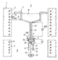
以下、図面を参照しつつ、更に詳細に本発明の実施例を説明する。図1は、単結晶育成用の製造装置を示す概略断面図であり、図2は、単結晶育成ルツボ16の部分を拡大して示す概略断面図である。図3(a)、(b)は、単結晶育成部の状態を模式的に示す断面図である。
【0036】
炉体の内部には、溶融ルツボ7が設置されている。溶融ルツボ7およびその上側空間5を包囲するように、上側炉1が設置されており、上側炉1内にはヒーター2が埋設されている。溶融ルツボ7の下端部から下方向へと向かってノズル部13が延びており、ノズル部13の下端部に開口13aが形成されている。ノズル部13の開口の真下に単結晶育成ルツボ16が設置されている。上側炉と下側炉との境界部分付近に単結晶育成ルツボ16が設置されている。単結晶ファイバーの引下げ部分およびその周囲の空間6を包囲するように、下側炉3が設置されており、下側炉3の中にヒーター4が埋設されている。むろん、こうした加熱炉の形態自体は、種々変更することができる。
【0037】
溶融ルツボ7、ノズル部13および単結晶育成ルツボ16は、いずれも耐食性の導電性材料によって形成されている。溶融ルツボ7の上端Aに対して、電源10Aの一方の電極が電線9によって接続されており、溶融ルツボの下側の折曲部Bに対して、電源10Aの他方の電極が接続されている。ノズル部13の上端Cに対して、電源10Bの一方の電極が電線9によって接続されており、ノズル部13の下端Dに対して他方の電極が接続されている。
【0038】
同様に、単結晶育成ルツボ16の端部Eに対して、電源10Cの一方の電極が電線9によって接続されており、単結晶育成ルツボの端部Fに対して、電源10Cの他方の電極が接続されている。これらの各通電機構は、共に分離されており、独立してその電圧を制御できるように構成されている。単結晶育成ルツボの下に、空間6内にアフターヒーター12が設けられている。
【0039】
なお、炉体(発熱体と耐火物)によってノズル部分の温度勾配が最適化されている場合には、アフターヒーター12は必ずしも必要ではない。
【0040】
上側炉1および下側炉3を発熱させて空間5、6の温度分布を適切に定め、溶融物の原料を溶融ルツボ7内に供給し、溶融ルツボ7、ノズル部13および単結晶育成ルツボ16に電力を供給し、それぞれ発熱させる。そして、溶融ルツボ7内の原料を溶融させて溶融物8を生成させる。この溶融物8は、ノズル部13内の流路15内を流下するが、この間、ノズル部13の発熱とアフターヒーター12とによって、その溶融状態が保持される。
【0041】
この溶融物は、開口13aから単結晶育成ルツボ16内へと流入する。単結晶育成ルツボ16内では、溶融物19が貯留される。
【0042】
または、この開口13aから流下した溶融物を、開口の直下で固形化して多結晶体とし、この多結晶体からなるフアイバーまたはプレートを単結晶育成ルツボ16内へと連続的に供給し、このフアイバーまたはプレートを単結晶育成ルツボ16内で溶融することもできる。
【0043】
単結晶の引出しを開始する前の段階では、図2および図3(a)に示すように、ノズル部17の下端部にある単結晶育成部18では、開口17aから溶融物19が僅かに突出し、その表面張力によって保持されて、比較的に平坦な表面24が形成されている。
【0044】
そして、溶融ルツボとは異なり、単結晶育成ルツボ16では、材料の溶融を行わず、溶融ルツボよりも小さいルツボを使用している。こうした小型のルツボの内部ではルツボ16の垂直な側壁面16aおよび底面16bの形状に沿った形で溶融物19が表面張力によって引っ張られ、この結果、溶融物19の液面23が、内側が凹んだ形状となる。従って、ノズル部17内の溶融物19に対して加わる重力は、単結晶育成ルツボ16の壁面16a、16bに対する溶融物19の接触によって、大きく減少している。
【0045】
この状態で、種結晶25を矢印Gで示すように上方向へと移動させ、種結晶25の端面25aを、溶融物の表面24に対して接触させる。次いで、図3(b)に示すように、種結晶25を矢印Hの方向へと引下げる。この際、種結晶25の上端部と、ノズル部17から下方向へと引き出されてくる溶融物19との間には、均一な固相液相界面(メニスカス)26が形成される。
【0046】
この結果、図1に示すように、種結晶25の上側に単結晶ファイバー20が連続的に形成され、下方向へと向かって引き出されてくる。本実施例では、この種結晶25および単結晶ファイバー20を、ローラー22によって送っている。
【0047】
一方、従来の方法に従い、ルツボ内に投入する粉末の量を増加させた場合には、ルツボの開口から下方向へと向かって、溶融物による膨張部分が形成される。更に、粉末の重量が大きい場合には、粉末を溶融させたときに溶融物が流れてしまい、この状態で種結晶25の端面25aを溶融物に対して接触させると、良好な固相液相界面が形成されない。
【0048】
図4は、他の実施例に係る製造装置におけるルツボの形態を、概略的に示す概略断面図である。図4において、図1にのものと同じ機能部材には同じ符号を付け、その説明は図1における説明を援用することにする。
【0049】
溶融ルツボ7の下端部からノズル部30が延びており、ノズル部30の下端部に開口30aが形成されており、この開口30aから単結晶育成ルツボ16へと、連続的に溶融物またはその固形化体を供給する。
【0050】
溶融ルツボ7およびノズル部30は、いずれも耐食性材料によって形成されている。溶融ルツボ7の上端Aと下側の折曲部Bとに対して、電源10Aの電極が接続されている。ノズル部30の周囲を囲むように、円管形状の発熱体31が設置されている。発熱体31の上端Iに対して、電源10Bの一方の電極が電線9によって接続されており、発熱体31の下端Jに対して他方の電極が接続されている。これらの各通電機構は、共に分離されており、独立してその電圧を制御できるように構成されている。
【0051】
また、ノズル部30を加熱するために、その周囲に図示しない高周波加熱機構を設置し、ノズル部30を加熱して溶融物の供給を制御することも可能であった。
【0052】
上記の各実施例においては、溶融ルツボのノズル部についても、単結晶育成ルツボのノズル部についても、円筒形状のノズル部を使用した。しかし、このような円筒形状のノズル部は、一般的に加工による製作のコストが高い。例えば、白金等の貴金属からなる材料を加工することによって、内径の小さなノズル部を形成することは困難である。
【0053】
そこで、本発明者は、耐食性金属や耐食性セラミックスからなる耐食性部材に溝を形成し、これを他の耐食性部材と貼り合わせたり、接合することによってノズル部を形成した。このノズル部内では、前記の溝が、細長い微細径の溶融物流通孔となる。こうした耐食性部材の形状は、溝を形成する側が平坦面であれば良いが、平板形状のものが好ましい。
【0054】
この際、両方の平板に前記の溝を形成し、両方の平板を貼り合わせるときにこれらの溝を一体化させることで、溶融物流通孔を形成することができる。または、一方の平板に前記の溝を形成し、他方の平板は平坦なままに放置し、両方の平板を貼り合わせるときに、一方の平板上に形成された前記溝によって、溶融物流通孔を形成することができる。こうしたノズル部は、溶融ルツボにも使用できるし、単結晶育成ルツボにも使用できる。
【0055】
更に、本発明者は、単結晶育成ルツボにおいて、ノズル部に複数列の溝を互いに平行に形成し、各溝によって各溶融物流通孔を形成し、各溶融物流通孔から同時に溶融物を流しだすことによって、単結晶プレートを形成することができた。
【0056】
単結晶育成ルツボにこのノズル部を形成する場合には、各溝の幅は0.01mm〜0.5mmとすることが好ましく、各溝の間隔は0.1〜10mmとすることが好ましい。また、これらの各溝の断面形状は、四角形、V字形状、半円形等とすることができる。
【0057】
具体的には、図5(a)に示すように、細長い平板32を準備し、図5(b)に示すように、この平板32の長手方向に延びるように、細長い溝33を形成する。こうした溝33を各平板32に形成し、図5(c)に示すように、各平板32を貼り合わせて、ノズル部34を形成し、ノズル部34の中に溶融物流通孔35を形成する。
【0058】
図5(d)に示すように、ルツボ36の底部36aに、ノズル部34が接合されており、ノズル部34の溶融物流通孔35内を溶融物が流下する。こうした方法であれば、単結晶ファイバーを形成するためのノズル部を、容易に製造することができる。このルツボは、溶融ルツボとしても使用できるし、単結晶育成ルツボとしても使用できる。
【0059】
次に、単結晶プレートを製造するための具体的なノズル部の形態について、好適例を説明する。図6(a)に示すように、平板37に複数列の細長い溝38を、互いに平行となるように形成する。図6(b)に示すように、各平板37を貼り合わせて、平板形状のノズル部39を形成し、ノズル部39の中に複数列の溶融物流通孔41を形成する。40は継ぎ目である。
【0060】
図6(c)に示すように、長方形状の溶融ルツボ42の底部に、ノズル部39が接合されている。この溶融ルツボ42内の溶融物は、ノズル部39の各溶融物流通孔41内を流下し、各溶融物流通孔41から流れだす。このとき、各溶融物流通孔41から流れだした溶融物が、ノズル部39の底面39a上で一体となって流れ、溶融物または多結晶の状態43で、単結晶育成ルツボに供給される。
【0061】
また、図7に示す実施例においては、各ノズル部として管状体46を使用し、各管状体46を配列し、この際各管状体46の外周面が連続するように設置する。ただし、図7においては、ルツボの部分は図示を省略したが、例えば図6(c)に示すようなルツボを使用することができる。各ノズル部46の中には溶融体の流通孔45が形成されており、各流通孔45は各管状体46の下端の底面46aに開口している。
【0062】
ルツボ内の溶融物は、各ノズル部46の各溶融物流通孔45内を流下し、各溶融物流通孔45から流れだす。このとき、各溶融物流通孔45から流れだした溶融物は、各ノズル部46の底面46a上で一体となって流れ、溶融物または多結晶の状態43で、単結晶育成ルツボに供給される。
なお、その下部の単結晶育成ルツボのノズル部も、これと同様の形状のものを短くして使用することにより、前記ファイバー状単結晶の場合と同様に、安定して単結晶プレートを製造することができた。
【0063】
以下、更に具体的な実験結果について述べる。
(実験1)
図1に示すような単結晶製造装置を使用し、本発明に従ってKLN単結晶ファイバーを製造した。上側炉1と下側炉3とによって炉内全体の温度を制御した。ノズル部13、単結晶育成ルツボ16に対する電力供給とアフターヒーター12の発熱とによって、単結晶育成部近辺の温度勾配を制御できるように構成した。単結晶ファイバーの引下げ機構としては、垂直方向に2〜100mm/時間の範囲内で、引下げ速度を均一に制御しながら、単結晶ファイバーを引き下げる機構を搭載した。
【0064】
炭酸カリウム、炭酸リチウムおよび酸化ニオブを、30:20:50の組成比率で調合して原料粉末を製造した。原料粉末約50gを、白金製の溶融ルツボ7内に供給し、この溶融ルツボ7を所定位置に設置した。ノズル部13の外側および内側の横断面の形状は円形とし、外径は1mmとし、内径は0.3mmとし、長さは20mmとした。溶融ルツボ7の平面形状は円形とし、その直径は30mmとし、その高さは30mmとした。単結晶育成ルツボ16の寸法は、原料約1gを収容しうる大きさとした。ノズル部は、外径1.2mm、内径0.8mmのパイプ2mmを使用した。
【0065】
上側炉1内の空間5の温度を1100〜1200℃の範囲に調整し、溶融ルツボ7内の原料を融解させた。下側炉3内の空間6の温度は、500〜1000℃に均一に制御した。溶融ルツボ7、ノズル部13に対して所定の電力を供給し、溶融物の単結晶育成ルツボ16への供給を制御した。アフターヒーター12、単結晶育成ルツボ16への供給電力を制御した。この結果、単結晶育成部の温度を1050℃〜1150℃とすることができ、単結晶育成部における温度勾配を10〜150℃/mmに制御することができた。
【0066】
この状態で、20mm/時間の速度で単結晶ファイバーを引き下げたところ、良好なKLN単結晶ファイバーを引き下げうることが判明した。
【0067】
更に、こうして育成した、縦1mm、横1mm、長さ100mmの単結晶ファイバーについて、この単結晶ファイバーを長さ方向(育成した方向)に見たときの組成分布について検査した。具体的には、SHG位相整合波長を単結晶ファイバーの長さ方向の各部分に対して照射し、その出力光の波長を測定した。KLN単結晶の組成が僅かでも変動すれば、その組成変動によって、SHG位相整合波長に変化が生じてくる。
【0068】
この測定を実施したところ、1nm以下の精度、即ち、組成に換算すると0.01mol%以下の、KLN単結晶としてかつてない高い精度で、組成を制御することができた。また、その波長変換効率も、ほぼ±2%以下の測定誤差の範囲内で、理論値とほぼ同一の測定値が得られた。
【0069】
(実験2)
実験1と同様にして、KLN単結晶ファイバーを育成した。ただし、溶融ルツボ7へと間欠的に原料を投入する原料供給機構を、炉内に設けた。また、炉の下に単結晶ファイバーを間欠的に所定長さで切断する機構を設けることによって、連続的に単結晶ファイバーを育成した。単結晶ファイバーの育成が進行してくるのにつれて、育成した単結晶の量および溶融ルツボ7から揮発した成分の量に相当する量の原料粉末を、溶融ルツボ7内へと供給した。こうして、長さほぼ10mの単結晶ファイバーを連続的に形成し、その組成変動を、実験1と同様の方法で測定した。この結果、ほぼ10mの長さの全長にわたって、その組成変動を0.01mol%以下に抑制することに成功した。
【0070】
(実験3)
図6に示すようなノズル部39およびルツボ42を使用し、厚さ1mm、長さ100mmのKLN単結晶プレートを引き下げることに成功した。ただし、平板37としては寸法30mm×30mm×0.6mmの白金板を使用した。この白金板に、ダイシング加工によって溝38を形成した。ただし、溝38の間隔は5mmとし、溝38の幅は0.1mmとした。2枚の白金板を接合することによって、厚さ1.2mmの平板形状のノズル部を形成した。また、単結晶育成用ルツボのノズル部としては、図7に示すようなパイプ状ノズルを並べたものを使用し、外径1mm、内径0.6mm、長さ2mmのパイプ30個を一列にならべて使用した。図6(a)〜(c)を参照しつつ説明したようにして、溶融物を各溶融物流通孔から流した。単結晶プレートの内部でのSHG位相整合波長と変換効率とを測定したところ、前記した単結晶ファイバーの場合と同様の値が得られた。
【0071】
(実験4)
LiNbO3 内にネオジムを固溶させた単結晶を育成する方法に対して、本発明を適用した。ただし、この系においては、例えばCZ法を使用した場合には、ネオジムの固溶量は0.3mol%程度である。
【0072】
酸化ネオジム、炭酸リチウム、酸化ニオブをmol比率で1:49:50の組成比率に調合し、原料粉末を製造した。実験1と同様の単結晶ファイバー製造装置を使用した。上記の原料粉末約50gを溶融ルツボ7内に収容した。上側炉1内の空間5の温度を1250〜1350℃の範囲に調整し、溶融ルツボ7内の原料を融解させた。下側炉3内の空間6の温度は、500〜1200℃に均一に制御した。ノズル部13、単結晶育成ルツボ16に対する電力供給とアフターヒーター12の発熱とによって、単結晶育成部近辺の温度勾配を制御した。
【0073】
この際、単結晶育成部の温度を1200℃〜1300℃とし、単結晶育成部における温度勾配を10〜150℃/mmに制御した。この状態で、20mm/時間の速度で単結晶ファイバーを引き下げたところ、良好なNd─LiNbO3 単結晶ファイバーを引き下げうることが判明した。
【0074】
更に、こうして育成した、縦1mm、横1mm、長さ100mmの単結晶ファイバーについて、この単結晶ファイバーを長さ方向(育成した方向)に見たときの組成分布について、EPMAによって元素分析した。この結果、原料粉末における組成ではネオジムの比率を1.0mol%にしたが、単結晶ファイバーでは、1.0mol%に対して±2%の検出限界以下の精度で、組成が制御されていたことが判明した。
【0075】
(比較実験1)
従来の構造の製造装置を使用し、実験1と同様のKLN単結晶ファイバーを作成した。原料粉末の量は500mgとした。ルツボは白金によって作成した。上側炉と下側炉とによって炉内全体の温度を制御した。上側炉内の空間の温度を1100〜1200℃の範囲に調整し、ルツボ内の原料を融解させた。下側炉3内の空間6の温度は、500〜1000℃に均一に制御した。ルツボに対して電力を供給し、これによって引出し口からの単結晶の育成、引出しを制御しようと試みた。この状態で、20mm/時間の速度で単結晶ファイバーを引き下げたところ、KLN単結晶ファイバーを引き下げることができた。
【0076】
こうして製造した、縦1mm、横1mm、長さ100mmの単結晶ファイバーについて、この単結晶ファイバーを長さ方向(育成した方向)に見たときの組成分布について、実験1と同様にして検査した。この結果、出力光の波長に、50nmの変動があった。これは、組成に換算すると1.0mol%を越えており、SHG素子用としては、実用上問題があるレベルであった。
【0077】
(比較実験2)
比較実験1において、ルツボから引き出された成分およびルツボから蒸発した成分の量に相当する量の原料粉末を、ルツボへと定期的に供給し、連続的に単結晶ファイバーを育成することを試みた。しかし、一度原料を供給すると、ルツボ内での熱平衡状態が大きく崩れたため、単結晶ファイバーの育成の継続は不可能になった。
【0078】
(比較実験3)
比較実験1において、ルツボの寸法を大きくし、ルツボに最初に投入する原料粉末の量を5gにまで増加させた。上側炉と下側炉とによって炉内全体の温度を制御し、ルツボに対して電力を供給し、これによって引出し口からの単結晶の育成、引出しを制御しようと試みた。
【0079】
しかし、上側炉内の温度を500〜900℃と低く調整すると、ルツボに対する電力供給量を多くして、ルツボ内の原料粉末の融解を促進する必要があるが、この出力を大きくすると溶融物が結晶化しなくなった。一方ルツボへの供給電力を小さくしていくと、引出し口から出る前に溶融物が固体化してしまった。このように、単結晶を引き出す条件を見いだすことはできなかった。
【0080】
一方、上側炉の温度を900℃以上とすると、炉体からの熱輻射によって、結晶成長点である引出し口付近で、結晶化に必要な温度勾配を維持することはできなくなり、やはり単結晶ファイバーを引き下げることはできなかった。
【0081】
【発明の効果】
以上述べたように、本発明によれば、μ引下げ法によって酸化物単結晶を育成するのに際して、多量の原料を処理して連続的に多量の酸化物単結晶を引き下げて形成することができ、しかもこの酸化物単結晶の組成の変動等を防止して、高品質の酸化物単結晶を製造することができる。従って、本発明は、こうした酸化物単結晶のファイバー等を量産する上で、きわめて重要な技術である。
【図面の簡単な説明】
【図1】本発明の実施例に係る、単結晶育成用の製造装置を示す概略断面図である。
【図2】図1の製造装置において、単結晶育成ルツボ16の周辺を概略的に示す概略断面図である。
【図3】(a)、(b)は、単結晶育成ルツボ16の先端部分の状態を説明するための概念図である。
【図4】本発明の他の実施例の製造装置において、ルツボの構成を概略的に示す概略断面図である。
【図5】(a)は、耐食性材料からなる平板32を示す平面図であり、(b)は、この平板32に溝33を形成した状態を示す平面図であり、(c)は、一対の平板32を接合することによって形成したノズル部34を示す断面図であり、(d)は、このノズル部34を取り付けたルツボ36を示す断面図である。
【図6】(a)は、耐食性材料からなる平板37に複数列の溝38を形成した状態を示す平面図であり、(b)は、一対の平板37を接合することによって形成したノズル部39を示す断面図であり、(c)は、このノズル部39を取り付けた単結晶育成ルツボ42を示す断面図である。
【図7】管状体からなるノズル部46を複数個互いに接触させて直線状に配列した状態を示す破断斜視図である。
【符号の説明】
1 上側炉 2、4 炉内のヒーター 3 下側炉 5 上側炉1内の空間 6 下側炉3内の空間 7 溶融ルツボ 8、19 溶融物 10A、10B、10C 交流電源(通電機構) 12 アフターヒーター 13、30 ノズル部 13a、30a ノズル部の開口 15 溶融物の流路 16、42 単結晶育成ルツボ 17 単結晶育成ルツボのノズル部 18 単結晶育成部 20 単結晶ファイバーないしプレート 22 ローラー 23 単結晶育成ルツボ内の溶融物の液面 25 種結晶 26 固相液相界面(メニスカス) 43 溶融物または多結晶、単結晶等の固化物 46 パイプ状のノズル部 A 溶融ルツボの上端 B 溶融ルツボの下側の曲折部 C ノズル部の上端 D ノズル部の下端 E、F 単結晶育成ルツボの端部[0001]
[Industrial application fields]
The present invention relates to a method for manufacturing an oxide single crystal and an apparatus therefor.
[0002]
[Prior art]
Recently, as a method for growing an oxide single crystal, a method of forming a single crystal fiber by a so-called μ pulling method has attracted attention. On the 4th to 8th pages of "Electronics Research News" July 1993 (No. 522), niobate, potassium, lithium (K Three Li 2-2x Nb 5 + x O 15 + x Hereinafter, it is described as KLN. ) History of growing single crystal fiber is disclosed.
[0003]
According to this, electric power is supplied to a platinum cell or crucible, and resistance heating is performed. A melt outlet is formed at the bottom of the cell, and a rod-like body called a melt feeder is inserted into the outlet, thereby supplying the melt to the outlet and the solid phase liquid phase. Control both the state of the interface. By adjusting the diameter of the melt outlet, the thickness of the feeder, the protruding length of the feeder from the outlet, etc., a small-diameter KLN single crystal fiber is continuously formed. According to this μ pulling-down method, a single crystal fiber having a diameter of 1 mm or less can be formed, heat distortion can be reduced, convection in the melt can be easily controlled, and the diameter of the single crystal fiber can be easily controlled. It is characterized by the ability to produce small high-quality single crystals suitable for second harmonic generation.
[0004]
[Problems to be solved by the invention]
The present inventor has repeatedly studied in order to mass-produce KLN single crystal fibers and the like by the above-described μ-lowering method. The most important mass production technique is to increase the scale of the crucible to process a large amount of melt and to continuously pull the single crystal fiber from the crucible for a long time. Therefore, the present inventor increased the amount of powder to be charged into the crucible to about 5 g, enlarged the crucible accordingly, supplied electric power to the crucible to generate heat, and melted the raw material powder in the crucible. I tried the micro pull-down method.
[0005]
However, when the size of the crucible is increased and the melting amount of the powder is increased, it has been found that it is very difficult to form a single crystal by pulling down the melt from the crucible outlet. Specifically, when the temperature of the furnace in which the crucible is installed is set low to 900 ° C. or less and the powder in the crucible is melted mainly by energizing the crucible, the crystal growth near the outlet is performed well. I wasn't. That is, when the electric power supplied to the crucible is increased, the melt is melted and does not crystallize at the outlet, and when this electric power is decreased, the melt is solidified near the outlet and the melt cannot be drawn.
[0006]
If the temperature of the furnace is raised above 900 ° C., the entire crucible is heated greatly due to the radiant heat from the furnace, and the temperature gradient near the outlet becomes very small. Crystal growth could not be performed.
[0007]
An object of the present invention is to process a large amount of raw materials continuously when manufacturing an oxide single crystal by a μ pulling down method so that the oxide single crystal can be mass-produced.
[0008]
[Means for Solving the Problems]
The method for producing an oxide single crystal according to the present invention uses a melting crucible and a single crystal growing crucible having a smaller capacity than the melting crucible to melt the raw material of the oxide single crystal in the melting crucible. The raw material is continuously supplied to the single crystal growth crucible through the opening of the melting crucible, and the seed crystal is brought into contact with the melt at the outlet of the single crystal growth crucible and melted downward from the outlet. It is characterized in that an oxide single crystal is grown while pulling down an object.
[0009]
The present invention also provides an oxide for growing the oxide single crystal while bringing the seed crystal into contact with the melt at the outlet of the crucible and lowering the melt downward from the outlet. Single crystal manufacturing equipment:
A melting crucible having an opening for melting the raw material of the oxide single crystal, and a single crystal growing crucible having a smaller capacity than the melting crucible,
The single crystal growing crucible has the drawing port, The raw material once melted in the melting crucible is configured to be continuously supplied to the single crystal growing crucible through the opening. .
[0010]
[Action]
The present inventor has continued research to increase the size of the crucible in order to establish mass production technology by the μ pull-down method of the oxide single crystal, but when the crucible is increased in size, the single crystal fiber is extracted from the outlet. This solution was difficult because it could not be withdrawn. When the present inventor examined this cause, in the form in which a drawer port is provided in the bottom of the crucible and the melt is drawn directly from the drawer port, the heat capacity of the crucible and the melt becomes larger than a certain level. It has been found that due to the thermal effects of the crucible and the melt on the vicinity of the mouth, a good solid-liquid interface cannot be formed near the outlet.
[0011]
In spite of such knowledge, the present inventor has pursued a method capable of continuously processing a large amount of raw materials and continuously drawing out single crystal fibers. In this process, A single crystal growing crucible having a smaller capacity than the melting crucible is separately provided, and the raw material of the oxide single crystal is melted in the melting crucible, and the molten raw material is passed through the opening of the melting crucible into the single crystal growing crucible. Continuing to supply the seed crystal to the melt at the outlet of the single crystal growth crucible, and to grow the oxide single crystal while lowering the melt downward from the outlet. did.
[0012]
As a result, it was found that the amount of the raw material powder melted with the melting crucible can be as large as 5 g or more, and even if the volume of the melting crucible is increased accordingly, the oxide single crystal can be continuously pulled down easily. The present invention has been reached.
[0013]
Moreover, according to the present invention, it is not only that a large amount of powder can be melted and single crystal fibers can be continuously drawn out. The present inventor used a conventional single crystal production apparatus, but the amount of powder in the crucible was suppressed to about 300 to 500 mg, and the KLN single crystal fiber was continuously drawn out. And the composition was measured precisely. As a result, it was found that the composition had a fluctuation of about 1.0 mol%.
[0014]
On the other hand, according to the production method of the present invention, the amount of the raw material powder melted in the melting crucible is increased to about 30 to 50 g, and the amount of the melt in the single crystal growth crucible is 300 to 500 mg. It was discovered that even when continuously fed, the composition variation in the KLN single crystal fiber was reduced to a surprising accuracy of only 0.01 mol% or less. Thus, according to the manufacturing method and apparatus of the present invention, surprisingly high accuracy can be realized from the viewpoint of improving the uniformity of the composition of the single crystal as compared with the conventional μ pulling-down method. did it.
[0015]
The reason for this is not clear. However, in the conventional manufacturing apparatus using the μ pulling method, the raw material powder is supplied to the crucible, melted inside the crucible, and the single crystal fiber is drawn from the drawing port provided in the crucible. Therefore, the temperature of the melting crucible and the temperature of the melt therein must be maintained at such a high temperature that the melt does not solidify in the vicinity of the drawing port. It was difficult to maintain a temperature condition and a temperature gradient that would cause solidification. For this reason, it is considered that even if the single crystal fiber can be drawn out under specific conditions, the composition and the like inevitably vary.
[0016]
On the other hand, in the present invention, after the raw material is once melted with the melting crucible, the raw material is supplied from the molten crucible to the single crystal growing crucible, and the single crystal growing crucible is heated at a high temperature in the melting crucible. Is not affected. For this reason, the temperature condition in the vicinity of the outlet of the single crystal growing crucible can be set independently from the temperature condition in the melting crucible. As a result, a good single crystal can be drawn by increasing the temperature gradient at the single crystal growth point in the vicinity of the single crystal growth crucible outlet.
[0017]
For this purpose, the melting crucible and the single crystal growing crucible are preferably heated by separate heating mechanisms, respectively, and the distance between the melting crucible and the single crystal growing crucible is preferably increased. In this method, a nozzle part extending downward is formed on the lower surface of the melting crucible, and the raw material once melted in the melting crucible is continuously supplied to the single crystal growth crucible through this nozzle part. preferable.
[0018]
In the present invention, the raw material is melted with a melting crucible, and the once melted raw material is continuously supplied to the single crystal growth crucible. In the step of bringing the raw material into contact with the melt in the single crystal growth crucible, the raw material is preferably kept in a molten state, but may be solidified when discharged from the opening of the melting crucible. However, in order to prevent the solidified raw material from closing the opening, the solidified material in the vicinity of the opening is continuously pulled down, or the solid material in the vicinity of the opening immediately contacts the melt in the single crystal growth crucible. Preferably it can be melted.
[0019]
【Example】
Furthermore, the present inventor studied the relationship between the state of the melt in the single crystal growth crucible and the physical properties of the single crystal, using the manufacturing apparatus described above. As a result, when the surface tension is more dominant than the gravity with respect to the environment of the single crystal growth part, it is possible to continuously extract a good oxide single crystal with very little composition fluctuation. I found it. This is probably because a good solid phase / liquid phase interface is formed.
[0020]
Furthermore, as a result of pursuing this point, the present inventor has obtained the following knowledge. That is, in the conventional μ pulling-down method, it is considered that the single crystal fiber could be continuously pulled down because the scale of the crucible was small. This is because the amount of the melt in the crucible was small and the melt was It can be estimated that a homogeneous solid phase liquid phase interface was formed to some extent because the gravity applied to the drawer port was relatively small because the surface tension was attached to the wall of the material. However, when the size of the crucible is increased, it is presumed that the condition in which the surface tension is dominant is lost near the outlet.
[0021]
Furthermore, in the present invention, it is easy to increase the temperature gradient in the vicinity of the growth point of the single crystal growth crucible. Thereby, the melt can be cooled rapidly.
[0022]
Therefore, the present invention is particularly suitable when producing a solid solution single crystal. Solid solution single crystals have the property that the composition ratio varies under equilibrium conditions. When the conventional μ-pulling method is used, the solid solution composition fluctuates due to a slight change in temperature and solidification speed because of the equilibrium conditions in the vicinity of the extraction port. On the other hand, according to the method and apparatus of the present invention, rapid cooling in the vicinity of the single crystal growing part is possible, so that the composition of the melt can be maintained.
[0023]
Examples of such a solid solution include KLN, KLTN [K Three Li 2-2x (Ta y Nb 1-y ) 5 + x O 15 + x ], Ba 1-X Sr X Nb 2 O 6 Examples of the structure of tungsten bronze centering on and Mn-Zn ferrite.
[0024]
Furthermore, for the reasons described above, an oxide single crystal that undergoes composition segregation can be produced. For example, LiNbO Three When neodymium is dissolved, the segregation coefficient is not 1, so that only a smaller amount of neodymium than the amount of neodymium in the composition of the melt enters the single crystal. For example, even if about 1.0 mol of neodymium is contained in the melt, only about 0.3 mol is contained in the single crystal. However, according to the present invention, the single crystal having the same composition as that of the melt can be produced without causing segregation by rapidly cooling the melt in the nozzle portion as described above. This is because other laser single crystals, eg, YVO substituted by Nd, Er, Yb, YVO substituted by Nd, Er, Yb Four Can also be applied.
[0025]
In the production apparatus of the present invention, the method for heating the crucible is not particularly limited. However, it is preferable to provide a heating furnace so as to surround the periphery of the single crystal manufacturing apparatus. At this time, the heating furnace is separated into an upper furnace and a lower furnace, the melting crucible is surrounded by the upper furnace, and the upper furnace is heated at a relatively high temperature to help melting the powder in the melting crucible. It is preferable.
[0026]
On the other hand, by installing a lower furnace around the single crystal growth crucible and making the temperature of the lower furnace relatively low, the temperature gradient in the growing part of the single crystal growth crucible is increased. Is preferred.
[0027]
Furthermore, in order to improve the efficiency of melting the powder in the melting crucible, the melting crucible itself is formed of a conductive material rather than heating the melting crucible only by a heating furnace outside the melting crucible. It is preferable to generate heat by supplying electric power to.
[0028]
Furthermore, in order to maintain the molten state of the melt flowing in the nozzle portion of the melting crucible, it is preferable that the nozzle portion is formed of a conductive material and heat is generated by supplying electric power to the nozzle portion. Or it is preferable to provide the high frequency heating mechanism for making the crucible main-body part and nozzle part of a melting crucible generate heat by high frequency induction.
[0029]
As such a conductive material, materials such as platinum, a platinum-gold alloy, a platinum-rhodium alloy, a platinum-iridium alloy, and iridium are particularly preferable from the viewpoint of corrosion resistance.
[0030]
However, since corrosion resistance metals such as platinum all have a relatively low resistivity, the resistance value is reduced by reducing the thickness of the nozzle portion in order to effectively generate heat by supplying electric power thereto. It needs to be larger than a certain amount. For example, when the nozzle portion is formed of platinum, it is necessary to form the nozzle portion with a thin film of about 100 to 200 μm. However, when the nozzle portion is formed of such a thin film, the structure becomes weak and the nozzle portion may be deformed, making it difficult to produce a stable single crystal.
[0031]
Therefore, the resistance heating material can be heated by installing a resistance heating material so as to surround the nozzle portion and supplying electric power to the resistance heating material. In this case, the nozzle portion can be formed of a corrosion-resistant metal as described above and can be energized to generate heat, but it is not necessary to supply power. Thus, if the main heating function is given to the resistance heating material surrounding the nozzle portion, the heat generation load required for the nozzle portion is reduced, and the nozzle portion does not have to generate heat. By making the part thicker (for example, 500 μm or more), the mechanical strength of the nozzle part can be improved, and a device suitable for mass production can be obtained.
[0032]
Furthermore, according to the manufacturing apparatus of the present invention, the raw material can be continuously or intermittently supplied to the melting crucible. This is because when a raw material is supplied to the molten crucible, the heat state of the raw material causes a change in the thermal state in the molten crucible, which causes a change in the composition of the single crystal. However, according to the present invention, even if such a thermal fluctuation occurs in the melting crucible, the thermal influence on the single crystal growing crucible is very small, and the growing portion of the single crystal growing crucible is not in an equilibrium state, Because it is a kinetic state, it is less susceptible to thermal fluctuations.
[0033]
The present invention can be favorably applied not only to the production of single crystal fibers but also to the production of plates or plates made of single crystals. This specific method will be described later.
[0034]
The KLN single crystal has recently attracted attention as an optical material, and in particular, has attracted attention as a single crystal for a blue light second harmonic generation (SHG) element for a semiconductor laser. This can be generated up to the 390 nm ultraviolet region, so by using such short wavelength light, a wide range of applications such as optical disk memory, medical use, photochemistry use, and various optical measurement applications are possible. is there. In addition, since the KLN single crystal has a large electro-optic effect, it can be applied to an optical storage element using the photorefractive effect.
[0035]
Hereinafter, embodiments of the present invention will be described in more detail with reference to the drawings. FIG. 1 is a schematic cross-sectional view showing a manufacturing apparatus for single crystal growth, and FIG. 2 is a schematic cross-sectional view showing an enlarged portion of a single
[0036]
A
[0037]
The
[0038]
Similarly, one electrode of the power source 10C is connected to the end E of the single
[0039]
In addition, when the temperature gradient of the nozzle part is optimized by the furnace body (heating element and refractory), the after
[0040]
The upper furnace 1 and the
[0041]
This melt flows into the single
[0042]
Alternatively, the melt flowing down from the
[0043]
In the stage before starting the drawing of the single crystal, as shown in FIGS. 2 and 3A, in the single
[0044]
Unlike the melting crucible, the single
[0045]
In this state, the
[0046]
As a result, as shown in FIG. 1, the
[0047]
On the other hand, when the amount of powder charged into the crucible is increased according to the conventional method, an expanded portion is formed by the melt from the opening of the crucible downward. Furthermore, when the weight of the powder is large, the melt flows when the powder is melted. When the
[0048]
FIG. 4: is a schematic sectional drawing which shows roughly the form of the crucible in the manufacturing apparatus which concerns on another Example. 4, the same functional members as those in FIG. 1 are denoted by the same reference numerals, and the description in FIG.
[0049]
A
[0050]
The
[0051]
Moreover, in order to heat the
[0052]
In each of the above embodiments, a cylindrical nozzle portion was used for both the melting crucible nozzle portion and the single crystal growing crucible nozzle portion. However, such a cylindrical nozzle portion is generally expensive to manufacture by processing. For example, it is difficult to form a nozzle portion having a small inner diameter by processing a material made of a noble metal such as platinum.
[0053]
Therefore, the present inventor formed a nozzle portion by forming a groove in a corrosion-resistant member made of a corrosion-resistant metal or corrosion-resistant ceramic, and bonding or bonding the groove to another corrosion-resistant member. In this nozzle part, the said groove | channel becomes an elongate fine diameter melt flow hole. The shape of such a corrosion-resistant member may be a flat surface on the side where the groove is formed, but is preferably a flat plate.
[0054]
At this time, the melt flow holes can be formed by forming the grooves on both flat plates and integrating the grooves when the flat plates are bonded together. Alternatively, the groove is formed in one flat plate, the other flat plate is left flat, and when the two flat plates are bonded, the groove formed on one flat plate allows the melt flow hole to be formed. Can be formed. Such a nozzle portion can be used for a melting crucible or a single crystal growing crucible.
[0055]
Further, the inventor of the present invention, in the single crystal growth crucible, forms a plurality of rows of grooves in the nozzle portion in parallel with each other, forms each melt flow hole by each groove, and simultaneously flows the melt from each melt flow hole. Thus, a single crystal plate could be formed.
[0056]
When this nozzle part is formed in a single crystal growth crucible, the width of each groove is preferably 0.01 mm to 0.5 mm, and the interval between the grooves is preferably 0.1 to 10 mm. Moreover, the cross-sectional shape of each groove | channel can be made into a square, V shape, a semicircle, etc.
[0057]
Specifically, as shown in FIG. 5A, an elongated
[0058]
As shown in FIG. 5D, the
[0059]
Next, a suitable example is demonstrated about the form of the specific nozzle part for manufacturing a single crystal plate. As shown in FIG. 6A, a plurality of rows of
[0060]
As shown in FIG. 6C, the
[0061]
In the embodiment shown in FIG. 7, the
[0062]
The melt in the crucible flows down in each
In addition, the single crystal growth crucible nozzle portion under the same is also used by shortening the same shape of the nozzle portion as in the case of the fiber-like single crystal, so that a single crystal plate can be manufactured stably. I was able to.
[0063]
Hereinafter, more specific experimental results will be described.
(Experiment 1)
A KLN single crystal fiber was manufactured according to the present invention using a single crystal manufacturing apparatus as shown in FIG. The temperature in the entire furnace was controlled by the upper furnace 1 and the
[0064]
Potassium carbonate, lithium carbonate and niobium oxide were blended at a composition ratio of 30:20:50 to produce a raw material powder. About 50 g of raw material powder was supplied into a
[0065]
The temperature of the
[0066]
In this state, when the single crystal fiber was pulled down at a speed of 20 mm / hour, it was found that a good KLN single crystal fiber could be pulled down.
[0067]
Furthermore, about the single crystal fiber of 1 mm long, 1 mm wide, and 100 mm in length grown in this way, the composition distribution when this single crystal fiber was seen in the length direction (grown direction) was examined. Specifically, the SHG phase matching wavelength was irradiated to each part in the length direction of the single crystal fiber, and the wavelength of the output light was measured. If the composition of the KLN single crystal varies even slightly, the composition variation causes a change in the SHG phase matching wavelength.
[0068]
When this measurement was carried out, the composition could be controlled with an accuracy of 1 nm or less, that is, with an accuracy as high as never before as a KLN single crystal of 0.01 mol% or less in terms of composition. The wavelength conversion efficiency was also approximately the same as the theoretical value within a measurement error range of approximately ± 2%.
[0069]
(Experiment 2)
In the same manner as in Experiment 1, KLN single crystal fibers were grown. However, a raw material supply mechanism for intermittently charging the raw material into the
[0070]
(Experiment 3)
Using the
[0071]
(Experiment 4)
LiNbO Three The present invention was applied to a method for growing a single crystal in which neodymium was solid-solved. However, in this system, for example, when the CZ method is used, the solid solution amount of neodymium is about 0.3 mol%.
[0072]
Neodymium oxide, lithium carbonate, and niobium oxide were mixed in a molar ratio of 1:49:50 to produce a raw material powder. The same single crystal fiber production apparatus as in Experiment 1 was used. About 50 g of the above raw material powder was accommodated in the
[0073]
Under the present circumstances, the temperature of the single crystal growth part was 1200-1300 degreeC, and the temperature gradient in a single crystal growth part was controlled to 10-150 degreeC / mm. In this state, when the single crystal fiber was pulled down at a speed of 20 mm / hour, good Nd—LiNbO Three It has been found that single crystal fibers can be pulled down.
[0074]
Furthermore, regarding the single crystal fiber grown in this manner and having a length of 1 mm, a width of 1 mm, and a length of 100 mm, elemental analysis was performed on the composition distribution when the single crystal fiber was viewed in the length direction (grown direction) by EPMA. As a result, the ratio of neodymium was 1.0 mol% in the composition of the raw material powder, but in the single crystal fiber, the composition was controlled with an accuracy of ± 2% or less with respect to 1.0 mol%. There was found.
[0075]
(Comparative Experiment 1)
A KLN single crystal fiber similar to that in Experiment 1 was prepared using a manufacturing apparatus having a conventional structure. The amount of raw material powder was 500 mg. The crucible was made of platinum. The temperature inside the furnace was controlled by the upper furnace and the lower furnace. The temperature of the space in the upper furnace was adjusted to a range of 1100 to 1200 ° C., and the raw material in the crucible was melted. The temperature of the
[0076]
About the single crystal fiber 1 mm long, 1 mm wide, and 100 mm long manufactured in this way, the composition distribution when the single crystal fiber was viewed in the length direction (grown direction) was examined in the same manner as in Experiment 1. As a result, the wavelength of the output light varied by 50 nm. This is over 1.0 mol% in terms of composition, and it was at a level that has a practical problem for SHG devices.
[0077]
(Comparative experiment 2)
In Comparative Experiment 1, a raw material powder corresponding to the amount of the component extracted from the crucible and the component evaporated from the crucible was periodically supplied to the crucible to continuously grow single crystal fibers. . However, once the raw material was supplied, the thermal equilibrium state in the crucible greatly collapsed, making it impossible to continue growing single crystal fibers.
[0078]
(Comparative Experiment 3)
In Comparative Experiment 1, the size of the crucible was increased, and the amount of raw material powder initially charged in the crucible was increased to 5 g. An attempt was made to control the temperature inside the furnace with the upper furnace and the lower furnace and to supply power to the crucible, thereby controlling the growth and drawing of the single crystal from the drawing port.
[0079]
However, if the temperature in the upper furnace is adjusted as low as 500 to 900 ° C., it is necessary to increase the amount of power supplied to the crucible and promote the melting of the raw material powder in the crucible. It stopped crystallizing. On the other hand, when the power supplied to the crucible was reduced, the melt solidified before exiting from the outlet. Thus, it was not possible to find the conditions for pulling out a single crystal.
[0080]
On the other hand, if the temperature of the upper furnace is set to 900 ° C. or higher, the temperature gradient necessary for crystallization cannot be maintained in the vicinity of the extraction port, which is the crystal growth point, due to thermal radiation from the furnace body. Could not be lowered.
[0081]
【The invention's effect】
As described above, according to the present invention, when growing an oxide single crystal by the μ pulling down method, a large amount of raw material can be processed to continuously form a large amount of oxide single crystal. In addition, it is possible to produce a high quality oxide single crystal by preventing fluctuations in the composition of the oxide single crystal. Therefore, the present invention is a very important technique for mass-producing such oxide single crystal fibers.
[Brief description of the drawings]
FIG. 1 is a schematic cross-sectional view showing a manufacturing apparatus for growing a single crystal according to an embodiment of the present invention.
2 is a schematic cross-sectional view schematically showing the periphery of a single
FIGS. 3A and 3B are conceptual diagrams for explaining a state of a tip portion of a single
FIG. 4 is a schematic cross-sectional view schematically showing the structure of a crucible in a manufacturing apparatus according to another embodiment of the present invention.
5A is a plan view showing a
6A is a plan view showing a state in which a plurality of rows of
FIG. 7 is a cutaway perspective view showing a state in which a plurality of
[Explanation of symbols]
DESCRIPTION OF SYMBOLS 1
Claims (9)
酸化物単結晶の原料を前記溶融ルツボ内で溶融させ、この原料を、前記溶融ルツボの開口を通して前記単結晶育成ルツボへと連続的に供給し、この単結晶育成ルツボの引出し口の溶融物に対して種結晶を接触させ、この引出し口から下方へと向かって前記溶融物を引下げながら前記酸化物単結晶を育成することを特徴とする、酸化物単結晶の製造方法。Using a melting crucible and a single crystal growing crucible with a smaller capacity than this melting crucible:
The raw material of the oxide single crystal is melted in the melting crucible, and the raw material is continuously supplied to the single crystal growing crucible through the opening of the melting crucible. A method for producing an oxide single crystal, comprising bringing a seed crystal into contact with the seed crystal and growing the oxide single crystal while pulling down the melt downward from the outlet.
酸化物単結晶の原料を溶解させるための、開口を備えた溶融ルツボと、この溶融ルツボよりも容量の小さい単結晶育成ルツボとを備えており、
前記単結晶育成ルツボは前記引出し口を有するとともに、前記溶融ルツボ内で一旦溶融した原料を、前記開口を通して前記単結晶育成ルツボへと連続的に供給できるように構成されていることを特徴とする、酸化物単結晶の製造装置。A device for producing an oxide single crystal for bringing a seed crystal into contact with the melt at the outlet of the crucible and growing the oxide single crystal while lowering the melt downward from the outlet. There:
A melting crucible having an opening for melting the raw material of the oxide single crystal, and a single crystal growing crucible having a smaller capacity than the melting crucible,
The single crystal growing crucible has the drawing port, and is configured so that the raw material once melted in the melting crucible can be continuously supplied to the single crystal growing crucible through the opening. , Equipment for producing oxide single crystals.
Priority Applications (7)
| Application Number | Priority Date | Filing Date | Title |
|---|---|---|---|
| JP06258695A JP3668276B2 (en) | 1995-03-22 | 1995-03-22 | Method and apparatus for producing oxide single crystal |
| US08/616,525 US5690734A (en) | 1995-03-22 | 1996-03-19 | Single crystal growing method |
| DE69623837T DE69623837T2 (en) | 1995-03-22 | 1996-03-21 | Single crystal growing method and apparatus |
| EP02003036A EP1217103A3 (en) | 1995-03-22 | 1996-03-21 | Single crystal-growing method and apparatus |
| EP96301939A EP0733728B1 (en) | 1995-03-22 | 1996-03-21 | Single crystal-growing method and apparatus |
| US08/909,138 US5961720A (en) | 1995-03-22 | 1997-08-11 | Single crystal-growing apparatus |
| US09/358,066 US6036775A (en) | 1995-03-22 | 1999-07-21 | Single crystal-growing method and apparatus |
Applications Claiming Priority (1)
| Application Number | Priority Date | Filing Date | Title |
|---|---|---|---|
| JP06258695A JP3668276B2 (en) | 1995-03-22 | 1995-03-22 | Method and apparatus for producing oxide single crystal |
Publications (2)
| Publication Number | Publication Date |
|---|---|
| JPH08259375A JPH08259375A (en) | 1996-10-08 |
| JP3668276B2 true JP3668276B2 (en) | 2005-07-06 |
Family
ID=13204583
Family Applications (1)
| Application Number | Title | Priority Date | Filing Date |
|---|---|---|---|
| JP06258695A Expired - Lifetime JP3668276B2 (en) | 1995-03-22 | 1995-03-22 | Method and apparatus for producing oxide single crystal |
Country Status (1)
| Country | Link |
|---|---|
| JP (1) | JP3668276B2 (en) |
Families Citing this family (6)
| Publication number | Priority date | Publication date | Assignee | Title |
|---|---|---|---|---|
| DE69924423T2 (en) | 1998-05-27 | 2006-03-09 | Ngk Insulators, Ltd., Nagoya | Device for generating the second harmonic wave |
| US6513226B2 (en) | 2000-03-28 | 2003-02-04 | Ngk Insulators, Ltd. | Method of manufacturing film structure, method of manufacturing optical waveguide substrate and method of manufacturing second harmonic generation device |
| TW200510581A (en) * | 2003-07-17 | 2005-03-16 | Stella Chemifa Corp | Method for producing crystal of fluoride |
| CN111793820B (en) * | 2020-08-04 | 2021-08-20 | 上海岚玥新材料科技有限公司 | Continuous feeding micro-pulling-down method device and process |
| CN115142130B (en) * | 2022-06-30 | 2024-02-27 | 同济大学 | Method and device for growing flaky gallium oxide crystals by micro-pull-down zone melting method |
| CN115640983B (en) * | 2022-11-18 | 2023-03-07 | 浙江晶盛机电股份有限公司 | Power adjustment method and device, computer equipment and storage medium |
-
1995
- 1995-03-22 JP JP06258695A patent/JP3668276B2/en not_active Expired - Lifetime
Also Published As
| Publication number | Publication date |
|---|---|
| JPH08259375A (en) | 1996-10-08 |
Similar Documents
| Publication | Publication Date | Title |
|---|---|---|
| JP3792768B2 (en) | Method and apparatus for producing oxide single crystal | |
| LaBelle Jr | EFG, the invention and application to sapphire growth | |
| Rudolph et al. | Fiber crystal growth from the melt | |
| EP0733728B1 (en) | Single crystal-growing method and apparatus | |
| JP3759807B2 (en) | Method and apparatus for producing oxide single crystal | |
| JP3668276B2 (en) | Method and apparatus for producing oxide single crystal | |
| JPH10158088A (en) | Production of solid material and device therefor | |
| JP3734860B2 (en) | Method and apparatus for producing oxide single crystal | |
| JP2006124223A (en) | Method for manufacturing oxide single crystal | |
| US6402839B1 (en) | System for stabilizing dendritic web crystal growth | |
| JP3643136B2 (en) | Method and apparatus for producing oxide single crystal | |
| US4721688A (en) | Method of growing crystals | |
| JP3825127B2 (en) | Single crystal growth method and apparatus | |
| JP2966317B2 (en) | Method and apparatus for continuously growing single crystal product | |
| EP2504470B1 (en) | Process and apparatus for producing semiconductor single crystals | |
| JPH0557235B2 (en) | ||
| JPH04285091A (en) | Manufacturing device for oxide single crystal | |
| JP2005239535A (en) | Single crystal and its producing method | |
| JPH1192271A (en) | Production of bulk, single crystal | |
| JP4365002B2 (en) | Manufacturing method and manufacturing apparatus of oxide single crystal | |
| EP1743055B1 (en) | Method and apparatus for the growth of semiconductor, particularly silicon, ribbons | |
| Bleil | A new approach to continuous crystal sheet growth | |
| JP4312341B2 (en) | Method for producing plate of oxide single crystal, seed crystal used therefor and seed crystal holder | |
| RU2010670C1 (en) | Method of making plates | |
| JP2535773B2 (en) | Method and apparatus for producing oxide single crystal |
Legal Events
| Date | Code | Title | Description |
|---|---|---|---|
| A977 | Report on retrieval |
Free format text: JAPANESE INTERMEDIATE CODE: A971007 Effective date: 20041213 |
|
| A131 | Notification of reasons for refusal |
Free format text: JAPANESE INTERMEDIATE CODE: A131 Effective date: 20050104 |
|
| A521 | Written amendment |
Free format text: JAPANESE INTERMEDIATE CODE: A523 Effective date: 20050210 |
|
| TRDD | Decision of grant or rejection written | ||
| A01 | Written decision to grant a patent or to grant a registration (utility model) |
Free format text: JAPANESE INTERMEDIATE CODE: A01 Effective date: 20050315 |
|
| A61 | First payment of annual fees (during grant procedure) |
Free format text: JAPANESE INTERMEDIATE CODE: A61 Effective date: 20050408 |
|
| R150 | Certificate of patent or registration of utility model |
Free format text: JAPANESE INTERMEDIATE CODE: R150 |
|
| FPAY | Renewal fee payment (event date is renewal date of database) |
Free format text: PAYMENT UNTIL: 20090415 Year of fee payment: 4 |
|
| FPAY | Renewal fee payment (event date is renewal date of database) |
Free format text: PAYMENT UNTIL: 20100415 Year of fee payment: 5 |
|
| FPAY | Renewal fee payment (event date is renewal date of database) |
Free format text: PAYMENT UNTIL: 20100415 Year of fee payment: 5 |
|
| FPAY | Renewal fee payment (event date is renewal date of database) |
Free format text: PAYMENT UNTIL: 20110415 Year of fee payment: 6 |
|
| FPAY | Renewal fee payment (event date is renewal date of database) |
Free format text: PAYMENT UNTIL: 20110415 Year of fee payment: 6 |
|
| FPAY | Renewal fee payment (event date is renewal date of database) |
Free format text: PAYMENT UNTIL: 20120415 Year of fee payment: 7 |
|
| FPAY | Renewal fee payment (event date is renewal date of database) |
Free format text: PAYMENT UNTIL: 20120415 Year of fee payment: 7 |
|
| FPAY | Renewal fee payment (event date is renewal date of database) |
Free format text: PAYMENT UNTIL: 20130415 Year of fee payment: 8 |
|
| FPAY | Renewal fee payment (event date is renewal date of database) |
Free format text: PAYMENT UNTIL: 20140415 Year of fee payment: 9 |
|
| EXPY | Cancellation because of completion of term |