JP3667584B2 - Related structure of automotive body components and lamps - Google Patents
Related structure of automotive body components and lamps Download PDFInfo
- Publication number
- JP3667584B2 JP3667584B2 JP37483099A JP37483099A JP3667584B2 JP 3667584 B2 JP3667584 B2 JP 3667584B2 JP 37483099 A JP37483099 A JP 37483099A JP 37483099 A JP37483099 A JP 37483099A JP 3667584 B2 JP3667584 B2 JP 3667584B2
- Authority
- JP
- Japan
- Prior art keywords
- vehicle body
- bumper
- lamp
- housing
- vehicle
- Prior art date
- Legal status (The legal status is an assumption and is not a legal conclusion. Google has not performed a legal analysis and makes no representation as to the accuracy of the status listed.)
- Expired - Fee Related
Links
Images


Landscapes
- Lighting Device Outwards From Vehicle And Optical Signal (AREA)
Description
【0001】
【発明が属する技術分野】
本発明は、自動車の車体の外面部を構成し、この車体の外面に沿った方向で互いに隣り合うバンパである車体構成部品と、ランプとの関連構造に関するものである。
【0002】
【従来の技術】
上記自動車の車体構成部品とランプとの関連構造には、従来、特開平5‐42850号公報で示されたものがある。
【0003】
上記公報のものによれば、車体は、その外面部の一部分を構成するバンパと、上記車体の外面に沿った方向で上記バンパの上方に隣接して上記外面部の他部分を構成する左右一対のヘッドランプとを備えている。
【0004】
また、上記ランプは、通常、バルブを支持するハウジング本体と、このハウジング本体の内面にめっきされるランプリフレクタとを備えている。
【0005】
【発明が解決しようとする課題】
ところで、上記従来の技術では、バンパと、ランプとは互いに個別に成形されているため、車体の部品点数が多くなって、車体の構成が複雑になるという問題点がある。
【0006】
また、上記バンパとランプとは、車体の外面部を構成するものであることから、上記両者の間に生じる隙間が外観上容易に見えることとなり、これは車体の見栄えを低下させるという他の問題点もある。
【0007】
そこで、上記バンパの上面部にランプのハウジング本体の下端部を一体的に結合させるよう、上記バンパとハウジング本体とを一体成形させることが考えられる。このようにすれば、上記バンパとハウジング本体とはほとんど形状が変化しないため、これらバンパとランプの各機能がそれぞれ損なわれない状態で、前記した諸問題が回避される、と考えられる。
【0008】
しかし、上記したように一体成形すると、ハウジング本体はバンパの上面部から突出して片持ち支持構造となるため、上記バンパに対するハウジング本体の支持剛性が不十分となって、これらの相対的な寸法に大きな誤差が生じるおそれがあり、つまり、上記バンパとハウジング本体の組み合せ体に係る車体の構成部品に、大きい寸法誤差が生じるおそれがある。
【0009】
一方、前記したようにハウジング本体の内面には、ランプリフレクタがめっきされるが、ランプは左右一対設けられていて、互いに個別のものとされているため、ランプの数が多い分、そのハウジング本体にめっき作業をするための作業工数が多くなり、よって、上記ランプの成形作業が煩雑となっている。
【0010】
本発明は、上記のような事情に注目してなされたもので、車体の構成部品の点数を少なくさせることによって、車体の構成を簡単にさせると共に、車体の見栄えを向上させるようにし、かつ、このようにした場合でも、上記構成部品に良好な寸法精度が確保されるようにすることを課題とする。
【0011】
また、車体を構成するランプ等の構成部品の成形作業が容易にできるようにすることを課題とする。
【0012】
【課題を解決するための手段】
上記課題を解決するための本発明の自動車の車体構成部品とランプとの関連構造は、次の如くである。
【0013】
請求項1の発明は、車体2が、その外面部の一部分を構成する車体構成部品25と、上記車体2の外面に沿った方向で上記車体構成部品25の上方に隣接して上記外面部の他部分を構成するランプ43とを備え、上記車体構成部品25が屈曲部29を有し、上記車体構成部品25を、車体2の前後方向における車体本体6の端部に支持されるバンパ24とし、このバンパ24が上記車体本体6の端部外面に沿って車体2の幅方向に延びるバンパ本体27と、このバンパ本体27の各端部から車体2の前後方向で車体本体6側に向うと共にこの車体本体6の外側面に沿って一体的に延びる左右一対のバンパ側部28,28とを備え、上記バンパ本体27の端部から各バンパ側部28への遷移部を上記屈曲部29とした自動車の車体構成部品とランプとの関連構造において、
【0014】
上記バンパ24の屈曲部29の上面部から縦長形状の上記ランプ43のハウジング44を突出させ、上記屈曲部29と上記ハウジング44とを互いに一体成形したものである。
【0015】
請求項2の発明は、請求項1の発明に加えて、上記ランプ43を左右一対設け、これら各ランプ43のハウジング44が車体2の前後方向でその外方に向って開口する椀形状のハウジング本体45と、このハウジング本体45の開口を車体2の外部側から開閉自在に閉じるレンズ46とを備えた自動車において、
【0016】
上記各屈曲部29とこれに対応する上記各ランプ43のハウジング本体45とを互いに一体成形したものである。
【0017】
請求項3の発明は、請求項2の発明に加えて、上記各ランプ43が、そのハウジング本体45の内面にめっきされるランプリフレクタ48を備えたものである。
【0018】
【発明の実施の形態】
以下、本発明の実施の形態を図面により説明する。
【0019】
図中符号1はバックドアを備えたツーボックスタイプの自動車で、矢印Frはその前方を示している。
【0020】
上記自動車1の車体2は前、後車輪3によって走行路面4上に支持されている。上記車体2の車体本体6は板金製で、その左右各外側部を構成する左右一対の側壁7,7と、上記車体本体6の下端部を構成して上記各側壁7,7の下端部に架設されるフロアパネル8と、上記車体本体6の上端部を構成して上記各側壁7,7の上端部に架設される不図示のルーフパネルと、上記各側壁7,7の後下端部に架設されると共に上記フロアパネル8の後端部と結合されるロアバックパネル9とを備えている。
【0021】
上記各側壁7、フロアパネル8、およびルーフパネルで囲まれた車体本体6の内部空間が車体本体6に形成される車室11とされ、この車室11には乗員乗客用のシート12が配設されている。
【0022】
上記車体2はその後端部にバックドア装置14を備えている。このバックドア装置14は、上記車体本体6の後端部に形成されたドア開口15と、このドア開口15を開閉自在に閉じるバックドア16とを備え、上記各側壁7の後端部とロアバックパネル9とは、上記ドア開口15の開口縁を形成している。
【0023】
上記ロアバックパネル9は、車体2の前後方向で対面すると共に、その上、下下端部同士が互いに結合させられたアウタパネル18とインナパネル19とを備えている。これら両パネル18,19の間には閉じられた空間20が形成され、つまり、上記ロアバックパネル9は側面断面視が剛性の高い閉断面形状とされている。
【0024】
車体2の車体本体6の後端部を構成する上記ロアバックパネル9のアウタパネル18には、車体本体6の内外、つまり、ロアバックパネル9の内外を連通させる左右一対の作業用の矩形の開口21,21が形成されている。これら各開口21は、上記ロアバックパネル9を側壁7やフロアパネル8にスポット溶接させる際に、溶接ガンを挿入するために用いられる。
【0025】
上記各開口21,21を上記車体本体6の外方である後方から覆うと共に、上記車体本体6のロアバックパネル9に締結具23,23による締結によって着脱自在に固着される樹脂製のリヤバンパ24が設けられている。このバンパ24は、車体2の後端部における外面部の一部分を構成する一つの車体構成部品25とされている。
【0026】
上記バンパ24は、車体本体6の後端部のロアバックパネル9の外面に沿って車体2の幅方向に延びるバンパ本体27と、このバンパ本体27の長手方向の各端部から車体2の前後方向で上記車体本体6側(前方)に向うと共にこの車体本体6の外側面に沿って一体的に延びる左右一対のバンパ側部28,28とを備えている。上記バンパ本体27の端部から各バンパ側部28への遷移部が屈曲部29,29とされている。上記バンパ24は、車体2の平面視で前方に向って開くほぼコの字形状とされ、かつ、その長手方向の各部の横断面は、車体本体6側に向って開くほぼコの字形状とされている。
【0027】
上記バンパ24のバンパ本体27の裏面(前面)には、上記各開口21にそれぞれがたつきなく緊密に嵌脱自在に嵌入される左右一対の突起30,30が前方に向って突設され、これら各突起30は上記バンパ本体27に一体成形されている。
【0028】
上記各開口21の開口縁にはそれぞれ環形状で弾性のシール体32が取り付けられ、上記各突起30はその外面が上記シール体32の内周面に圧接した状態で、上記各開口21に嵌入させられている。上記各開口21への突起30の嵌入により、上記車体本体6のロアバックパネル9に対する車体2の幅方向および上下方向でのバンパ24の位置決めがなされると共に、前記各締結具23に加え上記各突起30によっても上記車体本体6にバンパ24が支持される。また、上記シール体32によって上記開口21の開口縁と突起30との間がシールされている。
【0029】
また、上記各突起30の外周面には環形状の位置決め突起33が突設され、この位置決め突起33は上記シール体32を介し上記開口21の開口縁に当接させられている。この当接により、上記車体本体6のロアバックパネル9に対するバンパ24の前後方向の位置決めがなされている。
【0030】
上記車体本体6に形成される車室11側と、上記車体2の外部とを連通させて空気の流通を可能とさせる連通路36が上記突起30に形成されている。
【0031】
より具体的には、上記ロアバックパネル9のインナパネル19に、上記ロアバックパネル9の空間20と車室11とを連通させる連通孔37が形成されている。また、上記突起30は軸心が前後方向に延びる角筒形状とされ、その内部が内孔38とされている。この内孔38の上記ロアバックパネル9側の端部は、このロアバックパネル9の空間20に開口させられている。また、上記内孔38の上記バンパ24側の端部は、車体2の幅方向で上記バンパ側部28とは反対側の上記突起30の側壁30aに形成された複数の開口39により車体2の外部に開口させられている。即ち、上記連通路36は、内孔38と開口39とで構成され、上記連通孔37を通して、車室11側と車外とが連通させられている。
【0032】
上記連通路36の車体2の外部側端の開口39をその車体2の外部から開閉自在に覆う開閉弁41が設けられている。この開閉弁41は弾性、可撓性を有するゴム製板で、その上端が側壁30aに固着され、下端部側が自由端とされて、その自由状態で上記開口39をその車外側から覆っている。
【0033】
上記車室11側である連通路36内の空気圧が高くなって、その空気が上記開口39を通り車体2の外部に流動しようとするとき、上記開閉弁41の下端部側が車体2の外部側に撓んで(図4中一点鎖線)、上記流動が直ちに許容され、もって、車室11が大気圧に保たれる。
【0034】
車体2の外部の空気が上記開口39を通って連通路36内に流動しようとするとき、上記開閉弁41の下端部側はその自重で上記開口39を閉じて、自由な流動を規制し、上記開閉弁41により、車体2の外部の雨水が上記開口39と連通路36を通り車室11側に向おうとすることが防止される。
【0035】
上記車体2は、その外面部の一部分を構成する車体構成部品25(バンパ24)に加えて、上記車体2の外面に沿った方向で上記車体構成部品25(バンパ24)に隣接して上記外面部の他部分を構成する左右一対のランプ43,43群とを備えている。
【0036】
より具体的には、上記各ランプ43群は上記車体2の左右各側部を構成し、上記バンパ24の左右各屈曲部29の上方に隣接して配置されている。
【0037】
上記各ランプ43はそれぞれその外殻を構成するハウジング44を備え、このハウジング44は、車体2の前後方向でその外方に向って開口する樹脂製で椀形状のハウジング本体45と、このハウジング本体45の開口を車外側から開閉自在に閉じる樹脂製で透明なレンズ46と、上記ハウジング本体45の内底部に取り付けられてその点灯で上記レンズ46を通し車体2の外部を照射可能とするバルブ47と、上記ハウジング本体45の内面にめっき(真空蒸着)されるアルミ金属製のランプリフレクタ48とを備えている。また、上記車体本体6の後端部に対しその後方から上記ハウジング本体45を係脱自在に係止させる係止手段49が設けられている。
【0038】
上記各ランプ43群は、それぞれその上部にテールランプ43(A)とストップランプ43(B)とが配置され、上下方向の中途部にターンシグナルランプ43(C)が配置され、下部にバックアップランプ43(D)が配置されている。上記テールランプ43(A)とストップランプ43(B)の各ハウジング本体45は互いに共用され、このハウジング本体45と、上記ターンシグナルランプ43(C)およびバックアップランプ43(D)の各ハウジング本体45とが一体成形され、これらハウジング本体45群の下端部は上記バンパ24の左右各屈曲部29の上面部にそれぞれ一体成形されている。また、上記各ランプ43群のレンズ46もそれぞれ互いに一体成形されている。
【0039】
上記車体本体6に支持され、上記各ランプ43にバッテリ等電源50からの電力を選択的に供給可能とするスイッチ手段51が備えられている。
【0040】
上記の車体本体6のロアバックパネル9にバンパ24を支持させる場合には、まず、上記バンパ24に開閉弁41を取り付ける一方、開口21の開口縁にシール体32を取り付ける。また、上記バンパ24に一体成形された各ランプ43のハウジング本体45にバルブ47を取り付けると共に、レンズ46を取り付け、かつ、上記各ランプ43にワイヤハーネス53〜58を結線する。
【0041】
次に、上記バンパ24を持ち上げて各突起30の突出端をそれぞれ上記各開口21に嵌入させる。すると、上記バンパ24と各ランプ43が上記ロアバックパネル9に仮支持される。次に、上記開口21に対し上記突起30を所定位置まで嵌入させれば、上記ロアバックパネル9の所定位置に上記バンパ24と各ランプ43が位置決めされる。この状態で、上記ロアバックパネル9に上記バンパ24を各締結具23で固着させ、かつ、上記係止手段49でハウジング本体45を車体本体6の後端部に係止させれば、上記車体本体6へのバンパ24と各ランプ43の支持作業が終了する。
【0042】
なお、以上は図示の例によるが、開口21を車体本体6の前端部に形成し、上記バンパ24を車体本体6の前端部に支持されるフロントバンパとしてもよい。また、上記ランプ43は車体本体6の前端部に支持されるヘッドランプであってもよい。更に、上記車体構成部品25はリヤフェンダやフロントフェンダ、また、バックドア16の一部分であってもよい。また、上記自動車1はその車体2の後部にトランクを備えたスリーボックスタイプのものであってもよい。
【0043】
上記構成によれば、車体本体6の前、後端部のうち少なくともいずれか一方の端部に、この車体本体6の内外を連通させる作業用の開口21を形成し、この開口21を車体本体6の外方から覆うと共に上記車体本体6に支持されるバンパ24を備えた自動車の車体において、
【0044】
上記バンパ24の裏面に上記開口21に緊密に嵌脱自在に嵌入される突起30を形成してある。
【0045】
このため、上記車体本体6の前、後いずれかの端部へのバンパ24の支持に、作業用の開口21が利用されたことから、この利用の分、バンパ24の支持部の構成が簡単となる。
【0046】
また、従来、上記開口21を閉じるカバー体が別途に設けられていたが、上記構成によれば、開口21にバンパ24の支持用の突起30が嵌入されてこれが上記カバー体を兼用することから、この兼用の分、車体2の端部における部品点数が少なくなって、その構成が簡単になる。
【0047】
また、前記したように、車体構成部品25であるバンパ24には突起30が一体成形されると共に、各ランプ43のハウジング44のハウジング本体45が一体成形されている。
【0048】
このため、上記車体構成部品25(バンパ24)、突起30、およびハウジング44のハウジング本体45を互いに個別に成形することに比べて、車体2の部品点数が少なくなり、車体2の構成が簡単になる。また、上記したように車体構成部品25(バンパ24)とハウジング本体45とは互いに一体成形されていて、これら車体構成部品25(バンパ24)とハウジング本体45との間に隙間が生じないことから、この隙間が外観上見えない分、車体2の外観上の見栄えが向上する。
【0049】
また、上記の場合、車体構成部品25(バンパ24)の屈曲部29とハウジング44のハウジング本体45とが互いに一体成形されている。
【0050】
このため、上記ハウジング本体45は車体構成部品25(バンパ24)の上面部から突出して片持ち支持構造となっているが、上記屈曲部29は単に直線的に延びている部分に比べて剛性が大きいことから、上記車体構成部品25(バンパ24)に対するハウジング本体45の支持剛性は十分に確保される。
【0051】
よって、上記車体構成部品25(バンパ24)とハウジング本体45の相対的な寸法に誤差の生じることが抑制されて、これらの組み合せ体に係る車体2の構成部品(車体構成部品25(バンパ24)、ハウジング本体45)に良好な寸法精度が確保される。
【0052】
また、前記したように、各屈曲部29とこれに対応する上記各ランプ43のハウジング本体45とを互いに一体成形してある。
【0053】
このため、上記バンパ24は、その平面視で、前方もしくは後方に向って開くほぼコの字形状とされ、上記各突起30も上記前後方向でその突出方向に向ってその内孔が開く筒形状にされると共に、各ハウジング本体45も上記前後方向に向って開く椀形状とされて、これらの組み合せ体に係る車体2の構成部品(24,30,45)は、互いに一体成形されている。
【0054】
このため、上記構成部品(24,30,45)は、その射出成形において、主に前、後型を用い、前後に離型させることによって、成形をすることができ、よって、この構成部品(24,30,45)の成形は容易にできる。
【0055】
また、前記したように、上記各ランプ43が、そのハウジング本体45の内面にめっきされるランプリフレクタ48を備えている。
【0056】
ここで、前記したように各ランプ43のハウジング本体45はそれぞれバンパ24に一体成形されているため、上記各ハウジング本体45の内面にめっきをしようとして、例えば、上記バンパ24をめっき設備の固定側に支持させると、これに伴い、上記両ハウジング本体45,45が上記固定側に共に支持されることとなる。
【0057】
よって、ハウジング本体45に対し個別にめっき作業をする必要があった従来に比べて、上記めっき作業が容易になり、つまり、ランプ43の成形作業が容易にできることとなる。
【0058】
【発明の効果】
本発明による効果は、次の如くである。
【0059】
請求項1の発明は、車体が、その外面部の一部分を構成する車体構成部品と、上記車体の外面に沿った方向で上記車体構成部品の上方に隣接して上記外面部の他部分を構成するランプとを備え、上記車体構成部品が屈曲部を有し、上記車体構成部品を、車体の前後方向における車体本体の端部に支持されるバンパとし、このバンパが上記車体本体の端部外面に沿って車体の幅方向に延びるバンパ本体と、このバンパ本体の各端部から車体の前後方向で車体本体側に向うと共にこの車体本体の外側面に沿って一体的に延びる左右一対のバンパ側部とを備え、上記バンパ本体の端部から各バンパ側部への遷移部を上記屈曲部とした自動車の車体構成部品とランプとの関連構造において、
【0060】
上記バンパの屈曲部と上記ランプのハウジングとを互いに一体成形してある。
【0061】
このため、上記バンパ、およびハウジングを互いに個別に成形することに比べて、車体の部品点数が少なくなり、車体の構成が簡単になる。また、上記したようにバンパとハウジングとは互いに一体成形されていて、これらバンパとハウジングとの間に隙間が生じないことから、この隙間が外観上見えない分、車体の外観上の見栄えが向上する。
【0062】
また、上記の場合、バンパの屈曲部の上面部から縦長形状の上記ランプのハウジングを突出させ、上記屈曲部と上記ハウジングとが互いに一体成形されている。
【0063】
このため、上記ハウジングはバンパの上面部から突出して片持ち支持構造となっているが、上記屈曲部は単に直線的に延びている部分に比べて剛性が大きいことから、上記バンパに対するハウジングの支持剛性は十分に確保される。
【0064】
よって、上記バンパとハウジングの相対的な寸法に誤差の生じることが抑制されて、これらの組み合せ体に係る車体の構成部品に良好な寸法精度が確保される。
【0065】
請求項2の発明は、上記ランプを左右一対設け、これら各ランプのハウジングが車体の前後方向でその外方に向って開口する椀形状のハウジング本体と、このハウジング本体の開口を車体の外部側から開閉自在に閉じるレンズとを備えた自動車において、
【0066】
上記各屈曲部とこれに対応する上記各ランプのハウジング本体とを互いに一体成形してある。
【0067】
このため、上記バンパは、その平面視で、前方もしくは後方に向って開くほぼコの字形状とされ、上記各ハウジング本体も上記前後方向に向って開く椀形状とされて、これらの組み合せ体に係る車体の構成部品は、互いに一体成形されている。
【0068】
このため、上記構成部品は、その射出成形において、主に前、後型を用い、前後に離型させることによって、成形をすることができ、よって、この構成部品の成形は容易にできる。
【0069】
請求項3の発明は、上記各ランプが、そのハウジング本体の内面にめっきされるランプリフレクタを備えている。
【0070】
ここで、前記したように各ランプのハウジング本体はそれぞれバンパに一体成形されているため、上記各ハウジング本体の内面にめっきをしようとして、例えば、上記バンパをめっき設備の固定側に支持させると、これに伴い、上記両ハウジング本体が上記固定側に共に支持されることとなる。
【0071】
よって、ハウジング本体に対し個別にめっき作業をする必要があった従来に比べて、上記めっき作業が容易になり、つまり、ランプの成形作業が容易にできることとなる。
【図面の簡単な説明】
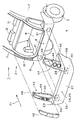
【図1】 バンパをその裏面側からみた斜視図である。
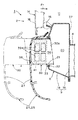
【図2】 車体後部の斜視展開図である。
【図3】 車体とバンパの側面断面図である。
【図4】 バンパの突起の正面断面図である。
【図5】 ランプ群の側面断面図である。
【符号の説明】
1 自動車
2 車体
6 車体本体
24 バンパ
25 車体構成部品
27 バンパ本体
28 バンパ側部
29 屈曲部
30 突起
36 連通路
39 開口
41 開閉弁
43 ランプ
44 ハウジング
45 ハウジング本体
46 レンズ
47 バルブ
48 ランプリフレクタ[0001]
[Technical field to which the invention belongs]
The present invention relates to a structure related to a lamp and a vehicle body component that constitutes an outer surface portion of a vehicle body of an automobile and is a bumper adjacent to each other in a direction along the outer surface of the vehicle body.
[0002]
[Prior art]
Conventionally, there is a related structure of a vehicle body component and a lamp described in Japanese Patent Laid-Open No. 5-42850.
[0003]
According to the above publication, the vehicle body includes a bumper constituting a part of the outer surface portion thereof, and a pair of left and right members constituting the other portion of the outer surface portion adjacent to the bumper in a direction along the outer surface of the vehicle body. Headlamps.
[0004]
The lamp usually includes a housing main body that supports the bulb and a lamp reflector that is plated on the inner surface of the housing main body.
[0005]
[Problems to be solved by the invention]
By the way, in the said prior art, since a bumper and a lamp | ramp are mutually shape | molded separately, there exists a problem that the number of parts of a vehicle body increases and the structure of a vehicle body becomes complicated.
[0006]
In addition, since the bumper and the lamp constitute an outer surface portion of the vehicle body, a gap generated between the both is easily visible in appearance, and this causes another problem that the appearance of the vehicle body is deteriorated. There is also a point.
[0007]
Therefore, it is conceivable to integrally form the bumper and the housing body so that the lower end portion of the lamp housing body is integrally coupled to the upper surface portion of the bumper. In this way, since the shape of the bumper and the housing body hardly change, it is considered that the above-described problems can be avoided in a state where the functions of the bumper and the lamp are not impaired.
[0008]
However, when integrally molded as described above, the housing body protrudes from the upper surface portion of the bumper to form a cantilever support structure, so that the support rigidity of the housing body with respect to the bumper becomes insufficient, and these relative dimensions are reduced. A large error may occur, that is, a large dimensional error may occur in the components of the vehicle body related to the combination of the bumper and the housing body.
[0009]
On the other hand, as described above, the lamp reflector is plated on the inner surface of the housing body. However, since the lamps are provided in a pair on the left and right sides and are separate from each other, the number of the lamps is increased. In addition, the number of work steps for performing the plating work increases, and thus the lamp forming work is complicated.
[0010]
The present invention was made paying attention to the above situation, and by reducing the number of components of the vehicle body, the configuration of the vehicle body is simplified, the appearance of the vehicle body is improved, and Even if it does in this way, it makes it a subject to ensure favorable dimensional accuracy for the said component.
[0011]
It is another object of the present invention to make it easy to mold components such as a lamp constituting a vehicle body.
[0012]
[Means for Solving the Problems]
In order to solve the above problems, the related structure of the vehicle body component of the present invention and the lamp is as follows.
[0013]
According to the first aspect of the present invention, the
[0014]
A vertically
[0015]
According to a second aspect of the invention, in addition to the first aspect of the present invention, the
[0016]
The
[0017]
According to a third aspect of the invention, in addition to the second aspect of the invention, each of the
[0018]
DETAILED DESCRIPTION OF THE INVENTION
Hereinafter, embodiments of the present invention will be described with reference to the drawings.
[0019]
In the figure,
[0020]
The
[0021]
An interior space of the
[0022]
The
[0023]
The
[0024]
The
[0025]
A resin rear bumper 24 that covers the
[0026]
The bumper 24 includes a
[0027]
On the back surface (front surface) of the
[0028]
A ring-shaped and
[0029]
An
[0030]
A
[0031]
More specifically, the
[0032]
An open /
[0033]
When the air pressure in the
[0034]
When air outside the
[0035]
In addition to the vehicle body component 25 (bumper 24) constituting a part of the outer surface of the
[0036]
More specifically, the
[0037]
Each of the
[0038]
In each of the above-mentioned
[0039]
Switch means 51 is provided that is supported by the
[0040]
When the bumper 24 is supported on the
[0041]
Next, the bumper 24 is lifted and the protruding ends of the
[0042]
Although the above is based on the illustrated example, the
[0043]
According to the above configuration, the working
[0044]
A
[0045]
For this reason, since the working
[0046]
Conventionally, a cover body for closing the
[0047]
Further, as described above, the bumper 24 which is the vehicle body component 25 is integrally formed with the
[0048]
Therefore, the number of parts of the
[0049]
In the above case, the
[0050]
For this reason, the
[0051]
Therefore, the occurrence of an error in the relative dimensions of the vehicle body component 25 (bumper 24) and the housing
[0052]
Further, as described above, each
[0053]
Therefore, the bumper 24 has a substantially U-shape that opens forward or rearward in a plan view, and each of the
[0054]
For this reason, in the injection molding, the component parts (24, 30, 45) can be molded mainly by using the front and rear molds and by releasing them in the front and rear directions. 24, 30, 45) can be easily formed.
[0055]
Further, as described above, each of the
[0056]
Here, as described above, the housing
[0057]
Therefore, compared to the conventional case where the
[0058]
【The invention's effect】
The effects of the present invention are as follows.
[0059]
The invention according to
[0060]
The bent part of the bumper and the housing of the lamp are integrally formed with each other.
[0061]
For this reason, compared with molding the bumper and the housing individually, the number of parts of the vehicle body is reduced, and the configuration of the vehicle body is simplified. Further, as described above, the bumper and the housing are integrally formed with each other, and no gap is formed between the bumper and the housing. To do.
[0062]
In the above case, the vertically long lamp housing protrudes from the upper surface of the bent portion of the bumper , and the bent portion and the housing are integrally formed with each other.
[0063]
For this reason, the housing protrudes from the upper surface portion of the bumper and has a cantilever support structure. However, since the bent portion has a rigidity higher than that of a portion extending linearly, the housing is supported by the bumper . The rigidity is sufficiently secured.
[0064]
Therefore, an error in the relative dimensions of the bumper and the housing is suppressed, and good dimensional accuracy is ensured for the components of the vehicle body related to these combinations.
[0065]
According to a second aspect of the invention, the upper Symbol lamps provided right and left, a housing body of bowl-shaped housing of each lamp is open towards the outside in the longitudinal direction of the vehicle body, outside the opening of the housing body vehicle In a car with a lens that can be opened and closed from the side,
[0066]
The bent portions and the housing bodies of the lamps corresponding to the bent portions are integrally formed with each other.
[0067]
For this reason, the bumper has a substantially U-shape that opens frontward or rearward in a plan view, and each housing body also has a hook shape that opens in the front-rear direction. The components of the vehicle body are integrally formed with each other.
[0068]
For this reason, in the injection molding, the component part can be molded mainly by using the front and rear molds and by releasing them in the front and rear directions. Therefore, the component part can be easily molded.
[0069]
According to a third aspect of the present invention, each of the lamps includes a lamp reflector that is plated on the inner surface of the housing body.
[0070]
Here, as described above, since the housing body of each lamp is integrally formed with the bumper, when trying to plate the inner surface of each housing body, for example, when the bumper is supported on the fixed side of the plating facility, Accordingly, both the housing bodies are supported on the fixed side.
[0071]
Therefore, compared to the conventional case where it is necessary to individually perform the plating operation on the housing body, the plating operation is facilitated, that is, the lamp forming operation can be easily performed.
[Brief description of the drawings]
FIG. 1 is a perspective view of a bumper as seen from the back side.
FIG. 2 is a perspective development view of a rear part of a vehicle body.
FIG. 3 is a side sectional view of a vehicle body and a bumper.
FIG. 4 is a front sectional view of a bumper protrusion.
FIG. 5 is a side sectional view of a lamp group.
[Explanation of symbols]
DESCRIPTION OF
Claims (3)
上記バンパの屈曲部の上面部から縦長形状の上記ランプのハウジングを突出させ、上記屈曲部と上記ハウジングとを互いに一体成形した自動車の車体構成部品とランプとの関連構造。A vehicle body comprising a vehicle body component constituting a part of the outer surface portion, and a lamp constituting the other portion of the outer surface portion adjacent to the vehicle body component in a direction along the outer surface of the vehicle body; The vehicle body component has a bent portion, and the vehicle body component is a bumper supported on the end of the vehicle body in the longitudinal direction of the vehicle, and the bumper extends along the outer surface of the vehicle body end along the width direction of the vehicle body. And a pair of left and right bumper side portions extending from the respective end portions of the bumper body toward the vehicle body body in the front-rear direction of the vehicle body and extending integrally along the outer surface of the vehicle body body, In the related structure of the vehicle body component part and the lamp of the automobile in which the transition part from the end part of the main body to each bumper side part is the bent part ,
A related structure of a vehicle body component and a lamp in which a vertically long lamp housing is protruded from an upper surface of a bent portion of the bumper , and the bent portion and the housing are integrally formed with each other.
上記各屈曲部とこれに対応する上記各ランプのハウジング本体とを互いに一体成形した請求項1に記載の自動車の車体構成部品とランプとの関連構造。 On SL lamp provided pair, the housing body of the bowl-shaped housing of each lamp is open towards the outside in the longitudinal direction of the vehicle body, openably closes the lens aperture of the housing body from the vehicle body outer side In a car equipped with
The related structure of a vehicle body component and a lamp according to claim 1, wherein each of the bent portions and the corresponding housing body of each lamp are integrally formed.
Priority Applications (1)
| Application Number | Priority Date | Filing Date | Title |
|---|---|---|---|
| JP37483099A JP3667584B2 (en) | 1999-12-28 | 1999-12-28 | Related structure of automotive body components and lamps |
Applications Claiming Priority (1)
| Application Number | Priority Date | Filing Date | Title |
|---|---|---|---|
| JP37483099A JP3667584B2 (en) | 1999-12-28 | 1999-12-28 | Related structure of automotive body components and lamps |
Publications (2)
| Publication Number | Publication Date |
|---|---|
| JP2001187546A JP2001187546A (en) | 2001-07-10 |
| JP3667584B2 true JP3667584B2 (en) | 2005-07-06 |
Family
ID=18504505
Family Applications (1)
| Application Number | Title | Priority Date | Filing Date |
|---|---|---|---|
| JP37483099A Expired - Fee Related JP3667584B2 (en) | 1999-12-28 | 1999-12-28 | Related structure of automotive body components and lamps |
Country Status (1)
| Country | Link |
|---|---|
| JP (1) | JP3667584B2 (en) |
Families Citing this family (2)
| Publication number | Priority date | Publication date | Assignee | Title |
|---|---|---|---|---|
| CN106494338B (en) * | 2016-12-01 | 2020-07-17 | 广东东箭汽车科技股份有限公司 | Front guard bar of pickup truck |
| EP4026680A4 (en) * | 2019-10-10 | 2023-07-05 | Resonac Corporation | Injection molded product |
-
1999
- 1999-12-28 JP JP37483099A patent/JP3667584B2/en not_active Expired - Fee Related
Also Published As
| Publication number | Publication date |
|---|---|
| JP2001187546A (en) | 2001-07-10 |
Similar Documents
| Publication | Publication Date | Title |
|---|---|---|
| JP3600880B2 (en) | Vehicle roof rack fixing device | |
| JP4038975B2 (en) | Vehicle door mirror | |
| JP6872517B2 (en) | Body front structure | |
| JP3667584B2 (en) | Related structure of automotive body components and lamps | |
| GB1570272A (en) | Motor vehicle body front apron element of polymeric material | |
| EP1905678B1 (en) | Support structure for lamp body unit | |
| US7322728B2 (en) | Mounting structure for high-mounted stop lamp | |
| JP3805693B2 (en) | instrument panel | |
| JP2000142175A (en) | Structure of combining instrument panel with console box | |
| JP3681446B2 (en) | Motorcycle cowling mating structure | |
| JP3631077B2 (en) | Device for connecting lamps in automobiles | |
| JP3692704B2 (en) | Bumper embedded vehicle lamp mounting structure | |
| JP2001187551A (en) | Support portion structure of bumper on car body of automobile | |
| KR20210060624A (en) | Vehicle body with loudspeaker module | |
| JP2001138957A (en) | Rear body structure | |
| JP7444033B2 (en) | vehicle mudguard | |
| JP3649298B2 (en) | Motorcycle taillight mounting structure | |
| JP4074798B2 (en) | Mounting structure for glove box lighting | |
| JP3840842B2 (en) | Automobile vortex horn structure | |
| JP2002075024A (en) | Mounting structure of fog lamp for automobile | |
| JPS60229837A (en) | Vehicle lamp | |
| JPH10203233A (en) | Lamp attaching structure for vehicle | |
| KR100188152B1 (en) | Aux stop lamp | |
| JP2003081162A (en) | Peripheral cover structure of tail lamp for motorcycle | |
| JP2573123Y2 (en) | Grommets for vehicle lighting |
Legal Events
| Date | Code | Title | Description |
|---|---|---|---|
| A977 | Report on retrieval |
Free format text: JAPANESE INTERMEDIATE CODE: A971007 Effective date: 20040830 |
|
| A131 | Notification of reasons for refusal |
Free format text: JAPANESE INTERMEDIATE CODE: A131 Effective date: 20040907 |
|
| A521 | Written amendment |
Free format text: JAPANESE INTERMEDIATE CODE: A523 Effective date: 20041105 |
|
| TRDD | Decision of grant or rejection written | ||
| A01 | Written decision to grant a patent or to grant a registration (utility model) |
Free format text: JAPANESE INTERMEDIATE CODE: A01 Effective date: 20050405 |
|
| A61 | First payment of annual fees (during grant procedure) |
Free format text: JAPANESE INTERMEDIATE CODE: A61 Effective date: 20050406 |
|
| R150 | Certificate of patent (=grant) or registration of utility model |
Free format text: JAPANESE INTERMEDIATE CODE: R150 |
|
| FPAY | Renewal fee payment (prs date is renewal date of database) |
Free format text: PAYMENT UNTIL: 20080415 Year of fee payment: 3 |
|
| FPAY | Renewal fee payment (prs date is renewal date of database) |
Free format text: PAYMENT UNTIL: 20100415 Year of fee payment: 5 |
|
| LAPS | Cancellation because of no payment of annual fees |