JP3665450B2 - Air conditioner outdoor unit - Google Patents
Air conditioner outdoor unit Download PDFInfo
- Publication number
- JP3665450B2 JP3665450B2 JP22798897A JP22798897A JP3665450B2 JP 3665450 B2 JP3665450 B2 JP 3665450B2 JP 22798897 A JP22798897 A JP 22798897A JP 22798897 A JP22798897 A JP 22798897A JP 3665450 B2 JP3665450 B2 JP 3665450B2
- Authority
- JP
- Japan
- Prior art keywords
- component box
- electrical component
- blower
- outdoor unit
- air conditioner
- Prior art date
- Legal status (The legal status is an assumption and is not a legal conclusion. Google has not performed a legal analysis and makes no representation as to the accuracy of the status listed.)
- Expired - Lifetime
Links
Images


Description
【0001】
【発明の属する技術分野】
この発明は、空気調和機の室外ユニットに係わり、電装品取付け構造に関するものである。
【0002】
【従来の技術】
図5は、例えば実開平5−90223号公報に示された従来の空気調和機の室外ユニットの正面図である。
図において、室外ユニット13は筐体25を含み、筐体25の中央やや左下には熱交換器17が配置され、熱交換器17の右側には冷媒ガスを圧縮する圧縮機14が配置される。また、熱交換器17の前方には、圧縮機14で圧縮された冷媒ガスから熱を取り除くプロペラファン15が配置される。
【0003】
また、プロペラファン15の上部には筐体25を上下に仕切る仕切板26が設けられ、この仕切板26の上面の電気品箱1には基板5が配置される。さらに、基板5の上面には発熱電子部品6、7が実装される。
基板5の下面には、プロペラファン15の風を受けるように放熱フィン8が取り付けられる。
【0004】
さらに、プロペラファン15と圧縮機14との間には、筐体25の下部を左右に仕切る仕切板16が設けられ、この仕切板16には基板9が取り付けられ、基板9の圧縮機14側主面には発熱電子部品11が実装される。
また、基板9のプロペラファン15側主面には、プロペラファン15の風を受けるように放熱フィン12が取り付けられている。
【0005】
室外ユニット13の熱交換器17だけでなく、発熱電子部品6、7、11もプロペラファン15により冷却される。
【0006】
【発明が解決しようとする課題】
従来の空気調和機の室外ユニットは、以上のように構成されているので、電気品箱1においては、放熱フィン8、12を冷却するためにプロペラファン15を利用しているので、放熱フィン8及び12の面積を確保して、尚かつプロペラファン15側に露出させる必要性から電気品の配置が上部と側方に分散しているため、電気品箱1の小型化が困難であった。
【0007】
この発明は、上記のような問題点を解消するためになされたもので、電気品箱の小型化を図ると共に、放熱フィンをプロペラファンにより効果的に冷却できる空気調和機の室外ユニットを提供することを目的とする。
また、放熱フィンの放熱効果を高めることを目的とする。
さらに、電気品箱内部の通風を効果的に行うと共に、通風口からの水の侵入を防止することを目的とする。
【0008】
【課題を解決するための手段】
この発明に係る空気調和機の室外ユニットは、室外ユニット本体と、本体に設けられ、送風機を有する送風機室と、本体に送風機室に隣接して設けられ、インバータ等の電気部品を有する電気品箱と、電気品箱の上面を覆うように水平に取り付けられ、電気品箱の一側面に露出させて送風機により冷却される第1の発熱部品を取り付けた第1の放熱フィンを有する第1のプリント基板と、電気品箱の背面を覆うように垂直に取り付けられ、電気品箱の背面に露出させて送風機により冷却される第2の発熱部品を取り付けた第2の放熱フィンを有する第2のプリント基板とを備えたものである。
【0009】
また、電気品箱の他側面に設けられ、電気品箱の内部空間に冷却のための外気を導入する外気導入口と、電気品箱に設けられ、第1の発熱部品と第1の放熱フィンとを冷却した外気を送風機室側に通す第1の通風口とを備えたものである。
【0010】
また、第1の遮蔽板を通風口の送風機側に設けたものである。
【0011】
また、電気品箱は一部が送風機室に突出し、その突出部を送風機の回転領域の外側四隅の一隅に配置したものである。
【0012】
また、送風機の回転領域の外側に沿うように、第1の放熱フィンの各フィンの長さを変化させて配置したものである。
【0013】
また、電気品箱の他側面に設けられ、電気品箱の内部空間に冷却のための外気を導入する外気導入口と、電気品箱の送風機側垂直面に設けられ、電気品箱の内部空気を送風機室側に抜く第2の通風口と、この第2の通風口を覆い、開口部が本体前面側を向き、開口部を送風機のベルマウス部後端より前面側に配置した第2の遮蔽板とを備えたものである。
【0014】
【発明の実施の形態】
実施の形態1.
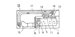
以下、この発明の実施の形態の一例を図面を参照して説明する。図1〜4はこの発明の実施の形態の一例を示す図で、図1は電装品取付構造を示す分解斜視図、図2は空気調和機の室外ユニットの平面図、図3は空気調和機の室外ユニットの正面図、図4は空気調和機の室外ユニットの要部断面図である。
【0015】
図において、1は電気品箱で、内部にリアクタ2及び端子台3を収納し、基板ホルダー(A)4により第1のプリント基板であるプリント基板(A)5を水平に保持すると共に電気品箱1に固定している。
【0016】
プリント基板(A)5には、第1の発熱部品である発熱する電子部品(A1)6および電子部品(A2)7が取り付けられており、第1の放熱フィンである放熱フィン(A)8にネジ止めにて固定される。
第2のプリント基板であるプリント基板(B)9は、基板ホルダー(B)10により垂直に電気品箱1に固定される。
【0017】
プリント基板(B)9には、第2の発熱部品である発熱する電子部品(B)11が取り付けられており、第2の放熱フィンである放熱フィン(B)12にネジ止めにて固定される。
【0018】
このように構成されたインバーター用の電気品箱1は、室外ユニット13の内部において、圧縮機14の収納された圧縮機室と、プロペラファン15の収納された送風機室とを区画する仕切板16の上部に送風機室の上部に張り出す形で収納されている。
【0019】
そして、放熱フィン(A)5は、電気品箱1の側面から送風機室側に露出し、プロペラファン15の回転域の外側の空間に位置する。
また、放熱フィン(B)9は、電気品箱1の背面側に露出し、室外ユニット13の背面にある熱交換器17と電気品箱1との間の空間に位置する。
それぞれの放熱フィン(A)5、(B)9は、送風機室側に露出しているため、プロペラファン15の回転による気流により冷却を促進される。
【0020】
また、電気品箱1の内部空間の放熱を行うため、電気品箱1右側にあるサービスパネル18に外気導入口であるルーバー19が設けられ、運転中にプロペラファン15の回転により送風機室が負圧になることによって、外気を吸い込み電気品箱1の内部を通った気流を送風機室に抜くように構成されている。
【0021】
上記のように構成された電気品において、電気品箱1の内部に置かれたリアクター2等の背面と上面を、プリント基板(A)5、プリント基板(B)9で覆うように構成することにより、電気品を集約し小型化を図ることができる。
【0022】
また、放熱フィン(A)8、放熱フィン(B)12を電気品箱1の側面と背面に配置することにより、送風機室側に露出させて取り付ける必要があるという制約を満たして、より広い面積の放熱フィンを設けることができる。
【0023】
電気品箱1内部を右側から左側に向かって外気を取り入れて冷却する場合に、プリント基板(A)5に取り付けられた発熱する電子部品(A1)6及び発熱する電子部品(A2)7と放熱フィン8との間の空間から、外気を送風機室側に抜く第1の通風口である通風口(A)20を設けることにより、放熱フィン(A)8に対して、下側においては、プロペラファン15による気流と、上面においては、電気品箱内部を通る外気の流れができるため、放熱フィン(A)8の両面を流れる気流ができることになり、放熱効果を高めることが可能となる。
【0024】
また、通風口(A)20の送風機側に第1の遮蔽板である遮蔽板21を設けることにより、降雨時にプロペラファン15から水が跳ね上げられ電気品箱1に侵入するのを防止する事ができる。
【0025】
電気品箱1の送風機室側に面する部分を、階段状に成形し、送風機室に向けて下向きに放熱フィン(A)8を設け、プロペラファン15の回転域の外側にある空間に沿った形状に一枚一枚のフィンの長さを変化させて配置している。
【0026】
送風機室側においては、プロペラファン15の回転域の外側4隅に三角形の空間が空いているため、この部分を有効に活用する事によりユニットの小型化を図ることができる。
【0027】
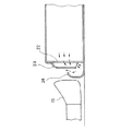
電気品箱1には、内部空気を送風機室側に抜く第2の通風口である通風口(B)22が電気品箱1の送風機側の垂直面に設けられており、この通風口を覆う第2の遮蔽板であるカバー23を外側に設けると共に、カバー23の開口部を前面側に向け、送風機のベルマウス部24後端より前面側に開口部を配置することにより、開口部からの水の侵入を防ぎ、内部の通風を効果的に行う。
【0028】
【発明の効果】
この発明に係る空気調和機の室外ユニットは、プリント基板を水平と垂直に組み合わせて配置し、放熱フィンを電気品箱の側面と背面とに設けることにより、電気品箱部品収納効率を高め、電気品箱及び室外ユニットの小型化を実現する。
【0029】
また、第1の発熱部品と第1の放熱フィンとを冷却した外気を送風機室側に通す第1の通風口を設けることにより、第1の放熱フィンの放熱効果を高める効果がある。
【0030】
また、第1の遮蔽板を通風口の送風機側に設けることにより送風機により降雨等の水が電気品箱に侵入するのを抑制する。
【0031】
また、送風機室に突出した電気品箱部分を、送風機の回転領域の外側四隅の一隅に配置することにより、室外ユニットの小型化を図ることができる。
【0032】
また、送風機の回転領域の外側に沿うように、第1の放熱フィンの各フィンの長さを変化させて配置することにより、室外ユニットの小型化を図ることができる。
【0033】
また、電気品箱の送風機側垂直面に設けられ、電気品箱の内部空気を送風機室側に抜く第2の通風口と、この第2の通風口を覆い、開口部が本体前面側を向き、開口部を送風機のベルマウス部後端より前面側に配置した第2の遮蔽板とを備えることにより、開口部からの水の侵入を防ぎ、内部の通風を効果的に行うことができる。
【図面の簡単な説明】
【図1】 この発明の実施の形態の一例を示す図で、電装品取付構造を示す分解斜視図である。
【図2】 この発明の実施の形態の一例を示す図で、空気調和機の室外ユニットの平面図である。
【図3】 この発明の実施の形態の一例を示す図で、空気調和機の室外ユニットの正面図である。
【図4】 この発明の実施の形態の一例を示す図で、空気調和機の室外ユニットの要部断面図である。
【図5】 従来の空気調和機の室外ユニットの正面図である。
【符号の説明】
1 電気品箱、2 リアクタ、3 端子台、4 基板ホルダー(A)、5 プリント基板(A)、6 発熱電子部品(A1)、7 発熱電子部品(A2)、8放熱フィン(A)、9 プリント基板(B)、10 基板ホルダー(B)、11 発熱電子部品(B)、12 放熱フィン(B)、13 室外ユニット、14圧縮機、15 プロペラファン、16 仕切板、17 熱交換器、18 サービスパネル、19 ルーバー、20 通風口(A)、21 遮蔽板、22 通風口(B)、23 カバー、24 ベルマウス。[0001]
BACKGROUND OF THE INVENTION
The present invention relates to an outdoor unit of an air conditioner, and relates to an electrical component mounting structure.
[0002]
[Prior art]
FIG. 5 is a front view of an outdoor unit of a conventional air conditioner disclosed in, for example, Japanese Utility Model Laid-Open No. 5-90223.
In the figure, the
[0003]
In addition, a
[0004]
Further, a
Further,
[0005]
Not only the
[0006]
[Problems to be solved by the invention]
Since the conventional outdoor unit of the air conditioner is configured as described above, the
[0007]
The present invention has been made to solve the above-described problems, and provides an outdoor unit of an air conditioner that can reduce the size of an electrical component box and can effectively cool a radiating fin by a propeller fan. For the purpose.
Moreover, it aims at improving the heat dissipation effect of a radiation fin.
It is another object of the present invention to effectively ventilate the interior of the electrical component box and prevent water from entering from the vent.
[0008]
[Means for Solving the Problems]
An outdoor unit of an air conditioner according to the present invention includes an outdoor unit main body, a fan chamber provided in the main body and having a fan, and an electric component box provided in the main body adjacent to the fan chamber and having electric components such as an inverter. And a first print having a first heat dissipating fin, which is mounted horizontally so as to cover the upper surface of the electrical component box, and is exposed to one side of the electrical component box and is cooled by a blower. A second print having a substrate and a second heat dissipating fin that is vertically attached so as to cover the back of the electrical component box, and is exposed to the back of the electrical component box and is cooled by a blower. And a substrate.
[0009]
Also, an outside air inlet provided on the other side surface of the electrical component box for introducing outside air for cooling into the internal space of the electrical component box, and a first heat generating component and a first radiating fin provided in the electrical component box. And a first ventilation port through which the outside air cooled is passed to the blower chamber side.
[0010]
The first shielding plate is provided on the blower side of the ventilation opening.
[0011]
Moreover, a part of the electrical component box protrudes into the blower chamber, and the protruding portion is arranged at one corner of the outer four corners of the rotation area of the blower.
[0012]
Moreover, the length of each fin of the 1st radiation fin is changed and arrange | positioned along the outer side of the rotation area | region of an air blower.
[0013]
Also, provided on the other side of the electrical component box, the outside air introduction port for introducing outside air for cooling into the interior space of the electrical component box, and the blower side vertical surface of the electrical component box, the internal air of the electrical component box A second ventilation opening that covers the second ventilation opening, covers the second ventilation opening, the opening faces the front side of the main body, and the opening is arranged on the front side from the rear end of the bell mouth part of the blower. And a shielding plate.
[0014]
DETAILED DESCRIPTION OF THE INVENTION
Hereinafter, an example of an embodiment of the present invention will be described with reference to the drawings. 1 to 4 are diagrams showing an example of an embodiment of the present invention, FIG. 1 is an exploded perspective view showing an electrical component mounting structure, FIG. 2 is a plan view of an outdoor unit of an air conditioner, and FIG. 3 is an air conditioner FIG. 4 is a cross-sectional view of a main part of the outdoor unit of the air conditioner.
[0015]
In the figure,
[0016]
The printed circuit board (A) 5 is attached with a heat generating electronic component (A1) 6 and an electronic component (A2) 7 which are first heat generating components, and a heat radiating fin (A) 8 which is a first heat radiating fin. It is fixed with screws.
A printed circuit board (B) 9 as a second printed circuit board is fixed to the
[0017]
The printed circuit board (B) 9 is attached with a heat generating electronic component (B) 11 which is a second heat generating component, and is fixed to the heat radiating fin (B) 12 which is a second heat radiating fin with screws. The
[0018]
The
[0019]
The heat radiating fins (A) 5 are exposed from the side surface of the
Further, the radiation fin (B) 9 is exposed on the back side of the
Since each of the radiating fins (A) 5 and (B) 9 is exposed to the blower chamber side, cooling is promoted by the airflow generated by the rotation of the
[0020]
In addition, a
[0021]
In the electrical product configured as described above, the back surface and the top surface of the
[0022]
In addition, by disposing the radiating fins (A) 8 and the radiating fins (B) 12 on the side surface and the back surface of the
[0023]
When the inside of the
[0024]
Further, by providing a shielding
[0025]
The part facing the blower chamber side of the
[0026]
On the blower chamber side, since the triangular spaces are vacant at the outer four corners of the rotation area of the
[0027]
The
[0028]
【The invention's effect】
The outdoor unit of the air conditioner according to the present invention is arranged by combining the printed circuit boards horizontally and vertically, and by providing the radiation fins on the side surface and the back surface of the electrical component box, thereby improving the electrical component box component storage efficiency, Realize downsizing of product boxes and outdoor units.
[0029]
Moreover, there is an effect of enhancing the heat radiation effect of the first heat radiation fins by providing the first ventilation port through which the outside air that has cooled the first heat generating component and the first heat radiation fins is passed to the blower chamber side.
[0030]
Further, by providing the first shielding plate on the air blower side of the air outlet, water such as rainfall is prevented from entering the electrical component box by the air blower.
[0031]
Moreover, the outdoor unit can be miniaturized by arranging the electrical component box portion protruding into the blower chamber at one corner of the outer four corners of the rotation area of the blower.
[0032]
Further, the outdoor unit can be reduced in size by changing the length of each fin of the first radiating fin along the outside of the rotation area of the blower.
[0033]
Also, a second ventilation port provided on the vertical side of the blower side of the electrical component box, which draws the internal air of the electrical component box to the blower chamber side, covers the second ventilation port, and the opening faces the front side of the main body By providing the second shielding plate in which the opening is disposed on the front side from the rear end of the bell mouth portion of the blower, water can be prevented from entering from the opening and the internal ventilation can be effectively performed.
[Brief description of the drawings]
FIG. 1 is a diagram showing an example of an embodiment of the present invention, and is an exploded perspective view showing an electrical component mounting structure.
FIG. 2 is a diagram showing an example of an embodiment of the present invention, and is a plan view of an outdoor unit of an air conditioner.
FIG. 3 is a diagram showing an example of an embodiment of the present invention, and is a front view of an outdoor unit of an air conditioner.
FIG. 4 is a diagram showing an example of an embodiment of the present invention, and is a cross-sectional view of a main part of an outdoor unit of an air conditioner.
FIG. 5 is a front view of an outdoor unit of a conventional air conditioner.
[Explanation of symbols]
1 Electrical component box, 2 reactor, 3 terminal block, 4 substrate holder (A), 5 printed circuit board (A), 6 heat generating electronic component (A1), 7 heat generating electronic component (A2), 8 heat dissipating fin (A), 9 Printed circuit board (B), 10 circuit board holder (B), 11 heat generating electronic component (B), 12 heat radiation fin (B), 13 outdoor unit, 14 compressor, 15 propeller fan, 16 partition plate, 17 heat exchanger, 18 Service panel, 19 louvers, 20 Ventilation hole (A), 21 Shield plate, 22 Ventilation hole (B), 23 cover, 24 bell mouth.
Claims (6)
前記本体に設けられ、送風機を有する送風機室と、
前記本体に前記送風機室に隣接して設けられ、インバータ等の電気部品を有する電気品箱と、
前記電気品箱の上面を覆うように水平に取り付けられ、前記電気品箱の一側面に露出させて前記送風機により冷却される第1の発熱部品を取り付けた第1の放熱フィンを有する第1のプリント基板と、
前記電気品箱の背面を覆うように垂直に取り付けられ、前記電気品箱の背面に露出させて前記送風機により冷却される第2の発熱部品を取り付けた第2の放熱フィンを有する第2のプリント基板と、
を備えたことを特徴とする空気調和機の室外ユニット。Outdoor unit body,
A blower chamber provided in the main body and having a blower;
An electrical component box provided in the main body adjacent to the blower chamber and having electrical components such as an inverter,
A first heat dissipating fin is mounted horizontally so as to cover the upper surface of the electric component box, and is attached to a first heat generating component that is exposed on one side of the electric component box and is cooled by the blower. A printed circuit board,
A second print having a second heat dissipating fin attached vertically to cover the back of the electrical component box and having a second heat generating component attached to the back of the electrical component box and cooled by the blower A substrate,
An air conditioner outdoor unit characterized by comprising:
前記電気品箱に設けられ、前記第1の発熱部品と前記第1の放熱フィンとを冷却した前記外気を前記送風機室側に通す第1の通風口と、
を備えたことを特徴とする請求項1記載の空気調和機の室外ユニット。An outside air inlet that is provided on the other side of the electrical component box and introduces outside air for cooling into the internal space of the electrical component box;
A first ventilation port provided in the electrical component box, for passing the outside air that has cooled the first heat-generating component and the first heat radiation fin to the blower chamber side;
The outdoor unit of an air conditioner according to claim 1, further comprising:
前記電気品箱の前記送風機側垂直面に設けられ、前記電気品箱の内部空気を前記送風機室側に抜く第2の通風口と、
この第2の通風口を覆い、開口部が前記本体前面側を向き、該開口部を前記送風機のベルマウス部後端より前面側に配置した第2の遮蔽板と、
を備えたことを特徴とする請求項1記載の空気調和機の室外ユニット。An outside air inlet that is provided on the other side of the electrical component box and introduces outside air for cooling into the internal space of the electrical component box;
A second ventilation port provided on the blower side vertical surface of the electrical component box, and for extracting the internal air of the electrical component box to the blower chamber side;
A second shielding plate that covers the second ventilation opening, the opening faces the front side of the main body, and the opening is arranged on the front side from the rear end of the bell mouth part of the blower;
The outdoor unit of an air conditioner according to claim 1, further comprising:
Priority Applications (1)
| Application Number | Priority Date | Filing Date | Title |
|---|---|---|---|
| JP22798897A JP3665450B2 (en) | 1997-08-25 | 1997-08-25 | Air conditioner outdoor unit |
Applications Claiming Priority (1)
| Application Number | Priority Date | Filing Date | Title |
|---|---|---|---|
| JP22798897A JP3665450B2 (en) | 1997-08-25 | 1997-08-25 | Air conditioner outdoor unit |
Publications (2)
| Publication Number | Publication Date |
|---|---|
| JPH1163574A JPH1163574A (en) | 1999-03-05 |
| JP3665450B2 true JP3665450B2 (en) | 2005-06-29 |
Family
ID=16869413
Family Applications (1)
| Application Number | Title | Priority Date | Filing Date |
|---|---|---|---|
| JP22798897A Expired - Lifetime JP3665450B2 (en) | 1997-08-25 | 1997-08-25 | Air conditioner outdoor unit |
Country Status (1)
| Country | Link |
|---|---|
| JP (1) | JP3665450B2 (en) |
Families Citing this family (12)
| Publication number | Priority date | Publication date | Assignee | Title |
|---|---|---|---|---|
| JP3855821B2 (en) * | 2002-03-29 | 2006-12-13 | ダイキン工業株式会社 | Separate air conditioner |
| JP5061471B2 (en) * | 2006-02-17 | 2012-10-31 | ダイキン工業株式会社 | Refrigeration unit outdoor unit |
| JP4997915B2 (en) * | 2006-10-18 | 2012-08-15 | ダイキン工業株式会社 | Air conditioner outdoor unit |
| MY169630A (en) * | 2007-04-09 | 2019-04-24 | Panasonic Corp | Electrical component box and air conditioner having same |
| JP2010091164A (en) * | 2008-10-07 | 2010-04-22 | Daikin Ind Ltd | Air conditioner |
| JP5071400B2 (en) * | 2009-02-02 | 2012-11-14 | ダイキン工業株式会社 | Electrical component module and air conditioner |
| CN103512106B (en) * | 2012-06-20 | 2017-02-08 | 珠海格力电器股份有限公司 | Module support, electric appliance box of air conditioner outdoor unit and air conditioner outdoor unit |
| WO2016189696A1 (en) * | 2015-05-27 | 2016-12-01 | 三菱電機株式会社 | Outdoor unit and protective cover |
| AU2016395713B2 (en) * | 2016-03-04 | 2019-06-20 | Mitsubishi Electric Corporation | Electrical Component module, and outdoor unit of air-conditioning apparatus |
| EP3521712A4 (en) * | 2016-09-27 | 2020-01-01 | Mitsubishi Electric Corporation | Outdoor unit for air conditioner, and air conditioner |
| WO2019176030A1 (en) * | 2018-03-14 | 2019-09-19 | 三菱電機株式会社 | Outdoor unit for hot water supplying apparatus |
| WO2020066334A1 (en) * | 2018-09-26 | 2020-04-02 | ダイキン工業株式会社 | Outdoor unit of air-conditioner |
-
1997
- 1997-08-25 JP JP22798897A patent/JP3665450B2/en not_active Expired - Lifetime
Also Published As
| Publication number | Publication date |
|---|---|
| JPH1163574A (en) | 1999-03-05 |
Similar Documents
| Publication | Publication Date | Title |
|---|---|---|
| JP3322778B2 (en) | Outdoor unit of air conditioner | |
| JP3665450B2 (en) | Air conditioner outdoor unit | |
| JP4859777B2 (en) | Outdoor unit | |
| JP2000323878A (en) | Cooling structure of electronic equipment | |
| JPH09246766A (en) | Enclosed electronic equipment case | |
| JP5446786B2 (en) | Air conditioner outdoor unit | |
| JP4748144B2 (en) | Air conditioner outdoor unit | |
| JP2580507Y2 (en) | Electronic equipment cooling device | |
| JP2004044962A (en) | Cooling device | |
| JP2003139352A (en) | Electric device unit for outdoor machine and outdoor machine for air conditioner | |
| JP2000274741A (en) | Outdoor unit of air conditioner | |
| JP3094631B2 (en) | Heat dissipation device for enclosure | |
| JPS6034839B2 (en) | Cooling structure for electrical equipment | |
| JP2002026557A (en) | Cooling structure of control panel | |
| JPH03190510A (en) | Outdoor control panel | |
| JP2000104951A (en) | Outdoor unit for air conditioner | |
| CN217495201U (en) | Three-dimensional printing equipment | |
| CN212649425U (en) | Filter shell | |
| CN219961153U (en) | Programmable multi-protocol interface converter | |
| CN214481959U (en) | Ventilative heat radiation structure of electrical control box | |
| WO2024057394A1 (en) | Outdoor unit of air conditioner | |
| JPH11330748A (en) | Heat dissipation structure of electronic equipment | |
| JPH08189672A (en) | Outdoor machine for air-conditioner | |
| JP3272503B2 (en) | Outdoor unit of air conditioner | |
| WO2021149142A1 (en) | Outdoor unit for air conditioner |
Legal Events
| Date | Code | Title | Description |
|---|---|---|---|
| A977 | Report on retrieval |
Free format text: JAPANESE INTERMEDIATE CODE: A971007 Effective date: 20041228 |
|
| TRDD | Decision of grant or rejection written | ||
| A01 | Written decision to grant a patent or to grant a registration (utility model) |
Free format text: JAPANESE INTERMEDIATE CODE: A01 Effective date: 20050329 |
|
| A61 | First payment of annual fees (during grant procedure) |
Free format text: JAPANESE INTERMEDIATE CODE: A61 Effective date: 20050401 |
|
| R150 | Certificate of patent or registration of utility model |
Free format text: JAPANESE INTERMEDIATE CODE: R150 |
|
| FPAY | Renewal fee payment (event date is renewal date of database) |
Free format text: PAYMENT UNTIL: 20080408 Year of fee payment: 3 |
|
| FPAY | Renewal fee payment (event date is renewal date of database) |
Free format text: PAYMENT UNTIL: 20090408 Year of fee payment: 4 |
|
| FPAY | Renewal fee payment (event date is renewal date of database) |
Free format text: PAYMENT UNTIL: 20100408 Year of fee payment: 5 |
|
| FPAY | Renewal fee payment (event date is renewal date of database) |
Free format text: PAYMENT UNTIL: 20100408 Year of fee payment: 5 |
|
| FPAY | Renewal fee payment (event date is renewal date of database) |
Free format text: PAYMENT UNTIL: 20110408 Year of fee payment: 6 |
|
| FPAY | Renewal fee payment (event date is renewal date of database) |
Free format text: PAYMENT UNTIL: 20120408 Year of fee payment: 7 |
|
| FPAY | Renewal fee payment (event date is renewal date of database) |
Free format text: PAYMENT UNTIL: 20120408 Year of fee payment: 7 |
|
| FPAY | Renewal fee payment (event date is renewal date of database) |
Free format text: PAYMENT UNTIL: 20130408 Year of fee payment: 8 |
|
| FPAY | Renewal fee payment (event date is renewal date of database) |
Free format text: PAYMENT UNTIL: 20130408 Year of fee payment: 8 |
|
| FPAY | Renewal fee payment (event date is renewal date of database) |
Free format text: PAYMENT UNTIL: 20140408 Year of fee payment: 9 |
|
| R250 | Receipt of annual fees |
Free format text: JAPANESE INTERMEDIATE CODE: R250 |
|
| R250 | Receipt of annual fees |
Free format text: JAPANESE INTERMEDIATE CODE: R250 |
|
| EXPY | Cancellation because of completion of term |