JP3665033B2 - Injection molding method of composite molded product and its mold - Google Patents
Injection molding method of composite molded product and its mold Download PDFInfo
- Publication number
- JP3665033B2 JP3665033B2 JP2002072018A JP2002072018A JP3665033B2 JP 3665033 B2 JP3665033 B2 JP 3665033B2 JP 2002072018 A JP2002072018 A JP 2002072018A JP 2002072018 A JP2002072018 A JP 2002072018A JP 3665033 B2 JP3665033 B2 JP 3665033B2
- Authority
- JP
- Japan
- Prior art keywords
- mold
- molding
- primary
- intermediate plate
- cavity
- Prior art date
- Legal status (The legal status is an assumption and is not a legal conclusion. Google has not performed a legal analysis and makes no representation as to the accuracy of the status listed.)
- Expired - Fee Related
Links
Images


Description
【0001】
【発明の属する技術分野】
本発明は、プラスチック射出成形において、1次成形用樹脂を金型に充填した後、金型の一部を移動して2次成形用樹脂を金型に充填させて1次成形品と2次成形品を金型内で融着させることにより、複合成形品を成形する射出成形方法及びその金型に関する。
【0002】
【従来の技術】
従来、異材複合成形品を得るためには、一度射出成形にて得た成形品を、異なる金型にインサートし、異なる樹脂を充填する成形法が主なものであったが、この成形法では、金型が2面必要となる、成形を2回行う必要がある、最初に成形した成形品の寸法変化、保管方法などに注意が必要など、効率の良い成形法であるとはいえなかった。
そのため近年では、1個の金型へ、複数の樹脂を充填することで複合成形品を得る成形法について、いくつか提案されている。また、1次成形後に金型内の入駒を移動して、1次成形品に隣接する空間を作り、その空間へ2次樹脂を充填する方法がいくつか提案されている。
【0003】
【発明が解決しようとする課題】
しかし、これらの方法は、互いの樹脂の接合面形状を複雑な形状にできない問題があった。さらには、2次樹脂を充填したときに、1次成形品とキャビティの中に樹脂が入り込み、外観を悪くするなどの問題があった。
例えば、図21に示すように、可動側キャビティ41と固定側キャビティ42およびスライドコア43によって囲まれた1次成形用キャビティ44に1次樹脂46を充填し、固化させる。その後、図22に示すようにスライドコア43を型開き方向と直交方向に進入させることで、2次成形用キャビティ45を1次樹脂46に隣接させ、2次樹脂47を充填し、1次樹脂46と2次樹脂47を金型内で融着する成形方法がある(特開平10−278076号)。
【0004】
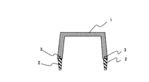
しかし、この成形方法によれば、スライドコア43は型開き方向と直交方向に移動するため、型開き方向へ凸形状となるキャビティを持つことができない。よって、例えば図2に示す1次成形品1の端面に存在する溝形状3のためのキャビティを持つことができず、接合面は単純な平面となるため、1次樹脂と2次樹脂の接触面積を広くすることができず、接合強度を高めることが困難であった。
【0005】
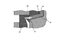
また、図23に示すように、可動側キャビティ51と固定側キャビティ52およびスライドコア53によって囲まれた1次成形用キャビティ54に1次樹脂56を充填し、固化させる。その後、図24に示すように、スライドコア53を型開き方向に後退させた後、スライドコア58を型開き方向と直行方向に進入させることで、2次成形用キャビティ55を1次樹脂56に隣接させ、2次樹脂57を充填し、1次樹脂56と2次樹脂57を金型内で融着する成形方法がある(特開平4−193513号)。
【0006】
しかし、図25に示すように、この成形法によれば、1次樹脂56は充填完了直後より収縮を開始するため、スライドコア58が移動し、1次樹脂56と2次成形用キャビティ55を隣接したときには、1次樹脂56の収縮が進行しているため、2次成形用キャビティ55との間、及び1次樹脂56と固定側キャビティ52の間に隙間が発生してしまう。そのまま2次成形を行うと、2次樹脂が1次樹脂56と固定キャビティ56の間に入り込み、外観不良を引き起こしてしまう場合がある。
【0007】
本発明は以上の如き点に鑑みて提案されるものであって、その第1の目的は、1次樹脂(1次成形品)と2次樹脂(2次成形品)との融着面積(接触面積)を拡大して複合成形品の接合強度を高めることである。更に第2の目的は、2次樹脂の充填によって発生する外観不良の問題を解消することである。
【0008】
【課題を解決するための手段】
上記目的を達成するため、請求項1に記載の発明においては、複合成形品の射出成形方法において、金型は可動側金型と固定側金型及び前記可動側金型と固定側金型の間に位置する中間プレートで構成されていると共に1次成形用キャビティは、前記中間プレートと固定側金型及び前記中間プレートに設けた入駒貫通空間から前記1次成形用キャビティ内に突出させた1次成形用入駒で構成し、1次成形は、型締めを行った後、前記1次成形用キャビティ内に1次成形用樹脂を充填して行い、次に、一旦型開きを行ったのち、前記空間内から1次成形用入駒を後退させて抜き出し、この1次成形用入駒に交替して先端に2次成形用キャビティ及びゲート並びにランナーを形成した2次成形用入駒を挿入すると共に再度型締めを行って1次成形品の一部と2次成形用入駒との間に2次成形用キャビティを形成して、この2次成形用キャビティ内に2次成形用樹脂を充填することにより2次成形を行い、次に、型開きを行って1次成形品の一部に2次成形品が一体に結合された複合成形品を取り出すことを特徴とするものである。
【0009】
更に、請求項2に記載の発明においては、請求項1に記載の発明において、1次成形後の型開き時に、中間プレートと可動側金型のみを開き、2次成形後の型開き時に中間プレートと固定側金型を開くことを特徴とするものである。
【0010】
更に、請求項3に記載の発明においては、複合成形品成形用金型において、金型は、可動側金型と固定側金型及び前記可動側金型と固定側金型の間に位置する中間プレートで構成されていること、
前記固定側金型と中間プレートの対向面には、1次成形用キャビティが夫々形成されていること、
前記固定側金型には、前記1次成形用キャビティに続く1次ランナーとこれに続くゲートが形成されていると共にこの1次ランナーとは独立して2次ランナーとキャビティ逃げが形成されていること、
前記中間プレートには、前記1次成形用キャビティに続く入駒貫通空間と、この空間を間にして予備空間が貫通して形成されていると共に前記空間に向けて2次成形ランナーとゲートが形成されていること、
前記可動側金型には、中間プレートに接する面にスライド溝が形成されていると共にこのスライド溝内にはスライドコアが挿入されていて、このスライドコアからは、前記中間プレートの空間を経由してその先端側が1次成形キャビティ内に突出する1次成形用入駒と、この入駒が前記空間内に挿入された時に、同時に予備空間内の一方に挿入されると共に先端側に2次成形用キャビティとこのキャビティに続くゲートと前記中間プレート側ランナーに接合自在の入駒側ランナーが形成された2次成形用入駒が形成されていること、を特徴とするものである。
【0011】
更に、請求項4に記載の発明においては、複合成形品成形用金型において、金型は、可動側金型と固定側金型及び前記可動側金型と固定側金型の間に位置する中間プレートで構成されていること、
前記固定側金型と中間プレートの対向面には、1次成形用キャビティが夫々形成されていること、
前記固定側金型には、前記1次成形用キャビティに続く1次ランナーとこれに続くゲートが形成されていると共にこの1次ランナーとは独立して2次ランナーとキャビティ逃げが形成されていること、
前記中間プレートには、回転入駒貫通空間が形成されていること、
前記可動側金型には、中間プレートに接する面に回転入駒保持溝が形成されていると共にこの回転入駒保持溝内には、回転自在に回転コアが組み込まれていると共にこの回転コアの正面には、型締めを行ったときにその先端側が1次成形キャビティ内に突出する1次成形用入駒が突出して形成されていると共にこの入駒から離れた位置に2次成形用キャビティとこのキャビティに続くゲートと前記中間プレート側ランナーに接合自在のランナーを形成した2次成形用入駒が突出して形成されていること、を特徴とするものである。
【0012】
更に、請求項5に記載の発明においては、請求項3又は4に記載の発明において、2次成形用入駒の先端に突形状を形成し、2次樹脂充填時に1次成形品にこの突形状を圧接させることにより、収縮により発生した隙間に2次樹脂が入り込まないように構成したこと、を特徴とするものである。
【0013】
本発明に用いる金型は、3部品構造とし、固定側金型に1次成形品用キャビティと、1次樹脂用ゲート、2次樹脂用ゲートを具備している。可動側金型にスライド(または回転)可能なスライドコア(または回転コア)を有し、スライドコア(または回転コア)に1次成形用入駒と2次成形用入駒を具備している。
スライドコア(または回転コア)に存在する1次成形用入駒には、1次成形品の端面を成すキャビティが存在し、2次樹脂との接触面積を多くすることを目的とし、部分的に凸形状を持っている。
また、3分割された構造の金型を開く時に、開く個所を制御することで、型開き量を最低限に押さえることができる。詳しくは、1次成形完了後の型開き時には、中間プレートと可動側金型の間のみを開き、スライド動作を行う。一方、2次成形完了後の型開き時には、中間プレートと固定側金型の間のみを開き、成形品の取り出しを行う。このような金型開き動作を制御することで、型開き量を低減することができ、より小さな成形機での成形を可能とするとともに、成形に要する時間を短縮することができる(請求項2)。
【0014】
また、本発明に使用される樹脂は、1次成形用に使用される樹脂として、一般の結晶性または非晶性である熱可塑性樹脂はもちろんのこと、エンジニアプラスチック熱可塑性樹脂を使用することができる。
さらに、2次成形用樹脂に使用される樹脂として、一般の結晶性または非晶性である熱可塑性樹脂はもちろんのこと、エンジニアプラスチック熱可塑性樹脂、熱可塑性エラストマーを使用することができる。
【0015】
【実施例1】
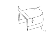
図1に示す成形品は、機構部分を保護するためのカバーであり、図2に示すものは、図1に示す成形品のA−A部断面をあらわしたものである。
このカバー1は、機構部分にゴミ等が入らないように、カバー1端面の一部にダストシール2を一体に形成して、保護カバー1は硬質樹脂、ダストシール2は軟質樹脂を使用して複合成形した例である。
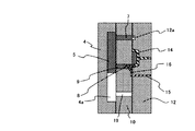
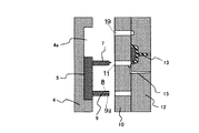
このような成形品を成形するために必要な金型の構成は、図3のように、固定側金型12、中間プレート10、可動側金型4の3プレート構造となる。
【0016】
詳しくは、金型は図3に示すように、可動側金型4にスライド溝4aを形成し、このスライド溝4aにスライドコア5が存在し、スライドコア5には、カバー1の端面を構成するためのキャビティ面6を持つ1次成形用入駒7と、シール部を構成するための2次成形用キャビティ8及び入駒ランナー9a、ゲート9bを持つ2次成形用入駒9が存在する。次に、中間プレート10には、カバー成形用のキャビティ17の一部を有すると共に、入駒貫通用空間11を設け、この入駒貫通用空間11には1次成形用入駒7および2次成形用入駒9が挿入可能である。また、前記入駒貫通空間11に続くように2次成形用ランナー10aが形成されている。さらに、中間プレート10には、1次成形用入駒7と2次成形用入駒9が型締めを行った時に1次成形用又は2次成形用入駒7、9を逃げるための予備空間19が入駒貫通用空間11を間にして2つ形成されている。
また、固定側金型12には、1次成形用ランナー13とゲート13a及びそれに連続する1次成形用キャビティ20が形成され、さらに、2次成形用ランナー15が形成されている。12aはキャビティ逃げである。
【0017】
以上説明した金型は、請求項3に記載した金型の発明に対応している。次に、この金型を用いて行う複合成形品の射出成形方法を図4〜8を用いて説明する。まず、図4に示すように、中間プレート10に存在する入駒用空間11に、スライドコアにある1次成形用入駒7へ、予備空間19には2次成形用入駒9を各挿入しながら型締めを行う。
次に、1次成形用ランナー13より、1次成形用キャビティ20へ溶融した1次樹脂14(ポリプロピレン樹脂)を充填し、冷却固化を行い、1次成形を完了する。
【0018】
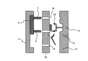
次に、図5に示すように、中間プレート10の入駒貫通用空間11内に挿入されている1次成形用入駒7を抜きながら、型開きを行う。
次に、図6に示すように、可動側金型4のスライドコア5を型開き方向と直交方向に移動し、1次成形用入駒7が存在した個所に2次成形用入駒9を存在させる。
次に、図7に示すように、中間プレート10に存在する入駒貫通用空間11に、スライドコア5側の2次成形用入駒9を挿入しながら、再び型締めを行う。
【0019】
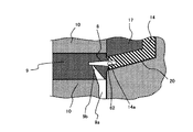
型締めを完了すると、2次成形用入駒9のシール部を構成するためのキャビティ8は、既に冷却固化を完了している1次樹脂14に接する事となる。
このとき、2次成形用入駒9の一部である1次樹脂14と接触する部分において、図26に示すようにあらかじめ1次樹脂14が収縮する寸法をみこした寸法の凸形状62を形成したことで、1次樹脂14の端面14aと2次成形用入駒9の先端の凸形状62が確実に接触している状態を作る。
【0020】
次に、2次成形成形用ランナー15→2次成形用ランナー10a→入駒側ランナー9a→ゲート9bと溶融した2次樹脂16(オレフィン系熱可塑性エラストマー)を2次成形用(ダストシール2成形用)キャビティ8へ充填する。
1次樹脂14の、2次樹脂16に接する部分は、2次樹脂16の持つ熱量により再溶融が行われ、1次樹脂14、2次樹脂16の間で溶着が行われる。
その後、1次樹脂14、2次樹脂16共に充分に冷却固化を行った後、図8に示すように金型を開き、成形品18を取り出す。
このようにして成形された成形品18は、カバー1とダストシール2が一体となって溶着されており、機構部分の保護とゴミ入り防止の2つの機能を持つことができる。更には、互いの樹脂の溶着強度は充分なものであり、また、凸形状62の作用により、樹脂のはみ出しが無く、外観上の問題がない。
【0021】
【実施例2】
本実施例2は、実施例1と同じように、図1、2に示したカバー1を成形するための金型構造であり、スライドコア5に替えて、回転コアとなし、この回転コアに1次成形用入駒26と2次成形用キャビティとを設けたものであり、請求項4に記載した金型の発明の実施例である。
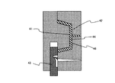
先ず、金型の構成は、図9のように、固定側金型32、中間プレート30、可動側金型24の3プレート構造となる。
【0022】
詳しくは、金型は図9に示すように、可動側金型24に形成した溝24a内に回転コア(回転入駒)25が存在し、回転コア25には、カバー1の端面を構成するための1次成形品用入駒26と、ダストシール2を構成するための2次成形用キャビティ28、2次ランナー28a、ゲート28bが存在する。さらに、中間プレート30にはカバー部キャビティ37の一部と入駒貫通用空間31を設け、この空間31には回転コア25を挿入可能とする。
また、固定側金型32には1次成形用ランナー33、ゲート33aとそれに連続する1次成形用キャビティ40を持ち、さらに、2次成形用ランナー35を持つ。更に、キャビティ逃げ32aを持つ。
【0023】
以上説明した実施例2の複合成形用金型を用いて射出成形する例を次に説明する。
まず、図10に示すように、中間プレート30に存在する入駒用空間31に、回転コア25を挿入しながら型締めを行う。
次に、1次成形用ランナー33→ゲート33aより、1次成形キャビティ37、40内に溶融した1次樹脂34(ポリプロピレン樹脂)を充填し、冷却固化を行い、1次成形を完了する。
【0024】
次に、図11に示すように、中間プレート30の入駒用空間31に挿入されている回転コア25を抜きながら、型開きを行う。
次に、図12に示すように、可動側金型24の回転コア25を回転させ、1次成形用キャビティ26が存在した位置に2次成形用キャビティ28を存在させる。
次に、図13に示すように、中間プレート30に存在する入駒用空間31に、回転コア25を挿入しながら、再び型締めを行う。
【0025】
型締めを完了すると、2次成形用入駒のシール部を構成するためのキャビティ28は、既に冷却固化を完了している1次樹脂34に接する事となる。
このとき、1次樹脂34が成形収縮により収縮する寸法をみこし、2次成形用キャビティ28の一部である、1次樹脂34と接触する部分の寸法を型締め方向に増やしておくことで、1次樹脂34の端面と2次成形用キャビティ28の一部が確実に接触している状態を作る。
【0026】
次に、2次成形成形用ランナー35より、溶融した2次樹脂36(オレフィン系熱可塑性エラストマー)をランナー28a→ゲート28bからキャビティ28へ充填する。
1次樹脂34の、2次樹脂36に接する部分は、2次樹脂36の持つ熱量により再溶融が行われ、1次樹脂34、2次樹脂36の間で溶着が行われる。
【0027】
その後、1次樹脂34、2次樹脂36共に充分に冷却固化を行った後、図14に示すように金型を開き、成形品38を取り出す。
このようにして成形された成形品38は、カバー部とシール部が一体となって溶着されており、機構部分の保護とゴミ入り防止のふたつの機能を持つことができる。更には、互いの樹脂の溶着強度は充分なものであり、樹脂のはみ出しが無く、外観上の問題がない。
【0028】
【実施例3】
本実施例3は、請求項2に記載の発明に対応するもので、型開き時に開く金型を選択することで、型開きストロークを短くした事以外は実施例1と同様の成形を行う。この例を図15から図20に示す。
使用した金型の構成は、実施例1で示したものと同じ構成を持ち、図15のように、固定側金型12、中間プレート10、可動側金型4の3プレート構造となる。
【0029】
初めに、図16に示すように型締めを行う。このとき、予め可動側金型4と中間プレート10は閉じた状態にしておく。
次に、図16に示すように、1次成形用ゲート13より、溶融した1次樹脂14(ポリプロピレン樹脂)を充填し、冷却固化を行い、1次成形を完了する。
次に、図17に示すよう、型開きを行う時に、中間プレート10と可動側金型4の間のみを開き、中間プレート10に挿入されていた1次成形用入駒7を抜く。
【0030】
次に、図18に示すよう、可動側金型4のスライドコア5を移動し、1次成形用入駒7が存在した個所に2次成形用入駒9を存在させる。
次に、図19に示すよう、再び型締めを行うとともに、中間プレート10に存在する入駒用空間11に、スライドコア5にある2次成形用入駒9を挿入する。
その後、実施例1に従い、2次成形を行う。
その後、図20に示すように、2次樹脂が冷却固化した後に型開きを行うが、このとき中間プレート10と固定側金型12の間のみを開き、成形品18を取り出す。
このような工程にて成形を行うことで、成形機の型開き量を約40%低減でき、成形機の選択幅が広がったため、より小さな成形機での成形が可能となる。
【0031】
【発明の効果】
本発明は以上のように、金型構造を固定側金型と可動側金型及びこの間に中間プレートを有する3プレートとし、固定側金型にスライドコアまたは回転コアを有し、なおかつスライドコアまたは回転コアに、1次成形用入駒(キャビティ)と2次成形用入駒(キャビティ)を有し、1次成形用入駒と2次成形用入駒を入れ替えることが可能な構造とすることで、溶融面積の拡大を図り、融着強度の高い複合成形品を得ることができる(請求項1〜4)。
また、2次成形用入駒(キャビティ)の先端に凸型部を形成することにより、1次成形樹脂の収縮に起因する外観不良の問題を解消できる(請求項5)。
【図面の簡単な説明】
【図1】複合成形品の説明図。
【図2】A−A´断面図。
【図3】実施例1における金型構造図および成形工程(型開き状態)の説明図。
【図4】実施例1における金型構造図および成形工程(1次成形)の説明図。
【図5】実施例1における金型構造図および成形工程(最型開き状態)の説明図。
【図6】実施例1における金型構造図および成形工程(スライド工程)の説明図。
【図7】実施例1における金型構造図および成形工程(2次成形)の説明図。
【図8】実施例1における金型構造図および成形工程(成形品取り出し)の説明図。
【図9】実施例2における金型構造図および成形工程(型開き状態)の説明図。
【図10】実施例2における金型構造図および成形工程(1次成形)の説明図。
【図11】実施例2における金型構造図および成形工程(最型開き状態)の説明図。
【図12】実施例2における金型構造図および成形工程(スライド工程)の説明図。
【図13】実施例2における金型構造図および成形工程(2次成形)の説明図。
【図14】実施例2における金型構造図および成形工程(成形品取り出し)の説明図。
【図15】実施例2における金型構造図および成形工程(型開き状態)の説明図。
【図16】実施例2における金型構造図および成形工程(1次成形)の説明図。
【図17】実施例2における金型構造図および成形工程(最型開き状態)の説明図。
【図18】実施例2における金型構造図および成形工程(スライド工程)の説明図。
【図19】実施例2における金型構造図および成形工程(2次成形)の説明図。
【図20】実施例2における金型構造図および成形工程(成形品取り出し)の説明図。
【図21】従来の複合成形品の成形例の説明図。
【図22】従来の複合成形品の成形例の説明図。
【図23】従来の複合成形品の成形例の説明図。
【図24】従来の複合成形品の成形例の説明図。
【図25】従来の入駒成形方法において、1次成形品が収縮して隙間が発生している例の説明図。
【図26】2次成形用入駒の先端に凸形状を形成して1次成形品の収縮に対応した例の説明図。
【符号の説明】
1 カバー部分
2 ダストシール
3 接合部の溝形状
4 可動側金型
5 スライドコア
6 1次成形用キャビティ
7 1次成形用入駒
8 2次成形用キャビティ
9 2次成形用入駒
10 中間プレート
11 入駒貫通用空間
12 固定側金型
13 1次成形用スプルー
15 2次成形用スプルー
24 可動側金型
25 回転コア
26 1次成形用キャビティ
28 2次成形用キャビティ
30 中間プレート
31 回転コア用空間
32 固定側金型
33 1次成形用スプルー
35 2次成形用スプルー[0001]
BACKGROUND OF THE INVENTION
According to the present invention, in plastic injection molding, after filling a mold with a primary molding resin, a part of the mold is moved to fill the mold with a secondary molding resin. The present invention relates to an injection molding method for molding a composite molded product by fusing a molded product in a mold and the mold.
[0002]
[Prior art]
Conventionally, in order to obtain a dissimilar composite molded product, a molding method in which a molded product once obtained by injection molding is inserted into a different mold and filled with a different resin has been the main method. , Two molds are required, it is necessary to perform molding twice, dimensional change of the molded product that was molded first, and attention to storage methods, etc., it was not an efficient molding method .
Therefore, in recent years, several methods have been proposed for obtaining a composite molded product by filling a single mold with a plurality of resins. In addition, several methods have been proposed in which the entrance into the mold is moved after the primary molding to create a space adjacent to the primary molded product and the space is filled with the secondary resin.
[0003]
[Problems to be solved by the invention]
However, these methods have a problem that the shape of the joint surfaces of the resins cannot be made complicated. Furthermore, when the secondary resin is filled, there is a problem that the resin enters the primary molded product and the cavity to deteriorate the appearance.
For example, as shown in FIG. 21, a
[0004]
However, according to this molding method, the
[0005]
Further, as shown in FIG. 23, a
[0006]
However, as shown in FIG. 25, according to this molding method, the
[0007]
The present invention is proposed in view of the above points. The first object of the present invention is to provide a fusion area between a primary resin (primary molded product) and a secondary resin (secondary molded product) ( It is to increase the bonding strength of the composite molded product by expanding the contact area. Furthermore, the second object is to eliminate the problem of poor appearance caused by filling with the secondary resin.
[0008]
[Means for Solving the Problems]
In order to achieve the above object, according to the first aspect of the present invention, in the injection molding method of a composite molded product, the mold is composed of a movable side mold and a fixed side mold, and the movable side mold and the fixed side mold. The primary molding cavity is composed of an intermediate plate positioned between the intermediate plate, the fixed mold and the inter-piece through space provided in the intermediate plate, and protrudes into the primary molding cavity. It is composed of a primary molding entrance, and after the mold is clamped, the primary molding cavity is filled with the primary molding resin, and then the mold is opened once. After that, the primary molding entrance piece is retracted and extracted from the space, and the secondary molding entrance piece having the secondary molding cavity, gate, and runner formed at the tip is replaced with the primary molding entrance piece. Inserted and clamped again for primary molding Secondary molding is performed by forming a secondary molding cavity between a part of the mold and the secondary molding entrance, and filling the secondary molding cavity with the secondary molding resin. The mold is opened, and a composite molded product in which the secondary molded product is integrally bonded to a part of the primary molded product is taken out.
[0009]
Further, in the invention described in
[0010]
Furthermore, in the invention described in claim 3, in the mold for molding a composite molded product, the mold is located between the movable side mold and the fixed side mold and between the movable side mold and the fixed side mold. Consist of an intermediate plate,
Primary molding cavities are respectively formed on opposing surfaces of the stationary mold and the intermediate plate;
A primary runner that follows the primary molding cavity and a gate that follows the primary runner are formed in the fixed mold, and a secondary runner and cavity clearance are formed independently of the primary runner. about,
The intermediate plate is formed with an entrance-penetrating space following the primary molding cavity and a preliminary space penetrating the space, and a secondary molding runner and a gate are formed toward the space. is being done,
The movable mold has a slide groove formed on a surface in contact with the intermediate plate, and a slide core is inserted into the slide groove. The slide core passes through the space of the intermediate plate. A primary forming entrance piece whose tip side protrudes into the primary forming cavity, and when this entrance piece is inserted into the space, it is simultaneously inserted into one of the preliminary spaces and at the front end side is secondary formed. A secondary forming entrance frame is formed, in which an entrance side runner that can be joined to the cavity, a gate following the cavity, and the intermediate plate side runner is formed.
[0011]
Furthermore, in the invention according to
Primary molding cavities are respectively formed on opposing surfaces of the stationary mold and the intermediate plate;
A primary runner that follows the primary molding cavity and a gate that follows the primary runner are formed in the fixed mold, and a secondary runner and cavity clearance are formed independently of the primary runner. about,
The intermediate plate is formed with a rotary entrance through space,
The movable mold has a rotary frame holding groove formed on the surface in contact with the intermediate plate, and a rotary core is rotatably incorporated in the rotary frame holding groove. On the front side, there is formed a primary molding entrance piece that protrudes into the primary molding cavity when the mold is clamped, and a secondary molding cavity is provided at a position away from the entrance piece. A secondary forming entrance frame is formed in which a gate that follows the cavity and a runner that can be joined to the intermediate plate side runner are formed to protrude.
[0012]
Furthermore, in the invention described in
[0013]
The mold used in the present invention has a three-part structure, and a fixed mold has a cavity for a primary molded product, a gate for a primary resin, and a gate for a secondary resin. The movable mold has a slide core (or rotating core) that can slide (or rotate), and the slide core (or rotating core) includes a primary molding entrance and a secondary molding entrance.
The primary molding entrance piece present in the slide core (or rotating core) has a cavity that forms the end face of the primary molded product, and is intended to increase the contact area with the secondary resin. Has a convex shape.
In addition, when opening the mold having the structure divided into three, the opening amount can be minimized by controlling the opening position. Specifically, when the mold is opened after the completion of the primary molding, only the intermediate plate and the movable mold are opened, and the sliding operation is performed. On the other hand, at the time of mold opening after the completion of secondary molding, only the intermediate plate and the fixed side mold are opened, and the molded product is taken out. By controlling such a mold opening operation, the amount of mold opening can be reduced, molding with a smaller molding machine can be performed, and time required for molding can be shortened. ).
[0014]
The resin used in the present invention may be engineer plastic thermoplastic resin as well as general crystalline or amorphous thermoplastic resin as resin used for primary molding. it can.
Further, as the resin used for the secondary molding resin, not only general crystalline or amorphous thermoplastic resins, but also engineer plastic thermoplastic resins and thermoplastic elastomers can be used.
[0015]
[Example 1]
The molded product shown in FIG. 1 is a cover for protecting the mechanism portion, and the one shown in FIG. 2 shows a cross section of the AA portion of the molded product shown in FIG.
The cover 1 is formed by integrally forming a
As shown in FIG. 3, the mold configuration necessary for molding such a molded product is a three-plate structure of a fixed
[0016]
Specifically, as shown in FIG. 3, the mold has a
The fixed
[0017]
The mold described above corresponds to the mold invention described in claim 3. Next, the injection molding method of the composite molded product performed using this metal mold | die is demonstrated using FIGS. First, as shown in FIG. 4, the secondary
Next, the molten primary resin 14 (polypropylene resin) is filled into the
[0018]
Next, as shown in FIG. 5, the mold opening is performed while removing the primary forming
Next, as shown in FIG. 6, the
Next, as shown in FIG. 7, the mold is clamped again while inserting the
[0019]
When the mold clamping is completed, the
At this time, a
[0020]
Next,
The portion of the
Thereafter, both the
The molded
[0021]
[Example 2]
As in the first embodiment, the second embodiment is a mold structure for molding the cover 1 shown in FIGS. 1 and 2. Instead of the
First, as shown in FIG. 9, the mold has a three-plate structure including a fixed
[0022]
Specifically, as shown in FIG. 9, the mold has a rotating core (rotating frame) 25 in a
The fixed-
[0023]
Next, an example of injection molding using the composite molding die of Example 2 described above will be described.
First, as shown in FIG. 10, mold clamping is performed while inserting the
Next, the molten primary resin 34 (polypropylene resin) is filled into the
[0024]
Next, as shown in FIG. 11, the mold opening is performed while removing the
Next, as shown in FIG. 12, the
Next, as shown in FIG. 13, the mold clamping is performed again while the
[0025]
When the mold clamping is completed, the
At this time, the dimension in which the
[0026]
Next, the melted secondary resin 36 (olefin-based thermoplastic elastomer) is filled into the
A portion of the
[0027]
Thereafter, both the
The molded
[0028]
[Example 3]
The third embodiment corresponds to the invention described in
The used mold has the same configuration as that shown in the first embodiment, and has a three-plate structure including a fixed
[0029]
First, mold clamping is performed as shown in FIG. At this time, the
Next, as shown in FIG. 16, the molten primary resin 14 (polypropylene resin) is filled from the
Next, as shown in FIG. 17, when performing mold opening, only the
[0030]
Next, as shown in FIG. 18, the
Next, as shown in FIG. 19, the mold clamping is performed again, and the secondary forming
Thereafter, secondary molding is performed according to Example 1.
Thereafter, as shown in FIG. 20, the mold is opened after the secondary resin is cooled and solidified. At this time, only the space between the
By performing the molding in such a process, the mold opening amount of the molding machine can be reduced by about 40%, and the selection range of the molding machine is expanded, so that molding with a smaller molding machine becomes possible.
[0031]
【The invention's effect】
In the present invention, as described above, the mold structure is a fixed plate, a movable plate, and three plates having an intermediate plate therebetween, the fixed plate has a slide core or a rotating core, and the slide core or The rotary core has a primary molding entrance (cavity) and a secondary molding entrance (cavity), and the primary molding entrance and the secondary molding entrance can be interchanged. Thus, it is possible to obtain a composite molded product having a high fusion strength by enlarging the melted area (claims 1 to 4).
Further, by forming a convex part at the tip of the secondary molding entrance (cavity), the problem of poor appearance due to shrinkage of the primary molding resin can be solved.
[Brief description of the drawings]
FIG. 1 is an explanatory diagram of a composite molded product.
FIG. 2 is a cross-sectional view taken along line AA ′.
3 is a diagram illustrating a mold structure and a molding process (mold opening state) in Example 1. FIG.
FIG. 4 is a diagram illustrating a mold structure and a molding process (primary molding) in Example 1.
FIG. 5 is an explanatory diagram of a mold structure diagram and a molding process (most mold open state) in the first embodiment.
FIG. 6 is an explanatory diagram of a mold structure diagram and a molding process (sliding process) in the first embodiment.
7 is a diagram illustrating a mold structure and a molding process (secondary molding) in Example 1. FIG.
FIG. 8 is an explanatory diagram of a mold structure diagram and a molding process (molded product removal) in the first embodiment.
FIG. 9 is an explanatory diagram of a mold structure diagram and a molding process (mold opening state) in the second embodiment.
FIG. 10 is an explanatory diagram of a mold structure diagram and a molding process (primary molding) in Example 2.
FIG. 11 is an explanatory diagram of a mold structure diagram and a molding step (most mold open state) in the second embodiment.
12 is a diagram illustrating a mold structure and a molding process (slide process) in Example 2. FIG.
13 is a diagram illustrating a mold structure and a molding process (secondary molding) in Example 2. FIG.
FIG. 14 is an explanatory diagram of a mold structure diagram and a molding process (molded product removal) in Example 2.
FIG. 15 is an explanatory diagram of a mold structure diagram and a molding process (mold opening state) in the second embodiment.
16 is a diagram illustrating a mold structure and a molding process (primary molding) in Example 2. FIG.
FIG. 17 is an explanatory diagram of a mold structure diagram and a molding process (most mold open state) in the second embodiment.
18 is a diagram illustrating a mold structure and a molding process (sliding process) in Example 2. FIG.
FIG. 19 is an explanatory diagram of a mold structure diagram and a molding step (secondary molding) in Example 2.
FIG. 20 is an explanatory diagram of a mold structure diagram and a molding step (molded product removal) in Example 2.
FIG. 21 is an explanatory view of a molding example of a conventional composite molded product.
FIG. 22 is an explanatory view of a molding example of a conventional composite molded product.
FIG. 23 is an explanatory view of a molding example of a conventional composite molded product.
FIG. 24 is an explanatory view of a molding example of a conventional composite molded product.
FIG. 25 is an explanatory diagram of an example in which a gap is generated due to shrinkage of a primary molded product in a conventional frame forming method.
FIG. 26 is an explanatory diagram of an example corresponding to the shrinkage of the primary molded product by forming a convex shape at the tip of the secondary molding entrance.
[Explanation of symbols]
DESCRIPTION OF SYMBOLS 1
Claims (5)
前記固定側金型と中間プレートの対向面には、1次成形用キャビティが夫々形成されていること、
前記固定側金型には、前記1次成形用キャビティに続く1次ランナーとこれに続くゲートが形成されていると共にこの1次ランナーとは独立して2次ランナーとキャビティ逃げが形成されていること、
前記中間プレートには、前記1次成形用キャビティに続く入駒貫通空間と、この空間を間にして予備空間が貫通して形成されていると共に前記空間に向けて2次成形ランナーとゲートが形成されていること、
前記可動側金型には、中間プレートに接する面にスライド溝が形成されていると共にこのスライド溝内にはスライドコアが挿入されていて、このスライドコアからは、前記中間プレートの空間を経由してその先端側が1次成形キャビティ内に突出する1次成形用入駒と、この入駒が前記空間内に挿入された時に、同時に予備空間内の一方に挿入されると共に先端側に2次成形用キャビティとこのキャビティに続くゲートと前記中間プレート側ランナーに接合自在の入駒側ランナーが形成された2次成形用入駒が形成されていること、を特徴とする複合成形品成形用金型。The mold is composed of a movable mold and a fixed mold, and an intermediate plate positioned between the movable mold and the fixed mold,
Primary molding cavities are respectively formed on opposing surfaces of the stationary mold and the intermediate plate;
A primary runner that follows the primary molding cavity and a gate that follows the primary runner are formed in the fixed mold, and a secondary runner and cavity clearance are formed independently of the primary runner. about,
The intermediate plate is formed with an entrance-penetrating space following the primary molding cavity and a preliminary space penetrating the space, and a secondary molding runner and a gate are formed toward the space. is being done,
The movable mold has a slide groove formed on a surface in contact with the intermediate plate, and a slide core is inserted into the slide groove. The slide core passes through the space of the intermediate plate. A primary forming entrance piece whose tip side protrudes into the primary forming cavity, and when this entrance piece is inserted into the space, it is simultaneously inserted into one of the preliminary spaces and at the front end side is secondary formed. A molding die for forming a composite molded product, characterized in that a secondary molding entrance frame is formed in which an entrance side runner which can be joined to the intermediate plate side runner is formed. .
前記固定側金型と中間プレートの対向面には、1次成形用キャビティが夫々形成されていること、
前記固定側金型には、前記1次成形用キャビティに続く1次ランナーとこれに続くゲートが形成されていると共にこの1次ランナーとは独立して2次ランナーとキャビティ逃げが形成されていること、
前記中間プレートには、回転入駒貫通空間が形成されていること、
前記可動側金型には、中間プレートに接する面に回転入駒保持溝が形成されていると共にこの回転入駒保持溝内には、回転自在に回転コアが組み込まれていると共にこの回転コアの正面には、型締めを行ったときにその先端側が1次成形キャビティ内に突出する1次成形用入駒が突出して形成されていると共にこの入駒から離れた位置に2次成形用キャビティとこのキャビティに続くゲートと前記中間プレート側ランナーに接合自在のランナーを形成した2次成形用入駒が突出して形成されていること、を特徴とする複合成形品成形用金型。The mold is composed of a movable mold and a fixed mold, and an intermediate plate positioned between the movable mold and the fixed mold,
Primary molding cavities are respectively formed on opposing surfaces of the fixed mold and the intermediate plate;
The fixed die has a primary runner following the primary molding cavity and a gate following the primary runner, and a secondary runner and cavity relief formed independently of the primary runner. about,
The intermediate plate is formed with a rotary entrance through space,
The movable mold has a rotary frame holding groove formed on the surface in contact with the intermediate plate, and a rotary core is rotatably incorporated in the rotary frame holding groove. On the front side, there is formed a primary molding entrance piece whose front end protrudes into the primary molding cavity when mold clamping is performed, and a secondary molding cavity is provided at a position away from the entrance piece. A mold for molding a composite molded product, characterized in that a secondary molding entrance is formed so that a runner that can be joined to a gate following the cavity and the intermediate plate side runner is formed.
Priority Applications (1)
| Application Number | Priority Date | Filing Date | Title |
|---|---|---|---|
| JP2002072018A JP3665033B2 (en) | 2002-03-15 | 2002-03-15 | Injection molding method of composite molded product and its mold |
Applications Claiming Priority (1)
| Application Number | Priority Date | Filing Date | Title |
|---|---|---|---|
| JP2002072018A JP3665033B2 (en) | 2002-03-15 | 2002-03-15 | Injection molding method of composite molded product and its mold |
Publications (2)
| Publication Number | Publication Date |
|---|---|
| JP2003266475A JP2003266475A (en) | 2003-09-24 |
| JP3665033B2 true JP3665033B2 (en) | 2005-06-29 |
Family
ID=29202130
Family Applications (1)
| Application Number | Title | Priority Date | Filing Date |
|---|---|---|---|
| JP2002072018A Expired - Fee Related JP3665033B2 (en) | 2002-03-15 | 2002-03-15 | Injection molding method of composite molded product and its mold |
Country Status (1)
| Country | Link |
|---|---|
| JP (1) | JP3665033B2 (en) |
Families Citing this family (6)
| Publication number | Priority date | Publication date | Assignee | Title |
|---|---|---|---|---|
| JP2009143015A (en) * | 2007-12-11 | 2009-07-02 | Denso Corp | Mold device |
| JP4513892B2 (en) | 2008-04-11 | 2010-07-28 | 株式会社デンソー | Manufacturing method of valve unit |
| KR100958506B1 (en) * | 2008-10-21 | 2010-05-26 | (주)새한포리머 | A mold device and a method of mloding a product using the same |
| JP2019171817A (en) * | 2018-03-29 | 2019-10-10 | トヨタ自動車株式会社 | Mold for molding resin |
| CN109435146B (en) * | 2018-12-31 | 2023-04-25 | 欣灵电气股份有限公司 | Photoelectric switch and production process thereof and corresponding production die |
| JP7063847B2 (en) * | 2019-05-30 | 2022-05-09 | しげる工業株式会社 | Two-color molding method and epidermis with pseudo-stitching |
-
2002
- 2002-03-15 JP JP2002072018A patent/JP3665033B2/en not_active Expired - Fee Related
Also Published As
| Publication number | Publication date |
|---|---|
| JP2003266475A (en) | 2003-09-24 |
Similar Documents
| Publication | Publication Date | Title |
|---|---|---|
| JP2004001424A (en) | Injection molding method, injection mold, resin molded product and insert resin part | |
| JP3665033B2 (en) | Injection molding method of composite molded product and its mold | |
| JP5422307B2 (en) | Two-color injection molding method for resin windows | |
| JP2006192836A (en) | Manufacturing method of product by insert molding | |
| JP6138863B2 (en) | Injection molding method and injection molding apparatus | |
| JP2001205681A (en) | Mold for molding hollow product and method for molding | |
| JP2701681B2 (en) | Method for producing resin molded product and molding die apparatus | |
| JPH0643083B2 (en) | Gate cutting method | |
| JP3203870B2 (en) | Method of manufacturing resin products | |
| JPH0834031A (en) | Mold for molding hollow molded product | |
| JP4035000B2 (en) | Mold equipment | |
| JP2534876B2 (en) | Manufacturing method of tape cartridge | |
| JPH10264202A (en) | Production of composite synthetic resin molded product | |
| JP2596660B2 (en) | Joint structure of bumper reinforcement | |
| JP4037279B2 (en) | INJECTION MOLDING METHOD AND MOLDING MOLD THEREOF | |
| JPH10323865A (en) | Disk molding die | |
| JPH03142207A (en) | Injection molding method | |
| JP2629510B2 (en) | Manufacturing method for long molded products | |
| JP3630910B2 (en) | Manufacturing method of cartridge case | |
| JP3097906U (en) | Injection mold for composite molding | |
| JP3197845B2 (en) | Core of sun visor for automobile and mold device for molding the core | |
| JP2003039491A (en) | Mold assembly for injection-molding and injection- molding method using this mold | |
| JP3903026B2 (en) | Vertical injection molding machine for insert composite molding. | |
| JP2004345129A (en) | Injection mold for use in composite molding | |
| JP3920808B2 (en) | Mold for composite molding |
Legal Events
| Date | Code | Title | Description |
|---|---|---|---|
| A977 | Report on retrieval |
Free format text: JAPANESE INTERMEDIATE CODE: A971007 Effective date: 20050210 |
|
| TRDD | Decision of grant or rejection written | ||
| A01 | Written decision to grant a patent or to grant a registration (utility model) |
Free format text: JAPANESE INTERMEDIATE CODE: A01 Effective date: 20050303 |
|
| A61 | First payment of annual fees (during grant procedure) |
Free format text: JAPANESE INTERMEDIATE CODE: A61 Effective date: 20050330 |
|
| R150 | Certificate of patent or registration of utility model |
Free format text: JAPANESE INTERMEDIATE CODE: R150 |
|
| LAPS | Cancellation because of no payment of annual fees |