JP3630910B2 - Manufacturing method of cartridge case - Google Patents
Manufacturing method of cartridge case Download PDFInfo
- Publication number
- JP3630910B2 JP3630910B2 JP07452597A JP7452597A JP3630910B2 JP 3630910 B2 JP3630910 B2 JP 3630910B2 JP 07452597 A JP07452597 A JP 07452597A JP 7452597 A JP7452597 A JP 7452597A JP 3630910 B2 JP3630910 B2 JP 3630910B2
- Authority
- JP
- Japan
- Prior art keywords
- molding
- wall
- slide core
- space
- primary
- Prior art date
- Legal status (The legal status is an assumption and is not a legal conclusion. Google has not performed a legal analysis and makes no representation as to the accuracy of the status listed.)
- Expired - Fee Related
Links
Images


Landscapes
- Moulds For Moulding Plastics Or The Like (AREA)
Description
【0001】
【発明の属する技術分野】
本発明は、ディスクカートリッジやテープカートリッジ等のカートリッジケースにおいて、ケース周壁の一部が異質のプラスチック材で層状に形成してあるカートリッジケースの製造方法に関する。
【0002】
【従来の技術】
例えばケース周壁の一部に透明窓を一体成形したカートリッジケースが、特開平4−258861号公報に公知である。特開平5−109228号公報には、いわゆる二色成形法によって一次成形したケース壁面と二次成形した壁面とで、ケース周壁の一部を内外二層に形成したカートリッジケースが公知である。
【0003】
【発明が解決しようとする課題】
二色成形法は、ケース周壁の厚み寸法が十分に大きいと、問題なく成形を行える。しかし、ケース周壁の厚み寸法が小さくなるに従って、キャビティ内部において溶融樹脂の充填不良を生じ、ヒケ等の成形不良を生じる。プラスチック素材の流動性にもよるが、例えばケース周壁の全厚が1.2mm以下になると、一次成形壁と二次成形壁の厚みを均等にしたとしても、キャビティにおける樹脂の流動隙間は0.6mmしかないので、一次および二次成形のいずれの場合にも充填不良を生じる。いずれか一方の壁厚みを増すと、その壁の成形は適正に行えるが、他方の成形はさらに困難化する。
【0004】
溶融樹脂の流動性を改善し、あるいは射出圧を高めると、溶融樹脂の充填をより確実に行える。しかし、狭い流動隙間に無理に樹脂充填を行うので、ウェルドラインを生じる等の新たな不具合を避けられず、成形した壁面の強度が十分に得られない。射出圧が高い分だけ金型の損耗度も高くなる。
【0005】
本発明の目的は、ケース周壁の厚み寸法が小さく設定してある場合にも、その一部に他とは異なるプラスチック材を層状に形成できるカートリッジケースの製造方法を提供することにある。
本発明の目的は、射出圧を高くする必要もなく、異質の成形壁が内外に重なるケース周壁を確実に成形でき、層状のケース周壁の機械的強度も十分に確保できるカートリッジケースの製造方法を提供することにある。
本発明の目的は、ケース周壁の厚み寸法が、1.2mm前後と小さく設定してある場合でも、一次成形壁と二次成形壁とを確実に層状に形成できるカートリッジケースの製造方法を提供することにある。
【0006】
【課題を解決するための手段】
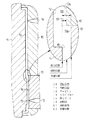
本発明は、ケース周壁1の一部に、図4に示すごとく一次成形壁4とこれより薄い二次成形壁5とが内外に重なる多層壁部6を有するカートリッジケースを対象とする。カートリッジケースを射出成形する金型のキャビティ12内には、図1に示すごとく二次成形壁5の成形空間S1を占めるスライドコア13を設ける。スライドコア13は、成形空間S1を占める進出位置と、成形空間S1から後退する成形位置と、成形位置からさらに後退して成形空間S1を含む充填空間S2を形成する充填位置とに変位できる。かくして、まず図2に示すごとくスライドコア13が進出位置に位置する状態で一次成形壁4を成形する。一次成形壁4が固化したのち、スライドコア13を進出位置から充填位置まで後退させて、二次成形用の溶融樹脂を充填空間S2へ充填する。この後に、スライドコア13を充填位置から成形位置へ進出させて、二次成形壁5を成形する。
【0007】
一次成形壁4を成形する際には、スライドコア13がキャビティ12内に進出して二次成形壁5用の成形空間S1を占めている。この状態では、多層壁部6における一次成形壁4を形成するための空間の流動隙間は、樹脂流動を確実化できる厚みに設定してあるので、一次成形壁4を支障なく成形できる。二次成形壁5を成形する際には、スライドコア13を充填位置まで後退させて、十分な流動隙間を備えた充填空間S2に溶融樹脂を充填する。この後に、スライドコア13を成形位置まで進出させて、充填空間S2内の溶融樹脂を強制的に成形空間S1側へ流動させる。このコア移動によって、成形空間S1内の樹脂は加圧されて隅々まで確実に行き渡る。従って、二次成形壁5の厚み寸法が小さい場合にも、その成形を支障なく行える。
【0008】
十分な流動隙間を有する状態で一次成形および二次成形をそれぞれ行うので、射出圧を高くする必要もなく、容易に成形を行うことができる。射出成形用金型の損耗も抑止できる。二次成形壁5は、射出圧に加えてスライドコア13による加圧力を受けて樹脂密度が高められるので、二次成形壁5にヒケ等の成形歪を生じるのを防止し、その機械的強度が向上する。
【0009】
具体的には、スライドコア13の内部に、二次成形用の溶融樹脂を供給する第2ゲート15を設けてあり、第2ゲート15から二次成形用の溶融樹脂を充填空間S2内へ供給したのち、射出圧を維持した状態のままでスライドコア13を成形位置へ進出させて、二次成形壁5を成形する。このように、スライドコア13の内部に第2ゲート15を設け、射出圧を維持した状態のままでスライドコア13を成形位置へ進出すると、成形空間S1に常時射出圧を作用させ続けることができるので、溶融樹脂の充填を確実化できる。
【0010】
多層壁部6の全厚を1.2mm前後に設定する場合には、多層壁部6における一次成形壁4の厚み寸法を0.8mm前後に設定し、充填空間S2の厚さ寸法を0.8mm前後に設定する。多層壁部6における一次成形壁4の厚み寸法を0.8mm前後に設定すると、スライドコア13とこれに対向するキャビティ12の周壁との対向隙間を十分に確保して、一次成形壁4を成形する時の樹脂流動を確実化できる。二次成形壁5の成形空間S1の厚さ寸法は0.4mmとなるが、成形空間S1を含む充填空間S2の厚さ寸法を、一次成形壁4のそれと同じ0.8mmに設定するので、この場合の樹脂流動も確実に行える。さらに充填空間S2内の樹脂の約半分を成形空間S1の側へ強制流動させるので、樹脂密度を高度化できる。
【0011】
【0012】
【実施例】
図1および図2は本発明に係るカートリッジケースの製造方法の実施例を示す。図3および図4には本発明の製造方法によって形成したカートリッジケースを示す。このカートリッジケースは、ミニディスク(ディスクカートリッジ)の上ハーフを示しており、主面壁(ケース周壁)1の右側中央に信号読書用の開口2を形成し、開口2に隣接する主面壁1の左半側に、ディスクの回動状態を視認するための窓3が扇形に設けてある。カートリッジケースは防振性に優れたプラスチック材、例えばフィラーを配合したポリカーボネート複合樹脂等を素材にして一次成形によって形成し、窓3は透明なプラスチック材、例えばポリカーボネート等を素材にして二次成形によって形成する。
【0013】
窓3を含む二次成形壁5は、窓3の周縁部において一次成形壁4と内外に重なって多層壁部6を形成している。多層壁部6の全厚寸法は、主面壁1の最大厚み寸法に一致して1.2mmに設定してあり、多層壁部6における一次成形壁4の厚み寸法は0.8mm、二次成形壁5の厚み寸法は0.4mmである。
【0014】
図1はカートリッジケースを射出成形するための金型を示す。この金型は、固定金型10と可動金型11とを備えていて、両型10・11間にカートリッジケースを成形するためのキャビティ12を有する。固定金型10側には、二次成形壁5を成形するためのスライドコア13と、一次成形用の溶融樹脂をキャビティ12内へ注入するための第1ゲート14とが設けてある。
【0015】
スライドコア13は、その端部がキャビティ12内へ突出して二次成形壁5用の成形空間S1を占める進出位置と、進出位置から固定金型10側へ後退して成形空間S1を開放する成形位置と、成形位置からさらに固定金型10側へ後退して、成形空間S1を含んでこれより大きな充填空間S2を形成する充填位置とに変位できる。スライドコア13が成形位置にあるとき、スライドコア13の突端面13aと固定金型10の内端面10aとは、面一状になっている。進出位置から成形位置までのスライドコア13の後退ストロークは0.4mmであり、成形位置から充填位置までの後退ストロークは0.4mmである。つまり、充填空間S2の厚さ寸法は0.8mmであり、一次成形壁4を形成する際のキャビティ12の厚さ寸法に一致している。
【0016】
成形空間S1に二次成形用の溶融樹脂を注入するために、スライドコア13の内部には第2ゲート15を設ける。スライドコア13の突端面と対向する可動金型11側の内面には突壁面16を設ける。この突壁面16は多層壁部6において一次成形壁4に開口を形成するために設けてあり、二次成形壁5のうち該開口と対応する殆どの部分が窓3となる。突壁面16はスライドコア13が進出位置へ進出にあるとき、スライドコア13の突端面13aに接当して第2ゲート15のゲート口17を塞ぐ。
【0017】
カートリッジケースは上記の金型を用いて図2に示す手順で成形される。
(1) 図2(a)において固定金型10に可動金型11を接合して型締めし、スライドコア13を進出位置にセットする。
(2) 図2(b)において一次成形用の溶融樹脂を第1ゲート14からキャビティ12内へ充填して一次成形壁4を成形する。
(3) 一次成形壁4が固化したのち、図2(c)に示すようにスライドコア13を充填位置まで後退させ、二次成形用の透明の溶融樹脂を第2ゲート15から充填空間S2内へ注入し充填する。
(4) 次に射出圧を維持した状態のままで、図2(d)に示すようにスライドコア13を成形位置へ進出させ、充填空間S2内の約半分の溶融樹脂を成形空間S1側へ強制的に流動させる。
(5) 上記の状態で両金型10・11を冷却して、成形空間S1に充填された樹脂を固化したのち、型開きしてカートリッジケースを取り出す。
【0018】
本発明はディスクカートリッジの下ハーフやテープカートリッジの上ハーフおよび下ハーフを成形する場合にも同様に適用できる。
【0019】
【発明の効果】
本発明では、一次成形壁4を成形したのち、スライドコア13を充填位置まで後退させて、二次成形用の溶融樹脂を充填空間S2内へ充填し、この後にスライドコア13を成形位置まで進出移動して二次成形壁5を成形するので、一次成形壁4と二次成形壁5の合計厚み寸法が小さい場合にも、両成形壁4・5を確実に成形できる。とくに二次成形壁5が極端に薄い場合であっても、その成形を支障なく確実に行える。樹脂充填後のスライドコア13の成形位置への移動によって成形空間S1内における樹脂密度を高めることができるので、成形された二次成形壁5にヒケやウェルドライン等の成形不良が生じるのを確実に防止できるうえ、薄い二次成形壁5の機械的強度を増強できる。
【図面の簡単な説明】
【図1】射出成形用金型の断面図である。
【図2】カートリッジケースの製造手順を説明する断面図である。
【図3】カートリッジケースの平面図である。
【図4】図3におけるA−A線断面図である。
【符号の説明】
1 主面壁(ケース周壁)
3 窓
4 一次成形壁
5 二次成形壁
6 多層壁部
12 キャビティ
13 スライドコア
15 第2ゲート
S1 成形空間
S2 充填空間[0001]
BACKGROUND OF THE INVENTION
The present invention provides a cartridge case of such a disk cartridge or tape cartridges, relates to the production how the cartridge case part of the case peripheral wall is formed in layers in the heterogeneous plastic material.
[0002]
[Prior art]
For example, a cartridge case in which a transparent window is integrally formed on a part of a case peripheral wall is known from Japanese Patent Laid-Open No. 4-25861. Japanese Laid-Open Patent Publication No. 5-109228 discloses a cartridge case in which a case wall surface formed by a primary molding by a so-called two-color molding method and a wall surface formed by secondary molding have a part of the case peripheral wall formed in two layers.
[0003]
[Problems to be solved by the invention]
The two-color molding method can perform molding without problems when the thickness of the case peripheral wall is sufficiently large. However, as the thickness dimension of the case peripheral wall becomes smaller, defective filling of the molten resin occurs in the cavity, resulting in molding defects such as sink marks. Depending on the fluidity of the plastic material, for example, if the total thickness of the case peripheral wall is 1.2 mm or less, the flow gap of the resin in the cavity is 0. Since it is only 6 mm, filling failure occurs in both primary and secondary molding. Increasing the thickness of one of the walls makes it possible to form the wall properly, but makes the other more difficult.
[0004]
If the fluidity of the molten resin is improved or the injection pressure is increased, the molten resin can be more reliably filled. However, since the resin is forcibly filled in the narrow flow gap, new defects such as a weld line cannot be avoided, and the strength of the molded wall surface cannot be obtained sufficiently. The higher the injection pressure, the higher the wear of the mold.
[0005]
An object of the present invention is to provide a method of manufacturing a cartridge case in which a plastic material different from the others can be formed in a layer on a part even when the thickness of the case peripheral wall is set small.
It is an object of the present invention to provide a cartridge case manufacturing method that can reliably form a case peripheral wall in which different molding walls overlap inside and outside without increasing the injection pressure, and can sufficiently secure the mechanical strength of the layered case peripheral wall. It is to provide.
An object of the present invention is to provide a method for manufacturing a cartridge case capable of reliably forming a primary molding wall and a secondary molding wall in layers even when the thickness dimension of the case peripheral wall is set to be as small as about 1.2 mm. There is .
[0006]
[Means for Solving the Problems]
The present invention is directed to a cartridge case having a
[0007]
When the primary molding wall 4 is molded, the
[0008]
Since the primary molding and the secondary molding are respectively performed in a state having a sufficient flow gap, the molding can be easily performed without increasing the injection pressure. It is also possible to suppress wear of the injection mold. Since the resin density is increased by receiving pressure applied by the
[0009]
Specifically, a
[0010]
When the total thickness of the
[0011]
[0012]
【Example】
1 and 2 show an embodiment of a method for manufacturing a cartridge case according to the present invention. 3 and 4 show a cartridge case formed by the manufacturing method of the present invention. This cartridge case shows an upper half of a mini-disc (disc cartridge). An
[0013]
The
[0014]
FIG. 1 shows a mold for injection molding a cartridge case. This mold includes a fixed
[0015]
The
[0016]
A
[0017]
The cartridge case is molded by the procedure shown in FIG. 2 using the above mold.
(1) In FIG. 2A, the
(2) In FIG. 2B, the primary molding wall 4 is molded by filling the
(3) After the primary molding wall 4 is solidified, the
(4) Next, with the injection pressure maintained, the
(5) In the above state, the
[0018]
The present invention can be similarly applied to the case where the lower half of the disk cartridge and the upper half and the lower half of the tape cartridge are molded.
[0019]
【The invention's effect】
In the present invention, after forming the primary molding wall 4, the
[Brief description of the drawings]
FIG. 1 is a cross-sectional view of an injection mold.
FIG. 2 is a cross-sectional view illustrating the manufacturing procedure of the cartridge case.
FIG. 3 is a plan view of the cartridge case.
4 is a cross-sectional view taken along line AA in FIG.
[Explanation of symbols]
1 Main wall (case wall)
3 Window 4
Claims (3)
カートリッジケースを射出成形するための金型が、固定金型10と可動金型11とを備えていて、両金型10・11間にキャビティ12を有し、
固定金型10側に二次成形壁5を成形するためのスライドコア13が設けられており、
スライドコア13の突端面13aと対向する可動金型11側の内面には、前記多層壁部6において一次成形壁4に開口を形成するための突壁面16が設けられており、
スライドコア13は、二次成形壁5用の成形空間S1を占める進出位置と、成形空間S1から固定金型10側へ後退して成形空間S1を開放する成形位置と、成形位置からさらに固定金型10側へ後退して成形空間S1を含んでこれより大きな充填空間S2を形成する充填位置とに変位できるように設けてあり、
スライドコア13が進出位置に位置する状態で、スライドコア13の突端面13aに可動金型11の突壁面16が接当して一次成形壁4を成形する工程と、
一次成形壁4が固化したのち、スライドコア13を進出位置から充填位置まで後退させて、二次成形用の透明の溶融樹脂を充填空間S2へ充填する工程と、
二次成形用の溶融樹脂を充填空間S2内へ供給したのち、射出圧を維持した状態のままで、スライドコア13を充填位置から、スライドコア13の突端面13aと固定金型10の内端面10aとが面一状になる成形位置へ進出させて、二次成形壁5を成形する工程とからなることを特徴とするカートリッジケースの製造方法。A part of the case peripheral wall 1 provided with the transparent window 3 is formed with a primary molded wall 4 made of an opaque plastic material by primary molding and a transparent plastic made thinner than the primary molded wall 4 by secondary molding. In the cartridge case having the multi-layer wall portion 6 where the secondary molding wall 5 overlaps the inside and outside of the peripheral edge portion of the window 3 ,
A mold for injection-molding the cartridge case includes a fixed mold 10 and a movable mold 11, and has a cavity 12 between both molds 10 and 11,
A slide core 13 for forming the secondary molding wall 5 is provided on the fixed mold 10 side ,
On the inner surface on the movable mold 11 side facing the protruding end surface 13a of the slide core 13, a protruding wall surface 16 for forming an opening in the primary molding wall 4 in the multilayer wall portion 6 is provided.
The slide core 13 has an advancing position that occupies the molding space S1 for the secondary molding wall 5, a molding position that retreats from the molding space S1 toward the fixed mold 10 and opens the molding space S1, and a fixed mold further from the molding position. the molding space S1 Nde containing retracts into the mold 10 side is provided with so as to be displaceable in the filling position to form a large filling space S2 than this,
A step in which the projecting wall surface 16 of the movable mold 11 is brought into contact with the projecting end surface 13a of the slide core 13 in a state where the slide core 13 is located at the advanced position, and the primary molding wall 4 is molded;
After the primary molding wall 4 is solidified, the slide core 13 is retracted from the advanced position to the filling position, and a transparent molten resin for secondary molding is filled into the filling space S2,
After supplying the molten resin for secondary molding into the filling space S2, the slide core 13 is moved from the filling position while maintaining the injection pressure, and the projecting end face 13a of the slide core 13 and the inner end face of the fixed mold 10 are maintained. And a step of forming the secondary molding wall 5 by advancing to a molding position where the surface 10a is flush with 10a .
第2ゲート15から二次成形用の溶融樹脂を充填空間S2内へ供給したのち、射出圧を維持した状態のままでスライドコア13を成形位置へ進出させて、二次成形壁5を成形する請求項1記載のカートリッジケースの製造方法。A second gate 15 for supplying a molten resin for secondary molding is provided inside the slide core 13,
After the molten resin for secondary molding is supplied from the second gate 15 into the filling space S2, the slide core 13 is advanced to the molding position while maintaining the injection pressure, and the secondary molding wall 5 is molded. The method for manufacturing a cartridge case according to claim 1.
Priority Applications (1)
| Application Number | Priority Date | Filing Date | Title |
|---|---|---|---|
| JP07452597A JP3630910B2 (en) | 1997-03-10 | 1997-03-10 | Manufacturing method of cartridge case |
Applications Claiming Priority (1)
| Application Number | Priority Date | Filing Date | Title |
|---|---|---|---|
| JP07452597A JP3630910B2 (en) | 1997-03-10 | 1997-03-10 | Manufacturing method of cartridge case |
Publications (2)
| Publication Number | Publication Date |
|---|---|
| JPH10255440A JPH10255440A (en) | 1998-09-25 |
| JP3630910B2 true JP3630910B2 (en) | 2005-03-23 |
Family
ID=13549830
Family Applications (1)
| Application Number | Title | Priority Date | Filing Date |
|---|---|---|---|
| JP07452597A Expired - Fee Related JP3630910B2 (en) | 1997-03-10 | 1997-03-10 | Manufacturing method of cartridge case |
Country Status (1)
| Country | Link |
|---|---|
| JP (1) | JP3630910B2 (en) |
Families Citing this family (1)
| Publication number | Priority date | Publication date | Assignee | Title |
|---|---|---|---|---|
| KR20000033501A (en) * | 1998-11-24 | 2000-06-15 | 전주범 | Injection molding method and metal mold for the same |
-
1997
- 1997-03-10 JP JP07452597A patent/JP3630910B2/en not_active Expired - Fee Related
Also Published As
| Publication number | Publication date |
|---|---|
| JPH10255440A (en) | 1998-09-25 |
Similar Documents
| Publication | Publication Date | Title |
|---|---|---|
| US5372770A (en) | Injection molding method, injection molding machine, injection molding die and half case of magnetic tape cassette | |
| JPH0657417B2 (en) | Molding die | |
| JPH03150119A (en) | Injection mold | |
| JPH0686080B2 (en) | Injection mold | |
| JP2676647B2 (en) | Magnetic tape cassette molding method and magnetic tape cassette | |
| JP3630910B2 (en) | Manufacturing method of cartridge case | |
| JP5703843B2 (en) | In-mold coating mold and in-mold coating method | |
| JP3665033B2 (en) | Injection molding method of composite molded product and its mold | |
| JP3319048B2 (en) | Manufacturing method for automotive resin products | |
| JP2549563B2 (en) | Injection mold | |
| JP4341121B2 (en) | Molded product, molding method and housing | |
| JP3079525B2 (en) | Mold for two-color molding of tape cassette half | |
| JPH0549448B2 (en) | ||
| JP2884887B2 (en) | Thin-walled two-color molded product and mold device for the molding | |
| JP2712728B2 (en) | Cassette half molding method and cassette half molding die | |
| JP2525240B2 (en) | Tape cartridge | |
| JPH10323867A (en) | Die for dichroic molding | |
| JPH065040A (en) | Container made of resin | |
| JP2712727B2 (en) | Cassette half molding method and cassette half molding die | |
| JP2803005B2 (en) | Method of manufacturing tape cassette case | |
| JP3089331B2 (en) | Tape cartridge | |
| JP3743031B2 (en) | Injection molding method and injection mold | |
| JPH03207068A (en) | Magnetic tape cassette half and forming device for the same | |
| JPH082859Y2 (en) | Cassette half | |
| JP2754844B2 (en) | Cassette half |
Legal Events
| Date | Code | Title | Description |
|---|---|---|---|
| A977 | Report on retrieval |
Free format text: JAPANESE INTERMEDIATE CODE: A971007 Effective date: 20040615 |
|
| A131 | Notification of reasons for refusal |
Free format text: JAPANESE INTERMEDIATE CODE: A131 Effective date: 20040623 |
|
| A521 | Written amendment |
Free format text: JAPANESE INTERMEDIATE CODE: A523 Effective date: 20040820 |
|
| TRDD | Decision of grant or rejection written | ||
| A01 | Written decision to grant a patent or to grant a registration (utility model) |
Free format text: JAPANESE INTERMEDIATE CODE: A01 Effective date: 20041208 |
|
| A61 | First payment of annual fees (during grant procedure) |
Free format text: JAPANESE INTERMEDIATE CODE: A61 Effective date: 20041215 |
|
| R150 | Certificate of patent or registration of utility model |
Free format text: JAPANESE INTERMEDIATE CODE: R150 |
|
| FPAY | Renewal fee payment (event date is renewal date of database) |
Free format text: PAYMENT UNTIL: 20071224 Year of fee payment: 3 |
|
| FPAY | Renewal fee payment (event date is renewal date of database) |
Free format text: PAYMENT UNTIL: 20081224 Year of fee payment: 4 |
|
| FPAY | Renewal fee payment (event date is renewal date of database) |
Free format text: PAYMENT UNTIL: 20091224 Year of fee payment: 5 |
|
| FPAY | Renewal fee payment (event date is renewal date of database) |
Free format text: PAYMENT UNTIL: 20091224 Year of fee payment: 5 |
|
| FPAY | Renewal fee payment (event date is renewal date of database) |
Free format text: PAYMENT UNTIL: 20091224 Year of fee payment: 5 |
|
| FPAY | Renewal fee payment (event date is renewal date of database) |
Free format text: PAYMENT UNTIL: 20101224 Year of fee payment: 6 |
|
| FPAY | Renewal fee payment (event date is renewal date of database) |
Free format text: PAYMENT UNTIL: 20101224 Year of fee payment: 6 |
|
| FPAY | Renewal fee payment (event date is renewal date of database) |
Free format text: PAYMENT UNTIL: 20111224 Year of fee payment: 7 |
|
| FPAY | Renewal fee payment (event date is renewal date of database) |
Free format text: PAYMENT UNTIL: 20111224 Year of fee payment: 7 |
|
| FPAY | Renewal fee payment (event date is renewal date of database) |
Free format text: PAYMENT UNTIL: 20121224 Year of fee payment: 8 |
|
| FPAY | Renewal fee payment (event date is renewal date of database) |
Free format text: PAYMENT UNTIL: 20121224 Year of fee payment: 8 |
|
| FPAY | Renewal fee payment (event date is renewal date of database) |
Free format text: PAYMENT UNTIL: 20121224 Year of fee payment: 8 |
|
| FPAY | Renewal fee payment (event date is renewal date of database) |
Free format text: PAYMENT UNTIL: 20121224 Year of fee payment: 8 |
|
| FPAY | Renewal fee payment (event date is renewal date of database) |
Free format text: PAYMENT UNTIL: 20131224 Year of fee payment: 9 |
|
| LAPS | Cancellation because of no payment of annual fees |