JP3663607B2 - Heating element fixing structure - Google Patents
Heating element fixing structure Download PDFInfo
- Publication number
- JP3663607B2 JP3663607B2 JP11310596A JP11310596A JP3663607B2 JP 3663607 B2 JP3663607 B2 JP 3663607B2 JP 11310596 A JP11310596 A JP 11310596A JP 11310596 A JP11310596 A JP 11310596A JP 3663607 B2 JP3663607 B2 JP 3663607B2
- Authority
- JP
- Japan
- Prior art keywords
- heating element
- fixing
- fixing member
- heat
- heat generating
- Prior art date
- Legal status (The legal status is an assumption and is not a legal conclusion. Google has not performed a legal analysis and makes no representation as to the accuracy of the status listed.)
- Expired - Fee Related
Links
Images


Classifications
-
- H—ELECTRICITY
- H01—ELECTRIC ELEMENTS
- H01L—SEMICONDUCTOR DEVICES NOT COVERED BY CLASS H10
- H01L2924/00—Indexing scheme for arrangements or methods for connecting or disconnecting semiconductor or solid-state bodies as covered by H01L24/00
- H01L2924/15—Details of package parts other than the semiconductor or other solid state devices to be connected
- H01L2924/181—Encapsulation
Landscapes
- Cooling Or The Like Of Semiconductors Or Solid State Devices (AREA)
Description
【0001】
【発明の属する技術分野】
本発明は、複数の発熱素子を同一放熱板に固定するための固定構造に関する。
【0002】
【従来の技術】
従来、パワートランジスタやパワーICなどの発熱素子を熱から保護するために、アルミニウム板などを用いて形成した放熱板に密着するように取り付け、発熱素子から発生する熱を放熱板で拡散して、発熱素子を冷却するようにしている。
その場合、例えば図3に示すように、放熱板1に発熱素子2をネジ5により直接固定する方法や、図5に示すように、放熱板1に板バネ6をネジ5で固定し、板バネ6の弾性で発熱素子2の一部を固定する方法などが開示されている(例えば、実開平1−123355号公報)。
【0003】
【発明が解決しようとする課題】
ところが、上記従来技術では、いずれの場合も、ネジや止め具や板バネが発熱素子1個に対し1個以上必要である。そのため、発熱素子の数量が増えれば増えるほど部品点数や作業工数が増大するという問題があった。
また、いずれの場合も、発熱素子への押圧支持点が1点であるため、それぞれ図4(a)の状態から(b)に示す状態に、また図6(a)の状態から(b)に示す状態に、放熱板に対する発熱素子の浮き上がりが発生することがあり、発熱素子から放熱板への熱の移動の妨げとなるという問題があった。
本発明は、上記問題を解決し、部品点数、および組立て工数の少ない、伝熱効率のよい発熱素子の固定構造を提供することを目的とするものである。
【0004】
【課題を解決するための手段】
上記課題を解決するため、本発明は、弾性を有する固定部材と、前記固定部材を放熱板に固定するための固定手段とを備え、前記固定部材と前記放熱板との間に複数の発熱素子を固定するようにした発熱素子の固定構造において、前記固定部材は、前記複数の発熱素子を配列した配列方向の長さをもつ基部と、前記基部の長手方向に対して前記基部から直角方向に伸びる複数の板バネ部とからなり、かつ前記板バネ部は前記基部からの長さがそれぞれ異なり、かつ互いに間隔をあけて設けられた短冊状の板バネからなるとともに、それぞれの発熱素子に対して、長さの異なる複数の板バネで押圧したことを特徴とするものである。
【0005】
【発明の実施の形態】
以下、本発明を図に示す実施例について説明する。
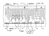
図1は本発明の実施例を示す平面図、図2はその側面図である。
図において、1は放熱板、2(2a,2b,2c,2d,2e,2f)は複数の形状の異なる発熱素子で、各発熱素子2の端子21はそれぞれ基板3に半田付けされている。
4は発熱素子2を放熱板1に固定するための弾性を有する板材からなる固定部材で、複数の発熱素子2を配列した配列方向の長さをもち、かつ断面がL字状の基部41と、基部41の長手方向に対して基部41から直角方向に伸び、かつ、長さの異なる短冊状の板バネ部42とからなっている。基部41には取り付け穴が複数個、長手方向に沿って等間隔に設けられ、ネジ5によって基部41を放熱板1に固定するようにしてある。
板バネ部42は長さが異なる板バネ42a,42b,42cを互いに所定の間隔をあけて設けて一組として複数組設け、各組の板バネは所定のピッチで、連続的に基部41の長手方向に配列してある。
【0006】
発熱素子2を放熱板1に固定する場合、複数の発熱素子2は各端子21を予め基板3に半田付けするとによって基板3に固定しておく。
この状態の発熱素子2を、放熱板1の上に重ね合わせる。次に、固定部材4を発熱素子2の配列方向に沿って配置すると共に、板バネ部42を各発熱素子2の上に重ね合わせ、ネジ5によって放熱板1に固定する。
このとき、板バネ部42は長さが異なる板バネ42a,42b,42cを設けてあるので、一つの発熱素子2に対して板バネ42a,42b,42cのうちの少なくとも2個は、発熱素子2の配列方向および配列方向に直角方向に異なる位置を押えることになる。例えば発熱素子2bでは、一つの固定部材4によって同時にA,B,C,D,E,F,G,Hの8点で押えることになる。
したがって、1個の固定部材4を放熱板1に固定することにより、複数の発熱素子2を同時に放熱板1に固定することができる。
また、各発熱素子2を放熱板1に押し付ける支持点は1か所に集中することがなく、異なる位置の複数箇所で押えるので、放熱板1に対する発熱素子2の浮き上がりを防ぐことができ、各発熱素子2から放熱板1への熱伝達が妨げられることはなくなる。
また、板バネ部42の各板バネ42a,42b,42cは、隣接する板バネとの間に間隔を設けてあるので、相互に他方の板バネのバネ作用の影響を受けることがなく、ぞれぞれ独立した板バネとして機能する。
なお、上記実施例では、板バネ部42の板バネを3種類の長さのものについて説明したが、長さの種類は3個以上でもよく、長さの種類が多いほど多種類の発熱素子を固定することができる。
また、発熱素子の数量が変わっても、固定部材の長さを変えることにより簡単に対応できる。
【0007】
【発明の効果】
以上述べたように、本発明によれば、複数個の発熱素子を同一の放熱板に1個の固定部材で同時に複数個の発熱素子を固定することができるので、固定部材の数および種類を削減でき、かつ作業工数を低減することができる。
また、1個の発熱素子に対して最低2か所を押えることができるので、押し付ける支持点の集中がなく、放熱板に対する発熱素子の浮き上がりを防ぎ、部品点数、および組立て工数の少ない、伝熱効率のよい発熱素子の固定構造を提供できる効果がある。
【図面の簡単な説明】
【図1】 本発明の実施例を示す平断面図である。
【図2】 本発明の実施例を示す側面図である。
【図3】 従来例を示す平断面図である。
【図4】 従来例を示す側面図である。
【図5】 他の従来例を示す平断面図である。
【図6】 他の従来例を示す側面図である。
【符号の説明】
1:放熱板、2、2a,2b,2c,2d,2e,2f:発熱素子、21:端子、3:基板、4:固定部材、41:基部、42:板バネ部、42a,42b,42c:板バネ、5:ネジ 、6:板バネ[0001]
BACKGROUND OF THE INVENTION
The present invention relates to a fixing structure for fixing a plurality of heating elements to the same heat radiating plate.
[0002]
[Prior art]
Conventionally, in order to protect heat generating elements such as power transistors and power ICs from heat, it is attached so as to be in close contact with a heat sink formed using an aluminum plate or the like, and heat generated from the heat generating element is diffused by the heat sink. The heating element is cooled.
In that case, for example, as shown in FIG. 3, the heat generating
[0003]
[Problems to be solved by the invention]
However, in any of the above prior arts, one or more screws, stoppers, and leaf springs are required for each heating element. For this reason, there is a problem that the number of parts and the number of work steps increase as the number of heating elements increases.
In any case, since the pressing support point to the heating element is one point, the state shown in FIG. 4A is changed to the state shown in FIG. 4B, and the state shown in FIG. In the state shown in FIG. 1, there is a problem that the heat generating element is lifted with respect to the heat radiating plate, which hinders heat transfer from the heat generating element to the heat radiating plate.
An object of the present invention is to solve the above problems and to provide a fixing structure of a heat generating element having a small number of parts and a small number of assembly steps and high heat transfer efficiency.
[0004]
[Means for Solving the Problems]
In order to solve the above-described problems, the present invention includes an elastic fixing member and fixing means for fixing the fixing member to a heat sink, and a plurality of heating elements between the fixing member and the heat sink. In the fixing structure of the heating element, the fixing member includes a base portion having a length in an arrangement direction in which the plurality of heating elements are arranged, and a direction perpendicular to the longitudinal direction of the base portion from the base portion. Ri Do and a plurality of leaf spring portions extending, and together with the plate spring portion has a length from the base different to each other and made of strip-shaped plate spring provided at a distance from one another, each of the heating elements On the other hand, it is characterized by being pressed by a plurality of leaf springs having different lengths.
[0005]
DETAILED DESCRIPTION OF THE INVENTION
The present invention will be described below with reference to embodiments shown in the drawings.
FIG. 1 is a plan view showing an embodiment of the present invention, and FIG. 2 is a side view thereof.
In the figure, 1 is a heat dissipation plate, 2 (2a, 2b, 2c, 2d, 2e, 2f) is a plurality of heat generating elements having different shapes, and the
Reference numeral 4 denotes a fixing member made of an elastic plate for fixing the heat generating
The
[0006]
When fixing the heat generating
The
At this time, since the
Therefore, by fixing one fixing member 4 to the
Further, since the supporting points for pressing each
Further, since the
In the above-described embodiment, the leaf springs of the
Further, even if the number of heating elements changes, it can be easily dealt with by changing the length of the fixing member.
[0007]
【The invention's effect】
As described above, according to the present invention, since a plurality of heat generating elements can be simultaneously fixed to the same heat radiating plate with a single fixing member, the number and types of fixing members can be reduced. It can be reduced and the number of work steps can be reduced.
In addition, since at least two places can be pressed against one heating element, there is no concentration of supporting points to be pressed, and the heating element is prevented from lifting up against the heat sink, reducing the number of parts and assembly man-hours. It is possible to provide a heat generating element fixing structure that is excellent in quality.
[Brief description of the drawings]
FIG. 1 is a plan sectional view showing an embodiment of the present invention.
FIG. 2 is a side view showing an embodiment of the present invention.
FIG. 3 is a plan sectional view showing a conventional example.
FIG. 4 is a side view showing a conventional example.
FIG. 5 is a plan sectional view showing another conventional example.
FIG. 6 is a side view showing another conventional example.
[Explanation of symbols]
1: heat sink, 2, 2a, 2b, 2c, 2d, 2e, 2f: heating element, 21: terminal, 3: substrate, 4: fixing member, 41: base, 42: leaf spring, 42a, 42b, 42c : Leaf spring, 5: screw, 6: leaf spring
Claims (1)
前記固定部材は、前記複数の発熱素子を配列した配列方向の長さをもつ基部と、前記基部の長手方向に対して前記基部から直角方向に伸びる複数の板バネ部とからなり、かつ前記板バネ部は前記基部からの長さがそれぞれ異なり、かつ互いに間隔をあけて設けられた短冊状の板バネからなるとともに、それぞれの発熱素子に対して、長さの異なる複数の板バネで押圧したことを特徴とする発熱素子の固定構造。A heating element fixing structure comprising a fixing member having elasticity and a fixing means for fixing the fixing member to a heat sink, wherein a plurality of heat generating elements are fixed between the fixing member and the heat sink. In
The fixing member includes a base portion having a length in the array direction in which an array of a plurality of heating elements, Ri Do and a plurality of leaf spring portion extending perpendicularly from said base portion with respect to the longitudinal direction of said base, and wherein The leaf springs are formed of strip-like leaf springs having different lengths from the base and spaced apart from each other, and are pressed against each heating element by a plurality of leaf springs having different lengths. A heating element fixing structure characterized by that.
Priority Applications (1)
| Application Number | Priority Date | Filing Date | Title |
|---|---|---|---|
| JP11310596A JP3663607B2 (en) | 1996-04-09 | 1996-04-09 | Heating element fixing structure |
Applications Claiming Priority (1)
| Application Number | Priority Date | Filing Date | Title |
|---|---|---|---|
| JP11310596A JP3663607B2 (en) | 1996-04-09 | 1996-04-09 | Heating element fixing structure |
Publications (2)
| Publication Number | Publication Date |
|---|---|
| JPH09283674A JPH09283674A (en) | 1997-10-31 |
| JP3663607B2 true JP3663607B2 (en) | 2005-06-22 |
Family
ID=14603622
Family Applications (1)
| Application Number | Title | Priority Date | Filing Date |
|---|---|---|---|
| JP11310596A Expired - Fee Related JP3663607B2 (en) | 1996-04-09 | 1996-04-09 | Heating element fixing structure |
Country Status (1)
| Country | Link |
|---|---|
| JP (1) | JP3663607B2 (en) |
Families Citing this family (5)
| Publication number | Priority date | Publication date | Assignee | Title |
|---|---|---|---|---|
| US6043981A (en) * | 1997-11-13 | 2000-03-28 | Chrysler Corporation | Heat sink assembly for electrical components |
| WO2010119546A1 (en) * | 2009-04-16 | 2010-10-21 | 三菱電機株式会社 | Fitting for fixing heat producing parts |
| JP2013214770A (en) * | 2013-07-10 | 2013-10-17 | Mitsubishi Electric Corp | Metal fitting and method for fixing heating component |
| JP2016025161A (en) * | 2014-07-17 | 2016-02-08 | 三菱電機株式会社 | Heat radiator |
| JP2021028923A (en) * | 2019-08-09 | 2021-02-25 | Kyb株式会社 | Fixing metal fitting and electronic component unit |
-
1996
- 1996-04-09 JP JP11310596A patent/JP3663607B2/en not_active Expired - Fee Related
Also Published As
| Publication number | Publication date |
|---|---|
| JPH09283674A (en) | 1997-10-31 |
Similar Documents
| Publication | Publication Date | Title |
|---|---|---|
| US5201866A (en) | Structure for dissipation of heat having slidably engaged fins for conformal disposition against a heat generating surface | |
| WO1999019948B1 (en) | Laser diode assembly | |
| JP4202895B2 (en) | Heat sink assembly, heat sink assembly method, and heat sink | |
| JP4643703B2 (en) | Semiconductor device fixture and mounting structure thereof | |
| JP3663607B2 (en) | Heating element fixing structure | |
| US4890196A (en) | Solderable heat sink fastener | |
| CA1209279A (en) | Clip-fastening of a solid state device to a heatsink | |
| JP2000349353A (en) | Peltier module and module for optical communication equipped with the same | |
| JP2002118211A (en) | Radiator of electronic component and manufacturing method of the radiator | |
| US6381137B1 (en) | Semiconductor module | |
| US6453987B1 (en) | Unitary heat-dissipating fin strip unit with straight strip portions and U-shaped strip portions | |
| JPH1117080A (en) | Radiator | |
| JPS6123349A (en) | Radiator | |
| US6369440B1 (en) | Semiconductor substrate and manufacturing method thereof | |
| JPH11312770A (en) | Radiation fin for thin ic | |
| JPH08162680A (en) | Thermo-electric converter | |
| JP3352918B2 (en) | Electronic components | |
| JP2002359330A (en) | Heat sink clamping fitment, heat sink and method for fixing heat sink | |
| JPH05315776A (en) | Cooling structure for parts of surface installation | |
| KR19980033047A (en) | Static Thermistors and Static Thermistor Devices | |
| JPH05315484A (en) | Radiator for semiconductor | |
| JP3050723U (en) | Heat sink with fixings | |
| KR200151238Y1 (en) | Haet sink fixing device | |
| JPH0638429Y2 (en) | Semiconductor element mounting structure | |
| JP3232905B2 (en) | Electrode forming mask |
Legal Events
| Date | Code | Title | Description |
|---|---|---|---|
| A131 | Notification of reasons for refusal |
Free format text: JAPANESE INTERMEDIATE CODE: A131 Effective date: 20041215 |
|
| A521 | Written amendment |
Free format text: JAPANESE INTERMEDIATE CODE: A523 Effective date: 20050214 |
|
| TRDD | Decision of grant or rejection written | ||
| A01 | Written decision to grant a patent or to grant a registration (utility model) |
Free format text: JAPANESE INTERMEDIATE CODE: A01 Effective date: 20050307 |
|
| A61 | First payment of annual fees (during grant procedure) |
Free format text: JAPANESE INTERMEDIATE CODE: A61 Effective date: 20050320 |
|
| R150 | Certificate of patent or registration of utility model |
Free format text: JAPANESE INTERMEDIATE CODE: R150 |
|
| FPAY | Renewal fee payment (event date is renewal date of database) |
Free format text: PAYMENT UNTIL: 20090408 Year of fee payment: 4 |
|
| FPAY | Renewal fee payment (event date is renewal date of database) |
Free format text: PAYMENT UNTIL: 20090408 Year of fee payment: 4 |
|
| FPAY | Renewal fee payment (event date is renewal date of database) |
Free format text: PAYMENT UNTIL: 20100408 Year of fee payment: 5 |
|
| FPAY | Renewal fee payment (event date is renewal date of database) |
Free format text: PAYMENT UNTIL: 20100408 Year of fee payment: 5 |
|
| FPAY | Renewal fee payment (event date is renewal date of database) |
Free format text: PAYMENT UNTIL: 20110408 Year of fee payment: 6 |
|
| FPAY | Renewal fee payment (event date is renewal date of database) |
Free format text: PAYMENT UNTIL: 20120408 Year of fee payment: 7 |
|
| FPAY | Renewal fee payment (event date is renewal date of database) |
Free format text: PAYMENT UNTIL: 20120408 Year of fee payment: 7 |
|
| FPAY | Renewal fee payment (event date is renewal date of database) |
Free format text: PAYMENT UNTIL: 20130408 Year of fee payment: 8 |
|
| LAPS | Cancellation because of no payment of annual fees |