JP3663430B2 - Drilling blade mounting structure - Google Patents
Drilling blade mounting structure Download PDFInfo
- Publication number
- JP3663430B2 JP3663430B2 JP25157696A JP25157696A JP3663430B2 JP 3663430 B2 JP3663430 B2 JP 3663430B2 JP 25157696 A JP25157696 A JP 25157696A JP 25157696 A JP25157696 A JP 25157696A JP 3663430 B2 JP3663430 B2 JP 3663430B2
- Authority
- JP
- Japan
- Prior art keywords
- blade
- drilling
- opening
- side wall
- screw
- Prior art date
- Legal status (The legal status is an assumption and is not a legal conclusion. Google has not performed a legal analysis and makes no representation as to the accuracy of the status listed.)
- Expired - Fee Related
Links
Images


Landscapes
- Drilling Tools (AREA)
Description
【0001】
【発明の属する技術分野】
本発明は穿孔具に装着する穿孔刃の取付け構造に関するものであり、より詳しくは、穿孔刃の着脱作業が簡単、かつ安全に実施できる穿孔刃の取付け構造の提供に関するものである。
【0002】
【従来の技術】
従来、被穿孔体に対して透孔を穿孔する目的で使用される穿孔具に装着する穿孔刃の取付け方法としては、図7にその要部を分解斜視図で示すように、螺刻された雌ネジ31を有する穿孔刃取付け座32がアーム33の両端部に設けられ、該穿孔刃取付け座32に、前記雌ネジ31と穿孔刃34に形成された貫通孔35が重なるように穿孔刃34を配置し、該貫通孔35を挿通して備えられたビス36等を介して締め付け固定するようになっている。
【0003】
【発明が解決しようとする課題】
しかしながら、従来の穿孔刃の取付け方法にあっては、穿孔刃取付け座32に対して穿孔刃33を固定できるものの、被穿孔体に対して透孔を穿設している最中に穿孔刃33がビス36等を軸心として回転若しくは回動することがあり、これが原因となって仕上がりの美しい透孔を穿設できないことがあった。
【0004】
また、前記穿孔刃取付け座32に雌ネジ31と穿孔刃34に形成された貫通孔35とが重なるように穿孔刃34を配置させ、ついで、貫通孔35を挿通して備えられたビス36等で締め付け固定する作業がまことに面倒である上に、貫通孔35から穿孔刃34の先端までの長さを自在に調節することができなかったから、多種類の穿孔刃を予め準備しておき、厚さの異なる被穿孔体毎にその都度穿孔刃を選別し交換する作業をしなければならなかった。
【0005】
特に、切りかす受けカバー体を有する穿孔具において、カバー体内の狭いところで穿孔刃の取付け、取り外し作業をしなければならないので、穿孔刃の交換に不便で交換に時間がかかる上、手指をけがすることも多く、その改良が望まれていた。
【0006】
そこで、本発明は、穿孔刃の着脱作業が簡単かつ安全に実施できる穿孔刃の取付け構造を創案し提供することをその解決すべき課題とするものである。
【0007】
【課題を解決するための手段】
上記課題を課題を解決するために採った請求項1の発明の要旨とするところは、被穿孔体に対して透孔を穿孔する目的で使用される穿孔具に穿孔刃を装着するようにした穿孔刃の取付け構造であって、
前記穿孔具は、穿孔刃を保持させる回動体もしくは固定体と、穿孔刃による切りかすの飛散を防止するカバー体とを備え、
前記カバー体は、下方の開口を分断することなく側方に開口する開口部が側壁面の一部に形成されると共に前記回動体もしくは固定体の全体を覆うカップ状の脚と、前記開口部に着脱自在に設けられて該開口部を覆うための蓋部材とを備え、
前記回動体もしくは固定体は、一側壁の外面に雌ネジが螺刻され、該雌ネジに螺着されるビスのビス頭と前記側壁との間で前記穿孔刃を挟持し、
前記開口部は前記蓋部材を取外すことにより開口し、前記ビスは該開口部を介して前記カバー体の外側から操作が可能であることを特徴とするものであり、前記カバー体の開口部を開口しても穿孔刃はカバー体で覆われているために、作業者は、カバー体の開口部を介してカバー体の外側からビスを操作しても、作業者が不用意に、穿孔刃に接触することがなく、作業者は指等に傷を負わない。
【0008】
請求項2の発明の要旨とするところは、請求項1に記載の穿孔刃取付け構造であって、回転体若しくは固定体の側壁外面に、穿孔刃を収容し得る上下方向の凹溝が形成されていることを特徴とするものであり、請求項1に記載の作用に加えて、特には、回動体5若しくは固定体3の側壁外面に形成された上下方向の凹溝3bに穿孔刃4の一部を収容でき、該穿孔刃4自体の回転若しくは回動を防止できる。すなわち、仕上がりの美しい透孔を被穿孔体に対して穿設できる。
【0011】
【発明の実施の形態】
本発明を、穿孔刃の取付け構造を具体化した実施例に基づいて説明する。
図1は、本発明の実施例の穿孔刃4の取付け構造を具有した穿孔具20の一部破断正面図、図2は同じく一部破断側面図であり、図3(a)は回転軸1と一体となって回転する回転体5の正面図、図3(b)は同じく底面図であり、図4(a)は本実施例の穿孔刃の固定体の平面図であり、図4(b)は同じく正面図である。
【0012】
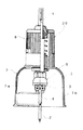
図において、本発明の実施例の穿孔具20は、被穿孔体に対して透孔を穿設する際に使用するものであり、
ハンディータイプの回転駆動工具に先端が着脱自在に取付され、該回転駆動工具により回転駆動する回転軸1と、該回転軸1に一端が着脱自在に止着され被穿孔体に穿設する透孔10の穿孔中心の位置を提供するセンター軸2と、前記透孔10の穿孔中心の位置と同心状の中心貫通孔5aが形成され該中心貫通孔5aに前記回転軸1の下方が着脱自在に挿嵌され、かつ前記中心貫通孔5aより所定の間隔離間した相対向する両側に、固定体3を介して穿孔刃4を取り付けた回転体5とからなる本体ブロック6と、
側壁面に開口部7aが設けられ前記回転体5の全体を覆うカップ状の脚7bと、該脚7bの上部に一体形成され前記回転軸1が挿通される挿通孔を設けた筒状部7cと、前記開口部7aに着脱自在に係止させ該開口部7aの全体を覆うための蓋部材7dとからなるカバー体7と、
該カバー体7の上面に固設され前記本体ブロック6の移動距離を制限する切込み深さ調節装置8と、を含み構成されている。
【0013】
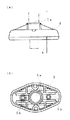
前記回転体5には、被穿孔体に穿設する透孔10の中心位置と同心状の中心貫通孔5aが形成されており、該中心貫通孔5aの内面には軸線方向へ切欠いた凹部が形成され、この凹部に前記回転軸1の下方外面に形成された凸部が枢支させた状態で挿脱自在に挿入可能で回り止めが施された状態で止着できるようになっている。
【0014】
また、この回転体5には、図5に示すように、前記センター軸2をとおる放射線上であってかつセンター軸2の軸心を対称中心とする位置にそれぞれナット形状に形成された雌ネジ5bが形成されており、この雌ネジ5bに、突出方向に向けて配置された穿孔刃4の固定体3をビス5cを介してビス止めできるようになっている。
【0015】
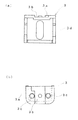
前記穿孔刃4の取付け構造は、図6に示すように、略筺体形状に一体形成された固定体3の外側の側壁外面に上端に切欠部3aを有する上下方向の凹溝3bが形成され、この凹溝3bに穿孔刃4の上方が保持される。また、凹溝3bの両側に雌ネジ3cが螺刻されており、該雌ネジ3cに螺着せしめたビス3eのビス頭と固定体3の側壁との間に、穿孔刃4を挟持させるようになっている。
【0016】
また、図4(a)に示すように、この固定体3の底面中央部には、穿孔刃4を備えた側壁と直交する方向に向けて長孔3dが形成されており、該長孔3dを貫通して備えられたビス5cを緩めることにより、固定体3自体を前記センター軸2の半径方向の所望する位置にスライド移動させることができ、そのままビス5cで締め付け固定できるようになっている。
すなわち、センター軸2と固定体3との間の距離は無段階に設定できるから、穿孔径の異なる様々な穿孔10を被穿孔体に対して穿設できるように機能する。
【0017】
穿孔刃4は、その刃先がV字形状であり刃厚方向で外側から内側に向けて傾斜させた形状に形成されており、また、上端には幅方向に膨出させた係合部4aが形成されており、この係合部4aを前記固定体3の切欠部3aに係合させない限り取付け不可になっている。すなわち、穿孔刃は、位置決めされた状態でしか取付けできない。
【0018】
なお、回転体5にコイルスプリング(弾性体)を介在させ該スプリングの弾発力に抗して穿孔刃4の固定体3を密接固定できる構成であると、この固定体3は回転体5に対して離間する方向に向けて常時付勢されているから、ビスを緩めて固定解除することにより固定体3自体を簡単に取り外すことができる。すなわち、特には、切りかすカバー体7を有する穿孔具である場合には、カバー体7内の狭いところで穿孔刃4の交換作業を行わなくてもよいから、手指をけがすることなく穿孔刃4の取付け、取り外し、及び交換作業を安全に行える。
【0019】
また、穿孔刃を取り替えする時にあっては、前記カバー体7に備えられた蓋体7bを取り外すことにより簡単に開口部7aを開口させることができ、例えば従来のかかる穿孔具のごとき、カバー体の下方の開口からL字六角レンチ等を挿入してビスの操作を行なうのとは異なり、上記と同様、開口部7aの外側から、この開口部7aを介して、ドライバーのみで前記ビス3e止め等の操作できるから、穿孔刃の交換作業が迅速且つ安全に行えるとともに、カバー体全体の大きさを縮小できる。
【0020】
ところで、本発明の穿孔刃取付け構造は、固定体3の外側の側壁外面に上下方向の凹溝3bが形成され、この凹溝3bに穿孔刃4の上方を保持するとともに、凹溝3bの両側に螺刻された雌ネジ3cに螺着せしめたビス3eのビス頭と前記固定体3の側壁との間に、穿孔刃4を挟持させるようになっており、かつ、固定体に保持せしめた穿孔刃のそれぞれを、センター軸を中心として同一の円軌跡を描くように固定されているところに構成特徴がある。
【0021】
したがって、前記実施例に限定されることなく、例えば前記回転体5の側壁外面上に、上述した穿孔刃4の取付け構造を形成する等、この発明の趣旨から逸脱しない範囲で適宜設計変更して実施できることは、繰り返して述べるまでもないことである。
【0022】
【発明の効果】
以上述べたように、本発明の穿孔刃取付け構造によれば、カバー体の下方の開口を分断することなく側方に開口する開口部が側壁面の一部に形成されていることにより、開口部を開口しても穿孔刃はカバー対で覆われているため安全である。
【0023】
請求項2に記載の発明の穿孔刃取付け構造によれば、回動体若しくは固定体の側壁外面に形成された上下方向の凹溝に、穿孔刃の一部を収容した状態で固定できるから、穿孔刃自体の回動若しくは回動を確実に防止できる。すなわち、回動体若しくは固定体に保持せしめた穿孔刃のそれぞれを、センター軸を中心として同一の円軌跡を描くように固定できるから、仕上がりの美しい透孔を被穿孔体に対して迅速かつ正確に穿設できる。
【図面の簡単な説明】
【図1】図1は、本発明の実施例の穿孔刃の取付け構造を具備した穿孔具の一部破断正面図である。
【図2】図2は、図1の穿孔具の一部破断側面図である。
【図3】図3(a)は回転軸と一体となって回転する回転体の正面図であり、図3(b)は同じく底面図である。
【図4】図4(a)は本実施例の穿孔刃の固定体の平面図であり、図4(b)は同じく正面図である。
【図5】図5は、回転体に固定体を取付けする方法を説明するための要部分解正面図である。
【図6】図6は、固定体に穿孔刃を取付けする方法を説明するための要部分解斜視図である。
【図7】図7は、従来の穿孔刃の取付け方法を説明するための要部分解斜視図である。
【符号の説明】
1…回転軸
2…センター軸
3…固定体
3a…切欠部
3b…凹溝
3c…雌ネジ
3d…長孔
3e…ビス
4…穿孔刃
4a…係合部
5…回転体
5a…中心貫通孔
5b…雌ネジ
5c…ビス
6…本体ブロック
7…カバー体
7a…開口部
7b…カップ状の脚
7c…筒状部
7d…蓋部材
8…切込み深さ調節装置
10…透孔
20…穿孔具
31…雌ネジ
32…穿孔刃取付け座
33…アーム
34…穿孔刃
35…貫通孔
36…ビス[0001]
BACKGROUND OF THE INVENTION
The present invention relates to a mounting structure for a drilling blade to be mounted on a drilling tool, and more particularly to the provision of a mounting structure for a drilling blade that can be attached and detached easily and safely.
[0002]
[Prior art]
Conventionally, as a method of attaching a drilling blade to be mounted on a drilling tool used for the purpose of drilling a through-hole in a drilled body, the main part thereof is screwed as shown in an exploded perspective view in FIG. A perforation blade mounting seat 32 having a
[0003]
[Problems to be solved by the invention]
However, in the conventional method for attaching a perforating blade, although the perforating
[0004]
Further, the
[0005]
In particular, in a drilling tool having a scissor receiving cover body, it is necessary to install and remove the drilling blade in a narrow space within the cover body. There were many things, and the improvement was desired.
[0006]
Accordingly, an object of the present invention is to devise and provide a drilling blade mounting structure that allows the drilling blade to be attached and detached easily and safely.
[0007]
[Means for Solving the Problems]
The gist of the invention of
The piercing tool includes a rotating body or a fixed body that holds the piercing blade, and a cover body that prevents scattering of chips by the piercing blade,
The cover body has a cup-like leg that covers the entire rotating body or fixed body, and an opening that opens to the side without dividing the lower opening is formed on a part of the side wall surface, and the opening. A lid member that is detachably provided to cover the opening,
The rotating body or the fixed body has a female screw threaded on the outer surface of one side wall, and sandwiches the drilling blade between the screw head screwed to the female screw and the side wall,
The opening portion is opened by removing the lid member, and the screw can be operated from the outside of the cover body through the opening portion, and the opening portion of the cover body is formed. Since the drilling blade is covered with the cover body even if it is opened, even if the operator operates the screw from the outside of the cover body through the opening of the cover body, the operator carelessly operates the drilling blade. The operator does not touch the finger or the like.
[0008]
The gist of the invention of
[0011]
DETAILED DESCRIPTION OF THE INVENTION
The present invention will be described based on an embodiment in which a drilling blade mounting structure is embodied.
1 is a partially broken front view of a
[0012]
In the figure, a
A
A cylindrical portion 7c provided with a cup-like leg 7b provided with an opening 7a on the side wall surface and covering the entire
A cut depth adjusting
[0013]
The rotating
[0014]
Further, as shown in FIG. 5, the
[0015]
As shown in FIG. 6, the mounting structure of the
[0016]
As shown in FIG. 4 (a), a long hole 3d is formed in the center of the bottom surface of the
That is, since the distance between the
[0017]
The
[0018]
If the
[0019]
Further, when replacing the drilling blade, the opening 7a can be easily opened by removing the lid 7b provided on the
[0020]
By the way, in the perforated blade mounting structure of the present invention, a vertical concave groove 3b is formed on the outer surface of the outer side wall of the fixed
[0021]
Accordingly, the present invention is not limited to the above-described embodiment. For example, the above-described
[0022]
【The invention's effect】
As described above, according to the perforated blade mounting structure of the present invention, the opening portion that opens to the side without dividing the opening below the cover body is formed in a part of the side wall surface. Even if the part is opened, the drilling blade is covered with the cover pair, which is safe.
[0023]
According to the drilling blade mounting structure of the second aspect of the present invention, the drilling blade can be fixed in a state where a part of the drilling blade is accommodated in the vertical groove formed on the outer side wall of the rotating body or the fixed body. The rotation or rotation of the blade itself can be reliably prevented. That is, since each of the drilling blades held by the rotating body or the fixed body can be fixed so as to draw the same circular locus around the center axis, a beautifully finished through hole can be quickly and accurately applied to the drilled body. Can be drilled.
[Brief description of the drawings]
FIG. 1 is a partially cutaway front view of a drilling tool having a drilling blade mounting structure according to an embodiment of the present invention.
FIG. 2 is a partially cutaway side view of the punching device of FIG. 1;
FIG. 3A is a front view of a rotating body that rotates integrally with a rotating shaft, and FIG. 3B is a bottom view of the same.
FIG. 4 (a) is a plan view of a fixed body of a drilling blade according to the present embodiment, and FIG. 4 (b) is a front view of the same.
FIG. 5 is an exploded front view of a main part for explaining a method of attaching a fixed body to a rotating body.
FIG. 6 is an exploded perspective view of a main part for explaining a method of attaching a drilling blade to a fixed body.
FIG. 7 is an exploded perspective view of a main part for explaining a conventional method for attaching a drilling blade.
[Explanation of symbols]
DESCRIPTION OF
Claims (2)
前記穿孔具は、穿孔刃を保持させる回動体もしくは固定体と、穿孔刃による切りかすの飛散を防止するカバー体とを備え、
前記カバー体は、下方の開口を分断することなく側方に開口する開口部が側壁面の一部に形成されると共に前記回動体もしくは固定体の全体を覆うカップ状の脚と、前記開口部に着脱自在に設けられて該開口部を覆うための蓋部材とを備え、
前記回動体もしくは固定体は、一側壁の外面に雌ネジが螺刻され、該雌ネジに螺着されるビスのビス頭と前記側壁との間で前記穿孔刃を挟持し、
前記開口部は前記蓋部材を取外すことにより開口し、前記ビスは該開口部を介して前記カバー体の外側から操作が可能であることを特徴とする穿孔刃取付け構造。A mounting structure of a punching blade which is adapted to mount the cutting head on the drilling tool is used for the purpose of drilling a hole with respect to the drilling member,
The piercing tool includes a rotating body or a fixed body that holds the piercing blade, and a cover body that prevents scattering of chips by the piercing blade,
The cover body has a cup-like leg that covers the entire rotating body or fixed body, and an opening that opens to the side without dividing the lower opening is formed on a part of the side wall surface, and the opening. A lid member that is detachably provided to cover the opening,
The rotating body or the fixed body has a female screw threaded on the outer surface of one side wall, and sandwiches the drilling blade between the screw head screwed to the female screw and the side wall,
The opening portion is opened by removing the lid member, and the screw can be operated from the outside of the cover body through the opening portion .
Priority Applications (1)
| Application Number | Priority Date | Filing Date | Title |
|---|---|---|---|
| JP25157696A JP3663430B2 (en) | 1996-09-24 | 1996-09-24 | Drilling blade mounting structure |
Applications Claiming Priority (1)
| Application Number | Priority Date | Filing Date | Title |
|---|---|---|---|
| JP25157696A JP3663430B2 (en) | 1996-09-24 | 1996-09-24 | Drilling blade mounting structure |
Publications (2)
| Publication Number | Publication Date |
|---|---|
| JPH1094909A JPH1094909A (en) | 1998-04-14 |
| JP3663430B2 true JP3663430B2 (en) | 2005-06-22 |
Family
ID=17224877
Family Applications (1)
| Application Number | Title | Priority Date | Filing Date |
|---|---|---|---|
| JP25157696A Expired - Fee Related JP3663430B2 (en) | 1996-09-24 | 1996-09-24 | Drilling blade mounting structure |
Country Status (1)
| Country | Link |
|---|---|
| JP (1) | JP3663430B2 (en) |
Families Citing this family (1)
| Publication number | Priority date | Publication date | Assignee | Title |
|---|---|---|---|---|
| JP5285504B2 (en) * | 2009-05-21 | 2013-09-11 | 未来工業株式会社 | Drilling tool |
-
1996
- 1996-09-24 JP JP25157696A patent/JP3663430B2/en not_active Expired - Fee Related
Also Published As
| Publication number | Publication date |
|---|---|
| JPH1094909A (en) | 1998-04-14 |
Similar Documents
| Publication | Publication Date | Title |
|---|---|---|
| KR930007576B1 (en) | Paper cutter and cutting method | |
| US5049012A (en) | Auxiliary handle for hand-held drill | |
| US6120220A (en) | Rotary cutting tool | |
| US7044042B2 (en) | Blade cutting assembly for sheet material | |
| JPH11277315A (en) | Chamfering machine | |
| JP3663430B2 (en) | Drilling blade mounting structure | |
| US4984613A (en) | Hinge mortise guide and cutter | |
| JP3163392B2 (en) | Perforator with chipping cover | |
| JP3663431B2 (en) | Drilling blade mounting device for drilling tool | |
| JP2000052259A (en) | Fence for vise device | |
| JP3965503B2 (en) | Drilling tool with chip receiving cover | |
| KR100974375B1 (en) | Rotary cutter device | |
| JP3676700B2 (en) | Tank drilling equipment | |
| US5829929A (en) | Long bit hole saw arbor | |
| JPH1094997A (en) | Rotation preventing structure for punching blade | |
| JP2601114B2 (en) | Dropping device for drilling debris in electric drilling machine | |
| KR200243387Y1 (en) | Hole cutter | |
| JP2005153079A (en) | Device for mounting rotary grinding tool | |
| JP4463647B2 (en) | Drilling tool | |
| JP2005144649A (en) | Wall hole boring tool | |
| JP3084133B2 (en) | Rotary cutting tool | |
| JP3572574B2 (en) | Perforator and gauge | |
| JPH09225894A (en) | Protecting cover of cutter knife | |
| JP4275220B2 (en) | Milling equipment | |
| JPH0621683Y2 (en) | Circular saw with cutting edge for drilling |
Legal Events
| Date | Code | Title | Description |
|---|---|---|---|
| A977 | Report on retrieval |
Free format text: JAPANESE INTERMEDIATE CODE: A971007 Effective date: 20041105 |
|
| A131 | Notification of reasons for refusal |
Free format text: JAPANESE INTERMEDIATE CODE: A131 Effective date: 20041122 |
|
| A521 | Written amendment |
Free format text: JAPANESE INTERMEDIATE CODE: A523 Effective date: 20050120 |
|
| TRDD | Decision of grant or rejection written | ||
| A01 | Written decision to grant a patent or to grant a registration (utility model) |
Free format text: JAPANESE INTERMEDIATE CODE: A01 Effective date: 20050228 |
|
| A61 | First payment of annual fees (during grant procedure) |
Free format text: JAPANESE INTERMEDIATE CODE: A61 Effective date: 20050303 |
|
| R150 | Certificate of patent or registration of utility model |
Free format text: JAPANESE INTERMEDIATE CODE: R150 |
|
| FPAY | Renewal fee payment (event date is renewal date of database) |
Free format text: PAYMENT UNTIL: 20080408 Year of fee payment: 3 |
|
| FPAY | Renewal fee payment (event date is renewal date of database) |
Free format text: PAYMENT UNTIL: 20090408 Year of fee payment: 4 |
|
| FPAY | Renewal fee payment (event date is renewal date of database) |
Free format text: PAYMENT UNTIL: 20090408 Year of fee payment: 4 |
|
| FPAY | Renewal fee payment (event date is renewal date of database) |
Free format text: PAYMENT UNTIL: 20090408 Year of fee payment: 4 |
|
| FPAY | Renewal fee payment (event date is renewal date of database) |
Free format text: PAYMENT UNTIL: 20100408 Year of fee payment: 5 |
|
| FPAY | Renewal fee payment (event date is renewal date of database) |
Free format text: PAYMENT UNTIL: 20100408 Year of fee payment: 5 |
|
| FPAY | Renewal fee payment (event date is renewal date of database) |
Free format text: PAYMENT UNTIL: 20110408 Year of fee payment: 6 |
|
| FPAY | Renewal fee payment (event date is renewal date of database) |
Free format text: PAYMENT UNTIL: 20110408 Year of fee payment: 6 |
|
| FPAY | Renewal fee payment (event date is renewal date of database) |
Free format text: PAYMENT UNTIL: 20120408 Year of fee payment: 7 |
|
| FPAY | Renewal fee payment (event date is renewal date of database) |
Free format text: PAYMENT UNTIL: 20120408 Year of fee payment: 7 |
|
| FPAY | Renewal fee payment (event date is renewal date of database) |
Free format text: PAYMENT UNTIL: 20130408 Year of fee payment: 8 |
|
| FPAY | Renewal fee payment (event date is renewal date of database) |
Free format text: PAYMENT UNTIL: 20130408 Year of fee payment: 8 |
|
| FPAY | Renewal fee payment (event date is renewal date of database) |
Free format text: PAYMENT UNTIL: 20140408 Year of fee payment: 9 |
|
| R250 | Receipt of annual fees |
Free format text: JAPANESE INTERMEDIATE CODE: R250 |
|
| LAPS | Cancellation because of no payment of annual fees |