JP3662011B2 - Remote control reception system - Google Patents
Remote control reception system Download PDFInfo
- Publication number
- JP3662011B2 JP3662011B2 JP2003291598A JP2003291598A JP3662011B2 JP 3662011 B2 JP3662011 B2 JP 3662011B2 JP 2003291598 A JP2003291598 A JP 2003291598A JP 2003291598 A JP2003291598 A JP 2003291598A JP 3662011 B2 JP3662011 B2 JP 3662011B2
- Authority
- JP
- Japan
- Prior art keywords
- remote control
- data
- circuit
- cpu
- header
- Prior art date
- Legal status (The legal status is an assumption and is not a legal conclusion. Google has not performed a legal analysis and makes no representation as to the accuracy of the status listed.)
- Expired - Fee Related
Links
Images


Classifications
-
- G—PHYSICS
- G08—SIGNALLING
- G08C—TRANSMISSION SYSTEMS FOR MEASURED VALUES, CONTROL OR SIMILAR SIGNALS
- G08C17/00—Arrangements for transmitting signals characterised by the use of a wireless electrical link
Landscapes
- Engineering & Computer Science (AREA)
- Computer Networks & Wireless Communication (AREA)
- Physics & Mathematics (AREA)
- General Physics & Mathematics (AREA)
- Selective Calling Equipment (AREA)
Description
本発明は、リモコンによる制御をうける機器に設けられるリモコン受信システムに関し、特に、該リモコン受信システムにおけるCPUが受ける処理上の負担やリソースの負担を軽減するリモコン受信システムに関する。 The present invention relates to a remote control reception system provided in a device to be controlled by a remote control, and more particularly to a remote control reception system that reduces processing burdens and resource burdens received by a CPU in the remote control reception system.
リモコンによる制御を受ける機器において、送信機から発信されたリモコン信号を受信する受信側に必要な機能は、該リモコン信号を正確にデータに復調する受信機能と、復調して得られたデータをデコードして要求内容を得るデコード機能である。
ここでまず、図21及び図22を用いて、リモコンから発信されるリモコン信号について説明する。図21は、リモコンから発信されるリモコン信号の一例を示す図である。
In equipment that is controlled by a remote controller, the functions required on the receiving side to receive the remote control signal transmitted from the transmitter are the reception function that accurately demodulates the remote control signal into data, and the data that is demodulated is decoded. This is a decoding function for obtaining the requested content.
First, a remote control signal transmitted from the remote controller will be described with reference to FIGS. 21 and 22. FIG. 21 is a diagram illustrating an example of a remote control signal transmitted from the remote controller.
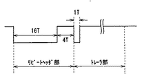
図21(a)に示すように、ここで用いられるリモコン信号は、リモコン信号が以後に続くことを示すヘッダ部と、押下されたリモコンボタンを示すデータのビット列をリモコン信号のLowの持続時間(以下、「LongLow」と称す。)とHighの持続時間(以下、「LongHigh」と称す。)の組み合わせによって表現したデータ部と、前記データの終了を知らせるトレーラ部とからなっている。 As shown in FIG. 21A, the remote control signal used here includes a header portion indicating that the remote control signal continues and a bit string of data indicating the pressed remote control button, and a low duration ( Hereinafter, it is composed of a data portion expressed by a combination of “Long Low” and a high duration (hereinafter referred to as “Long High”), and a trailer portion for informing the end of the data.
なお、図21(a)においては、前記データ部のLongLowとLongHighのデューティが1:1ならばデータ“0”に、1:3ならばデータ“1”に対応しており、そのデータ部のデータのパターンは、少なくとも押下するリモコンボタンの数は存在するものとする。 In FIG. 21 (a), if the Long Low and Long High duty of the data part is 1: 1, it corresponds to data “0”, and if 1: 3, the data part corresponds to data “1”. It is assumed that the data pattern has at least the number of remote control buttons to be pressed.
そして、前述したようなリモコン信号を発信する送信機には、図22(a),(b)に示されるリモコン信号を出力する2種類あり、1つ目は、図22(a)に示されるように、同じリモコンボタンが連続的に押下された場合に、最初の1回だけ図21(a)に示すようなデータ部を伴う波形を発信し、その後は該リモコンボタンが押下されつづける限り、図21(b)に示すようなデータ部を伴わない、リピートヘッダ部及びトレーラ部からなる波形を発信するリピートヘッダ型の送信機であり、2つ目は、図22(b)に示されるように、前記図21(a)に示すデータ部を伴う波形を該リモコンボタンが押下されている間繰り返し発信しつづける繰り返しデータ型の送信機が存在する。 There are two types of transmitters that transmit remote control signals as described above, and output the remote control signals shown in FIGS. 22A and 22B. The first is shown in FIG. As described above, when the same remote control button is continuously pressed, a waveform with a data portion as shown in FIG. 21 (a) is transmitted only once, as long as the remote control button is continuously pressed. A repeat header type transmitter that transmits a waveform composed of a repeat header portion and a trailer portion without a data portion as shown in FIG. 21 (b), and the second is as shown in FIG. 22 (b). In addition, there is a repetitive data type transmitter that repeatedly transmits a waveform with a data portion shown in FIG. 21A while the remote control button is pressed.
次に、前述したリモコン信号を受信する受信側に必要な、デコード機能と受信機能について述べる。
前記デコード機能においては、復調したデータとその要求内容との柔軟な対応づけが必要となるため、該デコード機能をCPUによって実現させることが望ましい。これに対し、前記受信側の前記受信機能については、従来より、以下に示す2つの方法のうちのどちらかで実現されている。
Next, a decoding function and a receiving function necessary for the receiving side that receives the above-described remote control signal will be described.
In the decoding function, since it is necessary to flexibly associate the demodulated data with the requested contents, it is desirable to realize the decoding function by the CPU. On the other hand, the receiving function on the receiving side is conventionally realized by one of the following two methods.
1つ目の方法は、送信機から発信されたリモコン信号を、受信側のCPUに直接入力し、該リモコン信号のエッジを割り込みトリガとし、その割り込み間隔をCPUに内蔵されたタイマ(図示せず)でカウントすることで、CPUによって前記受信機能を実現させる方法である。 In the first method, a remote control signal transmitted from a transmitter is directly input to a CPU on the reception side, an edge of the remote control signal is used as an interrupt trigger, and the interrupt interval is set to a timer (not shown) built in the CPU. ) To realize the reception function by the CPU.
しかし、この1つ目の方法を用いた場合、該リモコン信号の判別のために行う、ヘッダ部の検出、データの0/1判定、トレーラ部の検出等のすべての処理を、前記CPUが引き受けることとなり、この結果、CPUは非常に複雑なソフトウェア処理を行わなければならず、CPUのプログラムステップ数が増大するという問題が生じる。
However, when this first method is used, the CPU takes care of all processing such as header portion detection,
また、この1つ目の方法では、発生するリモコン信号のエッジを直接CPUへの割り込み信号として扱うため、リモコンボタン押下時にはリモコン信号に由来する割り込みが非常に高い頻度で発生する。そして、このリモコン信号に由来する割り込みは、前記リモコン信号を判別するために、該CPUに発生した割り込みの間隔を正確にタイマでカウントしなければならないので、リアルタイム性の要請が厳しく、他の割り込みに比べて高い優先度を与えなければならない。従って、前記1つ目の方法を用いれば、前記CPUに対して、高い優先度の割り込みが高い頻度で発生することとなり、CPUが本来制御しようとするシステムの処理を圧迫して、動作の遅延を招く恐れもあるという問題も生じる。 Further, in this first method, since the edge of the generated remote control signal is directly handled as an interrupt signal to the CPU, an interrupt derived from the remote control signal is generated at a very high frequency when the remote control button is pressed. The interrupt derived from the remote control signal must accurately count the interrupt interval generated in the CPU with a timer in order to discriminate the remote control signal. Must be given higher priority than Therefore, if the first method is used, a high-priority interrupt is generated at a high frequency for the CPU, and the processing of the system that the CPU originally intends to control is compressed, thereby delaying the operation. There is also a problem that there is a risk of incurring.
そこで、従来においては、リモコン信号の受信機能を実現する2つ目の方法として、前記リモコン信号に由来する割り込みの発生数を軽減し、且つCPUの処理負担を軽減するために、該リモコン信号を受信する受信側に、前記リモコン信号の入力を受け、ヘッダ部の検出やデータ部の検出などの復調処理の一部もしくは全部を行うリモコン受信回路を設ける方法がとられている(特許文献1〜3参照)。 Therefore, in the prior art, as a second method for realizing the remote control signal reception function, in order to reduce the number of interrupts originating from the remote control signal and reduce the processing load on the CPU, the remote control signal is used. A method of providing a remote control receiving circuit for receiving a remote control signal input and performing a part or all of demodulation processing such as detection of a header part and detection of a data part is adopted on the receiving side. 3).
以下、図23及び図24を用いて、リモコン信号の受信機能を、2つ目の方法、つまりリモコン受信回路を用いて実現するリモコン受信システムについて説明する。なお、リモコン受信回路に入力されるリモコン信号は、図21に示されているものとする。
まず、図23を用いて、受信側に設ける従来のリモコン受信システムの構成について説明する。図23は、従来におけるリモコン受信システムの構成を示す図である。
Hereinafter, a remote control reception system that realizes a remote control signal reception function using the second method, that is, a remote control reception circuit, will be described with reference to FIGS. It is assumed that the remote control signal input to the remote control receiving circuit is shown in FIG.
First, the configuration of a conventional remote control receiving system provided on the receiving side will be described with reference to FIG. FIG. 23 is a diagram showing a configuration of a conventional remote control reception system.
図23において、従来のリモコン受信システムは、送信機(図示せず)から発信されるリモコン信号を受信するリモコン受信回路500と、該リモコン受信回路500を制御し、前記リモコン信号をデコードするCPU590とからなるものであり、前記リモコン受信回路500は、受信したリモコン信号のエッジを検出するエッジ検出回路510と、該エッジ検出回路510にて検出されたエッジの間隔をカウントするカウンタ回路520と、該カウンタ回路520の出力を受信して、前記リモコン信号のヘッダ部を検出するヘッダ検出回路530と、前記リモコン信号のヘッダ部が検出されたことをCPU590に知らせるヘッダ割り込み信号S560を生成するヘッダ割り込み生成回路560と、前記リモコン信号のヘッダ部に続くデータ部の0/1を前記カウンタ回路520の出力より判別して内蔵レジスタ550にストアするデータ判別回路540と、前記内蔵レジスタ550にリモコン信号のデータ部に相当するビット数分のデータがストアされた時に、リモコン信号のデータ部が検出されたことをCPU590に知らせるデータ割り込み信号S570を生成するデータ割り込み生成回路570と、前記カウンタ回路520の出力を受信して、前記リモコン信号のトレーラ部を検出し、リモコン信号のトレーラ部が検出されたことをCPU590に知らせるトレーラ割り込み信号S580を出力するトレーラ検出回路580と、からなるものである。なお、リモコン受信回路500は、前述したすべての回路を備えている必要はなく、前記エッジ検出回路510、前記カウンタ回路520、前記データ判別回路540を含む、前述したリモコン受信回路の一部からなるものであればよく、例えば前記エッジ検出回路510、前記カウンタ回路520、前記データ判別回路540、及び前記データ割り込み生成回路570で構成されるものであってもよい。
23, a conventional remote control receiving system includes a remote
そして、前記CPU590は、前述したリモコン受信回路500から出力される割り込み信号S560〜S580を受けとり、該受け取った割り込み信号に応じた制御を行うものであり、1つの割り込み信号に対して1つの割り込みポートを利用するため、図23では、CPU590には、3つの割り込みポート0,1,2が設けられている。
The
次に、図24を用いて、前述した構成を有する従来のリモコン受信システムにおいて、リモコン信号を受信した場合の処理の流れについて説明する。図24は、従来におけるリモコン受信システムにおいてリモコン信号を受信した際の動作の一連の流れを示すフローチャート図である。 Next, the flow of processing when a remote control signal is received in the conventional remote control reception system having the above-described configuration will be described using FIG. FIG. 24 is a flowchart showing a series of operations when a remote control signal is received in a conventional remote control receiving system.
リモコン受信回路の動作開始後、まず、カウンタ回路520とデータ判別回路540を初期化する(F2401)。そして、エッジ検出回路510によって、リモコン信号のエッジが検出されない間は、カウンタ回路520はインクリメントを続ける(F2402)。
After the operation of the remote control receiving circuit starts, first, the
そして、前記エッジ検出回路510にてエッジが検出されると、エッジ検出時のカウンタ回路520の値が、ヘッダ検出回路530、トレーラ検出回路580、及びデータ判別回路540のそれぞれに出力され、前記各回路において、該カウンタ回路520の値に応じたアクションが発生する。
When the edge is detected by the
カウンタ値がヘッダ検出を示す値である場合(F2404)、ヘッダ検出回路530がヘッダ部を検出し、ヘッダ割り込み生成回路560がヘッダ割り込み信号S560を生成し、ヘッダ割り込みが前記CPU590の割り込みポート0に発行される(F2405)。この後、前記カウンタ回路520を初期化し(F2406)、次のエッジを待つ。
When the counter value is a value indicating header detection (F2404), the
また、カウンタ値がデータ検出を示す値である場合は(F2407)、データ判別回路540は、カウンタ回路520の出力よりリモコン信号の0/1を判別し、内蔵レジスタ550にその判別したデータを格納していく(F2408)。そして、内蔵レジスタ550にデータ部に相当する指定ビット数のデータが格納された際(F2409)、データ割り込み生成回路570がデータ割り込み信号S570を生成して、データ割り込みを前記CPU590の割り込みポート1に発行する(F2410)。そしてこの後、前記カウンタ回路520を初期化する(F2406)。なお、前記内蔵レジスタ550に、データが指定ビット数が格納されなかった場合は(F2409)、データ割り込み生成回路570はデータ割り込み信号S570を生成することなく、カウンタ回路520を初期化する(F2406)。
When the counter value is a value indicating data detection (F2407), the
そして、カウンタ値がトレーラ検出を示す値である場合(F2411)、トレーラ検出回路580はリモコン信号のトレーラ部を検出し、トレーラ割り込み信号S580を生成して、CPU590の割り込みポート2に発行した後(F2412)、カウンタ回路520を初期化し(F2406)、次のエッジを待つ。
しかしながら、リモコン信号の受信機能を、2つ目の方法、つまり前述したような従来のリモコン受信回路500を用いて実現した場合、以下に示す問題が発生する。
第1に、従来のリモコン受信回路500には、図23に示すように、ヘッダ割り込み生成回路560、トレーラ検出回路580、及びデータ割り込み生成回路570が設けられ、その各回路からCPU590に割り込み信号が出力されるように構成されているので、CPU590側に、それぞれの割り込み信号に対応する割り込みポートが必要とされる。従って、CPU590のリソースを多く費やしてしまうという問題がある。この問題を解消するために、例えば、前記従来のリモコン受信回路500を、エッジ検出回路510、カウンタ回路520、データ判別回路540のみで構成することも考えられるが、このようにした場合、リモコン受信回路においてヘッダ割り込みを生成することができなくなる。従って、前記リモコン受信回路500にて、図22(a)に示すようなリピートヘッダ型の送信機から発信されたリモコン信号を受信した場合、リモコンボタンが連続押下されていることを前記CPU590に通知することができず、当該リモコン受信システムにおいて利用可能なリモコン信号の規格を狭めてしまうという新たな問題が生じる。
However, when the remote control signal receiving function is realized using the second method, that is, the conventional remote
First, as shown in FIG. 23, the conventional remote
第2に、従来のリモコン受信回路500では、ノイズ等によるリモコン信号の外乱により、下記の弊害が生ずることが考えられる。
一つ目は、ヘッダ部と認識される波形がノイズによって生成されてしまう場合である。
Secondly, in the conventional remote
The first is a case where a waveform recognized as a header part is generated by noise.
具体的に述べると、例えば、従来のリモコン受信回路500において、発行され得ないタイミング(たとえば、リモコン動作開始直後)に、図21(b)に示されるようなデータが含まれないリピートヘッダ部のみからなるリモコン信号が検出された場合でも、従来のリモコン受信回路500では、ヘッダ割り込み生成回路560にてヘッダ割り込み信号S560が生成され、CPU590側にヘッダ割り込みが発行されてしまう。このノイズにより誤って発行されたヘッダ割り込みは、CPUの誤動作の原因になるので、CPU590側では、前記誤動作を回避するためのコードを持たねばならない。
More specifically, for example, in the conventional remote
二つ目は、トレーラ部と認識される波形がノイズによって生成されてしまう場合である。
具体的に述べると、リモコンのボタン押下時に、送信機から発行されるリモコン信号の波形が、何らかの外乱(たとえば、送信機の前を人が横切るなどの状況)で途絶した場合にも、従来のリモコン受信回路500では、トレーラ波形と同様の波形が受信されて、トレーラ検出回路580にてトレーラ割り込み信号S580が生成され、トレーラ割り込みがCPU590に発行されてしまう。従来のリモコン受信システムでは、前記トレーラ割り込み信号S580はリモコン信号の受信完了を意味する割り込みとして利用されるため、これが誤って発行されると、CPU590が誤動作する恐れがある。したがって、CPU590側では、このトレーラ割り込み信号S580に対しても、誤動作を回避するためのコードを持たねばならない。
The second is a case where a waveform recognized as a trailer unit is generated by noise.
Specifically, even when the remote control signal waveform issued from the transmitter is interrupted due to some disturbance (for example, a situation where a person crosses in front of the transmitter) when the remote control button is pressed, The remote
三つ目は、ノイズにより、指定ビット数以上のデータが検出されてしまう場合である。
具体的に述べると、リモコン信号のデータ部のデータ検出の終端において、本来受理すべきビット数分の波形を受信した後に発生するノイズ(たとえば、リモコンボタンのリリースに伴うノイズ)が原因で、リモコン受信回路500に、データと誤検出される波形が受信されることがある。従来のリモコン受信回路500では、データ割り込み信号S570が発行された後でも、この誤検出されたビットがデータとして内蔵レジスタ550に書き込まれてしまうため、データ割り込み信号S570が発行される前に格納された指定ビット数分のデータが破損してしまう恐れがある。これを避けるために、CPU590側では、データ割り込み信号S570が発生してから、前記内蔵レジスタ550に書き込まれたデータがノイズにより破損してしまう前までに、速やかに該内蔵レジスタ550内に格納されたデータを読みだす必要が生じる。したがって、CPU590側では、データ割り込みの優先度を高くし、該データ割り込みの発生後のデータ読み出しが、すばやく行われるようにしなければならない。
The third is a case where data exceeding the specified number of bits is detected due to noise.
Specifically, at the end of data detection of the data portion of the remote control signal, the remote control is caused by noise (for example, noise caused by release of the remote control button) generated after receiving a waveform corresponding to the number of bits that should be accepted. The receiving
本発明は、前述した問題を解決するためになされたものであり、リモコン信号の受信機能を実現するために費やされるCPUのコード、処理能力、リソース等を軽減し、装置全体のコスト削減が可能なリモコン受信システムを提供することを目的とする。 The present invention has been made to solve the above-described problems, and can reduce the CPU code, processing capacity, resources, and the like spent for realizing the remote control signal reception function, thereby reducing the cost of the entire apparatus. An object of the present invention is to provide a remote control receiving system.
前記課題を解決するために、本発明のリモコン受信システムは、ヘッダ部、及び押下されたリモコンボタンに応じたデータ部を有するリモコン信号を受信するリモコン受信回路と、該リモコン受信回路を制御して、該リモコン受信回路において受信したリモコン信号をデコードするCPUと、からなるリモコン受信システムにおいて、前記リモコン受信回路は、前記リモコン信号の立上りエッジと立下りエッジを検出するエッジ検出回路と、前記リモコン信号の立上りエッジから立下りエッジまでの時間間隔、及び立下りエッジから立上りエッジまでの時間間隔をカウントするカウンタ回路と、前記カウンタ回路のカウント結果から、前記リモコン信号のヘッダ部を検出するヘッダ検出回路と、前記カウンタ回路のカウント結果から、該リモコン信号のデータ部の0または1を判別し、該判別結果を内蔵レジスタに格納するデータ判別回路と、前記ヘッダ検出回路により前記リモコン信号のヘッダ部が検出されたときに、前記CPUに対して前記リモコン信号のヘッダ部の検出を通知するヘッダ割り込み信号を出力するヘッダ割り込み生成回路と、前記ヘッダ検出回路により前記リモコン信号のヘッダ部が検出された後、前記CPUによって予め指示されていたビット数のデータが前記データ判別回路によって内蔵レジスタに格納されたときに、前記CPUに対して前記リモコン信号のデータ受信完了を通知するデータ割り込み信号を出力するデータ割り込み生成回路と、前記ヘッダ割り込み信号と前記データ割り込み信号のいずれかを、前記CPUの指示により選択するスイッチと、を備え、前記CPUは、1つの割り込みポートを持ち、該割り込みポートを介して、前記リモコン受信回路の前記スイッチからの割り込み信号を受信して、該受信した割り込み信号に応じて前記リモコン受信回路を制御し、前記スイッチからの前記割り込み信号を一定時間受信しなかった際、前記リモコンボタンがリリースされたと判断するものである。 In order to solve the above problems, a remote control receiving system of the present invention controls a remote control receiving circuit for receiving a remote control signal having a header portion and a data portion corresponding to a pressed remote control button, and the remote control receiving circuit. In the remote control receiving system comprising: a CPU that decodes the remote control signal received by the remote control receiving circuit, the remote control receiving circuit includes an edge detection circuit that detects a rising edge and a falling edge of the remote control signal; and the remote control signal Counter circuit for counting the time interval from the rising edge to the falling edge and the time interval from the falling edge to the rising edge, and the header detection circuit for detecting the header portion of the remote control signal from the count result of the counter circuit From the count result of the counter circuit, A data discriminating circuit for discriminating 0 or 1 of the data portion of the remote signal and storing the discrimination result in a built-in register; and when the header portion of the remote control signal is detected by the header detection circuit, A header interrupt generation circuit for outputting a header interrupt signal for notifying detection of the header portion of the remote control signal, and the number of bits previously designated by the CPU after the header portion of the remote control signal is detected by the header detection circuit When the data is stored in the built-in register by the data discriminating circuit, a data interrupt generation circuit that outputs a data interrupt signal that notifies the CPU of the completion of data reception of the remote control signal, the header interrupt signal, A switch for selecting one of the data interrupt signals according to the instruction of the CPU The CPU has one interrupt port, receives an interrupt signal from the switch of the remote control reception circuit via the interrupt port, and receives the interrupt signal according to the received interrupt signal. When the interrupt signal from the switch is not received for a predetermined time, it is determined that the remote control button has been released.
さらに、本発明のリモコン受信システムにおいて、前記CPUは、当該リモコン受信システムの動作開始時、及び前記リモコンボタンのリリースの検知時に、前記スイッチに対して、前記データ割り込み信号を選択するよう指示するものである。 Further, in the remote control reception system of the present invention, the CPU instructs the switch to select the data interrupt signal when the operation of the remote control reception system starts and when the release of the remote control button is detected. It is.
さらに、本発明のリモコン受信システムにおいて、前記リモコン受信回路が、前記ヘッダ部、及びデータ部を有する前記リモコン信号に続いて、前記データ部が含まれないリピートヘッダ部のみからなるリモコン信号を受信する時、前記CPUは、前記スイッチに対して、当該リモコン受信システムの動作開始時に、前記データ割り込み信号を選択するよう指示し、前記リモコン受信回路から前記割り込みポートを介して前記データ割り込み信号を受信した後に、前記ヘッダ割り込み信号を選択するよう指示し、前記リモコンボタンのリリース検知時に、再度前記データ割り込み信号を選択するよう指示するものである。 Furthermore, in the remote control receiving system according to the present invention, the remote control receiving circuit receives a remote control signal including only a repeat header portion not including the data portion following the remote control signal having the header portion and the data portion. The CPU instructs the switch to select the data interrupt signal at the start of the operation of the remote control reception system, and receives the data interrupt signal from the remote control reception circuit via the interrupt port. Later, an instruction to select the header interrupt signal is given, and an instruction to select the data interrupt signal again when the release of the remote control button is detected.
さらに、本発明のリモコン受信システムにおいて、前記データ判別回路は、前記CPUによって予め指示されていたビット数分のデータを前記内蔵レジスタに格納した後、前記ヘッダ検出回路において次のヘッダ部が検出されるまで、該内蔵レジスタに格納されたデータを更新しないものである。 Furthermore, in the remote control receiving system of the present invention, the data discrimination circuit stores data for the number of bits previously designated by the CPU in the built-in register, and then the header detection circuit detects the next header portion. Until then, the data stored in the built-in register is not updated.
さらに、本発明のリモコン受信システムにおいて、前記データ判別回路は、前記CPUによって予め指示されていたビット数分のデータが前記内蔵レジスタに格納される前に、次のヘッダ部を受信した場合、前記ヘッダ検出回路における、該次のヘッダ部の検出を優先させるものである。 Furthermore, in the remote control reception system of the present invention, when the data discriminating circuit receives the next header part before the data for the number of bits designated in advance by the CPU is stored in the built-in register, The header detection circuit prioritizes detection of the next header portion.
さらに、本発明のリモコン受信システムにおいて、前記リモコン信号のデータ部が、メインデータ部と、該メインデータ部の0と1を反転させた反転データ部とからなる場合、前記リモコン受信回路は、前記内蔵レジスタに格納したデータの前記メインデータ部と前記反転データ部とを比較して、全ビット不一致であれば前記データを有効と判断し、それ以外は前記データを無効と判断する有効性判別回路を備え、前記データ割り込み生成回路は、前記ヘッダ検出回路により前記リモコン信号のヘッダ部が検出された後、前記CPUによって予め指示されていたビット数のデータが前記データ判別回路によって前記内蔵レジスタに格納され、且つ前記有効性判別回路によって、該内蔵レジスタに格納されたデータが有効と判断されたときに、前記データ割り込み信号を出力するものである。 Furthermore, in the remote control receiving system of the present invention, when the data portion of the remote control signal is composed of a main data portion and an inverted data portion obtained by inverting 0 and 1 of the main data portion, the remote control receiving circuit includes: A validity determination circuit that compares the main data portion of the data stored in the built-in register with the inverted data portion and determines that the data is valid if all bits do not match, and otherwise determines that the data is invalid The data interrupt generation circuit stores data of the number of bits previously designated by the CPU in the built-in register after the header portion of the remote control signal is detected by the header detection circuit. And when the validity determination circuit determines that the data stored in the built-in register is valid, And outputs the serial data interrupt signal.
さらに、本発明のリモコン受信システムにおいて、前記リモコン受信回路は、前記カウンタ回路のカウント結果から、前記CPUによって指示された論理レベルが、該CPUによって予め指示されていた期間より長時間持続したことを検出したときにOFFフラグを立ち上げるOFF検出回路を備え、前記CPUは、前記OFFフラグが立ち上がった際、前記リモコンボタンがリリースされたと判断するものである。 Furthermore, in the remote control receiving system of the present invention, the remote control receiving circuit indicates that the logical level instructed by the CPU lasts longer than the period instructed in advance by the CPU based on the count result of the counter circuit. An OFF detection circuit that raises an OFF flag when detected, and the CPU determines that the remote control button has been released when the OFF flag rises.
さらに、本発明のリモコン受信システムにおいて、前記リモコン信号のヘッダ部が、ある論理レベルを一定時間維持する波形と、その反対の論理レベルを一定時間維持する波形とからなる場合、前記リモコン受信回路が前記リモコン信号のヘッダ部の受信中に、前記カウンタ回路が前記CPUによって予め指示されていた期間内の論理レベルの変化を検出した時、該カウンタ回路は、前記期間内の論理レベルの変化をノイズとして無視し、論理レベルが変化する前のカウント値からカウントを開始するものである。 Furthermore, in the remote control reception system of the present invention, when the header portion of the remote control signal has a waveform that maintains a certain logic level for a certain period of time and a waveform that maintains the opposite logic level for a certain period of time, When the counter circuit detects a change in logic level within a period previously designated by the CPU during reception of the header portion of the remote control signal, the counter circuit detects the change in logic level within the period as noise. And the count is started from the count value before the logic level changes.
さらに、本発明のリモコン受信システムにおいて、前記リモコン受信回路は、前記CPUによって予め指示されていた期間になるまでカウントアップしつづけ、前記ヘッダ検出回路において前記リモコン信号の前記ヘッダ部が検出されるか、前記CPUによって予め指示されていたビット数のデータが前記データ判別回路によって前記内蔵レジスタに格納され且つ該内蔵レジスタに格納された前記データが前記有効性判別回路によって有効と判断されるかの2つの条件のうち、前記CPUによって指示されている方が満たされたときにリセットされるOFFカウンタと、前記OFFカウンタがリセットされた時にONフラグを立ち上げ、前記CPUによって予め指示されていた期間と前記OFFカウンタのカウント値とが等しくなったときに該ONフラグを立ち下げるOFF検出回路と、を備え、前記CPUは、前記ONフラグが立ち下がった際、前記リモコンボタンがリリースされたと判断するものである。 Furthermore, in the remote control receiving system of the present invention, the remote control receiving circuit continues to count up until a period instructed in advance by the CPU, and the header detection circuit detects the header portion of the remote control signal. Whether the data of the number of bits designated in advance by the CPU is stored in the built-in register by the data discriminating circuit and whether the data stored in the built-in register is valid by the validity discriminating circuit 2 Of the two conditions, an OFF counter that is reset when the one instructed by the CPU is satisfied, a period in which the ON flag is raised when the OFF counter is reset, When the count value of the OFF counter becomes equal Comprising a OFF detecting circuit lowers the ON flag, and the CPU including when the ON flag falls, the remote control button is to determined to be released.
また、本発明のリモコン受信システムは、ヘッダ部、及び押下されたリモコンボタンに応じたデータ部を有するリモコン信号を受信するリモコン受信回路と、該リモコン受信回路を制御して、該リモコン受信回路において受信したリモコン信号をデコードするCPUと、からなるリモコン受信システムにおいて、前記リモコン信号のデータ部が、メインデータ部と、該メインデータ部の0と1を反転させた反転データ部とからなる場合、前記リモコン受信回路は、前記リモコン信号の立上りエッジと立下りエッジを検出するエッジ検出回路と、前記リモコン信号の立上りエッジから立下りエッジまでの時間間隔、及び立下りエッジから立上りエッジまでの時間間隔をカウントするカウンタ回路と、前記カウンタ回路のカウント結果から、前記リモコン信号のヘッダ部を検出するヘッダ検出回路と、前記カウンタ回路のカウント結果から、該リモコン信号のデータ部の0または1を判別し、該判別結果を内蔵レジスタに格納するデータ判別回路と、前記内蔵レジスタに格納したデータの前記メインデータ部と前記反転データ部とを比較して、全ビット不一致であれば前記データを有効と判断し、それ以外は前記データを無効と判断する有効性判別回路と、前記CPUによって予め指示されていた期間になるまでカウントアップしつづけ、前記ヘッダ検出回路において前記リモコン信号の前記ヘッダ部が検出されるか、前記CPUによって予め指示されていたビット数のデータが前記データ判別回路によって前記内蔵レジスタに格納され且つ該内蔵レジスタに格納された前記データが前記有効性判別回路によって有効と判断されるかの2つの条件のうち、前記CPUによって指示されている方が満たされたときにリセットされるOFFカウンタと、前記OFFカウンタがリセットされた時にONフラグを立ち上げ、前記CPUによって予め指示されていた期間と前記OFFカウンタのカウント値とが等しくなったときに該ONフラグを立ち下げるOFF検出回路と、前記OFFカウンタがリセットされたときにセットされ、前記CPUによってリセットされるデータヘッダフラグと、を備え、前記CPUは、前記データヘッダフラグの値と、前記ONフラグの値とを、一定のタイミングでそれぞれ読み出し、その読み出した値に応じて前記リモコン受信回路を制御するものである。 Further, the remote control receiving system of the present invention includes a remote control receiving circuit for receiving a remote control signal having a header portion and a data portion corresponding to a pressed remote control button, and controlling the remote control receiving circuit so that the remote control receiving circuit In a remote control receiving system comprising a CPU that decodes a received remote control signal, when the data portion of the remote control signal comprises a main data portion and an inverted data portion obtained by inverting 0 and 1 of the main data portion, The remote control receiving circuit includes an edge detection circuit that detects a rising edge and a falling edge of the remote control signal, a time interval from the rising edge to the falling edge of the remote control signal, and a time interval from the falling edge to the rising edge A counter circuit that counts, and from the count result of the counter circuit, A header detection circuit for detecting a header portion of a microcomputer signal, a data discrimination circuit for discriminating 0 or 1 of the data portion of the remote control signal from the count result of the counter circuit, and storing the discrimination result in a built-in register; A validity determination circuit that compares the main data portion of the data stored in the built-in register with the inverted data portion and determines that the data is valid if all bits do not match, and otherwise determines that the data is invalid And continues counting up until a period instructed in advance by the CPU, and the header portion of the remote control signal is detected by the header detection circuit, or data of the number of bits instructed in advance by the CPU The data discriminating circuit stores the data stored in the internal register and the data stored in the internal register Of the two conditions that are determined to be valid by the validity determination circuit, an OFF counter that is reset when the one indicated by the CPU is satisfied, and an ON flag that is set when the OFF counter is reset. An OFF detection circuit that lowers the ON flag when the period preliminarily designated by the CPU and the count value of the OFF counter are equal, and is set when the OFF counter is reset, A data header flag that is reset by the CPU, and the CPU reads the value of the data header flag and the value of the ON flag at a certain timing, respectively, and receives the remote control according to the read value. The circuit is controlled.
これにより、前記CPUは、自身に発行される割り込みを状況に応じてヘッダ割り込み信号にするか、データ割り込み信号にするかを選択でき、この結果、リモコン受信機能を実現するために必要なCPUの割り込みポートを1つに抑えらることができる。また、前記リモコン受信回路は、トレーラ割り込みを発行しないため、当該リモコン受信回路の規模も削減でき、さらに、前記CPUに、トレーラ割り込みが発行されないことから、該トレーラ割り込みに対応するコードや処理負荷も削減できる。 Thus, the CPU can select whether the interrupt issued to itself is a header interrupt signal or a data interrupt signal depending on the situation, and as a result, the CPU necessary for realizing the remote control reception function can be selected. It is possible to limit the number of interrupt ports to one. In addition, since the remote control receiving circuit does not issue a trailer interrupt, the scale of the remote control receiving circuit can be reduced. Further, since no trailer interrupt is issued to the CPU, the code and processing load corresponding to the trailer interrupt are also reduced. Can be reduced.
さらに、リモコン受信回路がデータを伴わないエラーヘッダを受信しても、CPUに該エラーヘッダによるヘッダ割り込みが発行されないようにすることができ、無駄な割り込みによるCPUの処理負荷を削減できる。 Furthermore, even if the remote control receiving circuit receives an error header without data, it is possible to prevent the CPU from issuing a header interrupt due to the error header, and to reduce the processing load on the CPU due to a useless interrupt.
さらに、リモコンボタンが連続押下され、前記リモコン受信回路において、データ部を伴わないリピートヘッダ部のみからなるリモコン信号を受信した場合にも、ヘッダ割り込みを検出でき、この結果、CPUが、前記リモコンボタンの連続押下を検出可能となる。 Furthermore, even when the remote control button is continuously pressed and the remote control receiving circuit receives a remote control signal consisting only of a repeat header portion without a data portion, a header interrupt can be detected. As a result, the CPU can detect the remote control button. Can be detected.
さらに、前記CPUにおいて、データ割り込みが発行されてから、該内蔵レジスタに格納されたデータを取得するまでのリアクションに時間的な余裕を持たせることができ、この結果、CPUの割り込みポートの優先度を低く設定することができる。 Further, in the CPU, it is possible to allow time for a reaction from when a data interrupt is issued until the data stored in the built-in register is acquired. As a result, the priority of the interrupt port of the CPU can be increased. Can be set low.
さらに、リモコン受信回路において、前記内蔵レジスタに格納されたデータの有効性を有効性判断回路にて判断し、CPUにエラーデータによる無駄な割り込みを発行しないようにして、CPUの処理能力を削減することができる。 Further, in the remote control receiving circuit, the validity of the data stored in the built-in register is judged by the validity judgment circuit, so that a wasteful interrupt due to error data is not issued to the CPU, thereby reducing the processing capacity of the CPU. be able to.
さらに、OFF検出回路において、リモコンボタンのリリースを、CPUの内蔵タイマにより判断するのではなく、リモコン受信回路内に設けられたOFF検出回路において検出することができ、リモコン受信機能を実現するCPUのリソースをさらに削減できる。 Further, in the OFF detection circuit, the release of the remote control button can be detected by the OFF detection circuit provided in the remote control reception circuit, rather than being judged by the CPU built-in timer, and the CPU that realizes the remote control reception function can be detected. Resources can be further reduced.
さらに、リモコン信号のヘッダ部の検出において、ノイズの影響をうけないようにすることができる。 Further, it is possible to prevent the influence of noise in the detection of the header portion of the remote control signal.
さらに、ノイズによってリモコンボタンのリリースの検出にかかる時間が、CPUにより指定された期間より遅延されることを回避することができる。 Furthermore, it can be avoided that the time required for detecting the release of the remote control button due to noise is delayed from the period specified by the CPU.
また、リモコン受信回路からCPUに割り込みが発行されないようにすることができ、前記CPUの割り込みポートを全く使わずとも、CPUが持つラウンドロビンタスクのみでリモコン受信機能を実現することができる。 Further, it is possible to prevent an interrupt from being issued to the CPU from the remote control receiving circuit, and the remote control receiving function can be realized only by the round robin task possessed by the CPU without using any interrupt port of the CPU.
本発明のリモコン受信システムによれば、ヘッダ部、及び押下されたリモコンボタンに応じたデータ部を有するリモコン信号を受信するリモコン受信回路と、該リモコン受信回路を制御して、該リモコン受信回路において受信したリモコン信号をデコードするCPUと、からなるリモコン受信システムにおいて、前記リモコン受信回路は、前記リモコン信号の立上りエッジと立下りエッジを検出するエッジ検出回路と、前記リモコン信号の立上りエッジから立下りエッジまでの時間間隔、及び立下りエッジから立上りエッジまでの時間間隔をカウントするカウンタ回路と、前記カウンタ回路のカウント結果から、前記リモコン信号のヘッダ部を検出するヘッダ検出回路と、前記カウンタ回路のカウント結果から、該リモコン信号のデータ部の0または1を判別し、該判別結果を内蔵レジスタに格納するデータ判別回路と、前記ヘッダ検出回路により前記リモコン信号のヘッダ部が検出されたときに、前記CPUに対して前記リモコン信号のヘッダ部の検出を通知するヘッダ割り込み信号を出力するヘッダ割り込み生成回路と、前記ヘッダ検出回路により前記リモコン信号のヘッダ部が検出された後、前記CPUによって予め指示されていたビット数のデータが前記データ判別回路によって内蔵レジスタに格納されたときに、前記CPUに対して前記リモコン信号のデータ受信完了を通知するデータ割り込み信号を出力するデータ割り込み生成回路と、前記ヘッダ割り込み信号と前記データ割り込み信号のいずれかを、前記CPUの指示により選択するスイッチと、を備え、前記CPUは、1つの割り込みポートを持ち、該割り込みポートを介して、前記リモコン受信回路の前記スイッチからの割り込み信号を受信して、該受信した割り込み信号に応じて前記リモコン受信回路を制御し、前記スイッチからの前記割り込み信号を一定時間受信しなかった際、前記リモコンボタンがリリースされたと判断するようにしたので、リモコン受信機能を実現するために必要なCPUの割り込みポートを1つに抑えて、CPUのリソースを削減することができ、また、トレーラ割り込みを発行しないことからリモコン受信回路の回路規模も削減でき、且つ、該トレーラ割り込みに対応するためのCPUにおけるコードや処理負荷も削減できる。 According to the remote control receiving system of the present invention, a remote control receiving circuit for receiving a remote control signal having a header portion and a data portion corresponding to the pressed remote control button, and controlling the remote control receiving circuit, the remote control receiving circuit In a remote control receiving system comprising a CPU that decodes a received remote control signal, the remote control receiving circuit includes an edge detection circuit that detects a rising edge and a falling edge of the remote control signal, and a falling edge from the rising edge of the remote control signal. A counter circuit that counts a time interval to an edge and a time interval from a falling edge to a rising edge; a header detection circuit that detects a header portion of the remote control signal from a count result of the counter circuit; and From the count result, the data portion of the remote control signal Or a data discrimination circuit for discriminating 1 and storing the discrimination result in a built-in register; and when the header portion of the remote control signal is detected by the header detection circuit, the header portion of the remote control signal to the CPU A header interrupt generation circuit for outputting a header interrupt signal for notifying the detection; and after the header portion of the remote control signal is detected by the header detection circuit, data of the number of bits previously designated by the CPU is the data determination circuit A data interrupt generation circuit for outputting a data interrupt signal for notifying the CPU of completion of data reception of the remote control signal, and either the header interrupt signal or the data interrupt signal when stored in the internal register And a switch to be selected according to an instruction from the CPU, and the CP Has one interrupt port, receives an interrupt signal from the switch of the remote control reception circuit via the interrupt port, controls the remote control reception circuit according to the received interrupt signal, and If the remote control button is not received for a certain period of time, it is determined that the remote control button has been released. Therefore, the CPU interrupt port required for realizing the remote control reception function is limited to one, and the CPU In addition, since the trailer interrupt is not issued, the circuit scale of the remote control receiving circuit can be reduced, and the code and processing load in the CPU for dealing with the trailer interrupt can be reduced.
さらに、本発明のリモコン受信システムによれば、前記CPUは、当該リモコン受信システムの動作開始時、及び前記リモコンボタンのリリースの検知時に、前記スイッチに対して、前記データ割り込み信号を選択するよう指示するようにしたので、ノイズによって発生するエラーヘッダを、前記リモコン受信回路にて検出したとしても、このエラーヘッダによるヘッダ割り込みがCPUに発行されないため、ノイズによって発生する無駄な割り込みによる、CPUの処理負荷を削減することができる。 Further, according to the remote control reception system of the present invention, the CPU instructs the switch to select the data interrupt signal when the operation of the remote control reception system starts and when the release of the remote control button is detected. Therefore, even if an error header caused by noise is detected by the remote control receiving circuit, a header interrupt due to this error header is not issued to the CPU, so the CPU processing due to a wasteful interrupt caused by noise The load can be reduced.
さらに、本発明のリモコン受信システムによれば、前記リモコン受信回路が、前記ヘッダ部、及びデータ部を有する前記リモコン信号に続いて、前記データ部が含まれないリピートヘッダ部のみからなるリモコン信号を受信する時、前記CPUは、前記スイッチに対して、当該リモコン受信システムの動作開始時に、前記データ割り込み信号を選択するよう指示し、前記リモコン受信回路から前記割り込みポートを介して前記データ割り込み信号を受信した後に、前記ヘッダ割り込み信号を選択するよう指示し、前記リモコンボタンのリリース検知時に、再度前記データ割り込み信号を選択するよう指示するようにしたので、前記CPUは、リモコンボタンの連続押下を検出することができ、その連続押下されたボタンに対応する処理をすることができる。 Furthermore, according to the remote control receiving system of the present invention, the remote control receiving circuit receives a remote control signal consisting only of a repeat header portion not including the data portion, following the remote control signal having the header portion and the data portion. When receiving, the CPU instructs the switch to select the data interrupt signal at the start of operation of the remote control receiving system, and sends the data interrupt signal from the remote control receiving circuit via the interrupt port. After receiving, it is instructed to select the header interrupt signal, and when the release of the remote control button is detected, the CPU is instructed to select the data interrupt signal again. Therefore, the CPU detects continuous pressing of the remote control button. Can be processed, corresponding to the continuously pressed button Door can be.
さらに、本発明のリモコン受信システムによれば、前記データ判別回路は、前記CPUによって予め指示されていたビット数分のデータを前記内蔵レジスタに格納した後、前記ヘッダ検出回路において次のヘッダ部が検出されるまで、該内蔵レジスタに格納されたデータを更新しないようにしたので、前記リモコン受信回路において、前記CPUによって予め指示されていたビット数以上のデータを受信しても、該内蔵レジスタ内のデータを保持することができる。そしてこの結果、CPUは、データ割り込みが発生してから、該内蔵レジスタに格納されたデータを取得するまでのリアクションに、時間的な余裕を得ることができるため、CPUの割り込みポートの優先度を低く設定することが可能となる。 Further, according to the remote control receiving system of the present invention, the data discriminating circuit stores the data for the number of bits previously designated by the CPU in the built-in register, and then the next header portion in the header detecting circuit is The data stored in the built-in register is not updated until it is detected. Therefore, even if the remote control receiving circuit receives data exceeding the number of bits designated in advance by the CPU, Can be stored. As a result, the CPU can obtain a time margin for the reaction from the occurrence of the data interrupt to the acquisition of the data stored in the built-in register. Therefore, the priority of the interrupt port of the CPU can be set. It can be set low.
さらに、本発明のリモコン受信システムによれば、前記データ判別回路は、前記CPUによって予め指示されていたビット数分のデータが前記内蔵レジスタに格納される前に、次のヘッダ部を受信した場合、前記ヘッダ検出回路における、該次のヘッダ部の検出を優先させるようにしたので、リモコン信号のデータ部を受信している際に何らかの原因で信号が途切れ、内蔵レジスタに予め設定されたビット数のデータが格納される前に、次のリモコン信号のヘッダ部を受信したとしても、該ヘッダ部の検出を優先して行い、該ヘッダ部に続く新しいデータ部のデータ待ち状態に移行できる。そしてこの結果、本リモコン受信システムにおいては、リモコン信号のデータの一部が欠落するアクシデントが起きても、CPUに負担をかけることなく、処理を続行することが可能となる。 Further, according to the remote control receiving system of the present invention, the data discrimination circuit receives the next header portion before the data for the number of bits designated in advance by the CPU is stored in the built-in register. Since the header detection circuit prioritizes detection of the next header part, the signal is interrupted for some reason when receiving the data part of the remote control signal, and the number of bits set in advance in the built-in register Even if the header portion of the next remote control signal is received before the next data is stored, detection of the header portion is prioritized, and the data waiting state of the new data portion following the header portion can be shifted. As a result, in this remote control receiving system, even if an accident occurs in which part of the data of the remote control signal is lost, the processing can be continued without imposing a burden on the CPU.
さらに、本発明のリモコン受信システムによれば、前記リモコン信号のデータ部が、メインデータ部と、該メインデータ部の0と1を反転させた反転データ部とからなる場合、前記リモコン受信回路は、前記内蔵レジスタに格納したデータの前記メインデータ部と前記反転データ部とを比較して、全ビット不一致であれば前記データを有効と判断し、それ以外は前記データを無効と判断する有効性判別回路を備え、前記データ割り込み生成回路は、前記ヘッダ検出回路により前記リモコン信号のヘッダ部が検出された後、前記CPUによって予め指示されていたビット数のデータが前記データ判別回路によって前記内蔵レジスタに格納され、且つ前記有効性判別回路によって、該内蔵レジスタに格納されたデータが有効と判断されたときに、前記データ割り込み信号を出力するようにしたので、前記内蔵レジスタに格納されたデータがエラーデータである際には、CPUにデータ割り込みが発行されないようにすることができ、エラーデータによって発生する無駄な割り込みによる、CPUの処理負荷を削減することができる。また、前記内蔵レジスタ内のデータがエラーデータである際に、リモコンボタンが連続押下されていた場合、このエラーデータの後に、リピートヘッダ部が続くこととなるが、前述のように前記内蔵レジスタのデータの有効性を判断すれば、CPUに該エラーデータによるデータ割り込み、及び該エラーデータに続くリピートヘッダによるヘッダ割り込みが発行されないようにすることができ、CPUにおける無駄な処理をさらに削減することができる。 Furthermore, according to the remote control receiving system of the present invention, when the data portion of the remote control signal is composed of a main data portion and an inverted data portion obtained by inverting 0 and 1 of the main data portion, the remote control receiving circuit is The main data portion and the inverted data portion of the data stored in the built-in register are compared, and if all bits do not match, the data is determined to be valid, and otherwise, the data is determined to be invalid The data interrupt generation circuit includes a bit number data preliminarily designated by the CPU after the header portion of the remote control signal is detected by the header detection circuit. And when the validity determination circuit determines that the data stored in the built-in register is valid, Since the data interrupt signal is output, when the data stored in the built-in register is error data, it is possible to prevent a data interrupt from being issued to the CPU. The processing load on the CPU due to the interruption can be reduced. In addition, when the data in the built-in register is error data, if the remote control button is continuously pressed, this error data will be followed by a repeat header part. If the validity of the data is determined, it is possible to prevent the CPU from issuing a data interrupt due to the error data and a header interrupt due to a repeat header following the error data, and further reduce unnecessary processing in the CPU. it can.
さらに、本発明のリモコン受信システムによれば、前記リモコン受信回路は、前記カウンタ回路のカウント結果から、前記CPUによって指示された論理レベルが、該CPUによって予め指示されていた期間より長時間持続したことを検出したときにOFFフラグを立ち上げるOFF検出回路を備え、前記CPUは、前記OFFフラグが立ち上がった際、前記リモコンボタンがリリースされたと判断するようにしたので、CPUの内蔵タイマを用いることなく、リモコンボタンのリリースを検出することができ、この結果、さらに少ないCPUのリソースでリモコン受信機能を実現することが可能となる。 Further, according to the remote control receiving system of the present invention, the remote control receiving circuit has a logic level instructed by the CPU lasting longer than a period instructed in advance by the CPU based on a count result of the counter circuit. An off-detection circuit that raises an off-flag when it is detected, and the CPU judges that the remote control button has been released when the off-flag rises, so use a built-in timer of the CPU Therefore, the release of the remote control button can be detected, and as a result, the remote control reception function can be realized with fewer CPU resources.
さらに、本発明のリモコン受信システムによれば、前記リモコン信号のヘッダ部が、ある論理レベルを一定時間維持する波形と、その反対の論理レベルを一定時間維持する波形とからなる場合、前記リモコン受信回路が前記リモコン信号のヘッダ部の受信中に、前記カウンタ回路が前記CPUによって予め指示されていた期間内の論理レベルの変化を検出した時、該カウンタ回路は、前記期間内の論理レベルの変化をノイズとして無視し、論理レベルが変化する前のカウント値からカウントを開始するようにしたので、リモコン受信回路において、リモコン信号のヘッダ部を検出する際に、ノイズの影響を受けにくくすることができる。 Further, according to the remote control reception system of the present invention, when the header portion of the remote control signal has a waveform that maintains a certain logic level for a certain period of time and a waveform that maintains the opposite logic level for a certain period of time, the remote control reception is performed. When the counter circuit detects a change in the logic level within the period previously designated by the CPU while the circuit is receiving the header portion of the remote control signal, the counter circuit changes the logic level within the period. Is ignored as noise, and counting is started from the count value before the logic level changes. Therefore, when detecting the header part of the remote control signal in the remote control receiving circuit, it is less likely to be affected by noise. it can.
さらに、本発明のリモコン受信システムによれば、前記リモコン受信回路は、前記CPUによって予め指示されていた期間になるまでカウントアップしつづけ、前記ヘッダ検出回路において前記リモコン信号の前記ヘッダ部が検出されるか、前記CPUによって予め指示されていたビット数のデータが前記データ判別回路によって前記内蔵レジスタに格納され且つ該内蔵レジスタに格納された前記データが前記有効性判別回路によって有効と判断されるかの2つの条件のうち、前記CPUによって指示されている方が満たされたときにリセットされるOFFカウンタと、前記OFFカウンタがリセットされた時にONフラグを立ち上げ、前記CPUによって予め指示されていた期間と前記OFFカウンタのカウント値とが等しくなったときに該ONフラグを立ち下げるOFF検出回路と、を備え、前記CPUは、前記ONフラグが立ち下がった際、前記リモコンボタンがリリースされたと判断するようにしたので、CPUの内蔵タイマを用いることなくリモコンボタンのリリースを検出することができ、この結果、更に少ないCPUのリソースでリモコン受信機能を実現することができる。また、前記OFFカウンタを設けたので、前記リモコンボタンのリリースを検知する時に、ノイズの影響を受けにくくすることができる。 Further, according to the remote control receiving system of the present invention, the remote control receiving circuit keeps counting up until a period instructed in advance by the CPU, and the header detection circuit detects the header portion of the remote control signal. Whether the data of the number of bits previously designated by the CPU is stored in the built-in register by the data discriminating circuit and whether the data stored in the built-in register is valid by the validity discriminating circuit Of these two conditions, an OFF counter that is reset when the one instructed by the CPU is satisfied, and an ON flag is raised when the OFF counter is reset, and is instructed in advance by the CPU. When the period and the count value of the OFF counter are equal An OFF detection circuit for lowering the ON flag, and the CPU determines that the remote control button has been released when the ON flag falls, so that the remote control button can be used without using the built-in timer of the CPU. As a result, the remote control reception function can be realized with fewer CPU resources. In addition, since the OFF counter is provided, it is possible to reduce the influence of noise when detecting the release of the remote control button.
また、本発明のリモコン受信システムによれば、ヘッダ部、及び押下されたリモコンボタンに応じたデータ部を有するリモコン信号を受信するリモコン受信回路と、該リモコン受信回路を制御して、該リモコン受信回路において受信したリモコン信号をデコードするCPUと、からなるリモコン受信システムにおいて、前記リモコン信号のデータ部が、メインデータ部と、該メインデータ部の0と1を反転させた反転データ部とからなる場合、前記リモコン受信回路は、前記リモコン信号の立上りエッジと立下りエッジを検出するエッジ検出回路と、前記リモコン信号の立上りエッジから立下りエッジまでの時間間隔、及び立下りエッジから立上りエッジまでの時間間隔をカウントするカウンタ回路と、前記カウンタ回路のカウント結果から、前記リモコン信号のヘッダ部を検出するヘッダ検出回路と、前記カウンタ回路のカウント結果から、該リモコン信号のデータ部の0または1を判別し、該判別結果を内蔵レジスタに格納するデータ判別回路と、前記内蔵レジスタに格納したデータの前記メインデータ部と前記反転データ部とを比較して、全ビット不一致であれば前記データを有効と判断し、それ以外は前記データを無効と判断する有効性判別回路と、前記CPUによって予め指示されていた期間になるまでカウントアップしつづけ、前記ヘッダ検出回路において前記リモコン信号の前記ヘッダ部が検出されるか、前記CPUによって予め指示されていたビット数のデータが前記データ判別回路によって前記内蔵レジスタに格納され且つ該内蔵レジスタに格納された前記データが前記有効性判別回路によって有効と判断されるかの2つの条件のうち、前記CPUによって指示されている方が満たされたときにリセットされるOFFカウンタと、前記OFFカウンタがリセットされた時にONフラグを立ち上げ、前記CPUによって予め指示されていた期間と前記OFFカウンタのカウント値とが等しくなったときに該ONフラグを立ち下げるOFF検出回路と、前記OFFカウンタがリセットされたときにセットされ、前記CPUによってリセットされるデータヘッダフラグと、を備え、前記CPUは、前記データヘッダフラグの値と、前記ONフラグの値とを、一定のタイミングでそれぞれ読み出し、その読み出した値に応じて前記リモコン受信回路を制御するようにしたので、CPUが割り込みポートを全く使わずに、リモコン受信機能を実現することができ、CPUのリモコン受信機能のためのリソースを、さらに削減することが可能となる。 According to the remote control receiving system of the present invention, the remote control receiving circuit for receiving a remote control signal having a header portion and a data portion corresponding to the pressed remote control button, and the remote control receiving circuit are controlled to receive the remote control signal. In a remote control receiving system comprising a CPU that decodes a remote control signal received by a circuit, a data portion of the remote control signal includes a main data portion and an inverted data portion obtained by inverting 0 and 1 of the main data portion. The remote control receiving circuit includes an edge detection circuit for detecting a rising edge and a falling edge of the remote control signal, a time interval from the rising edge to the falling edge of the remote control signal, and a period from the falling edge to the rising edge. From the counter circuit that counts the time interval and the count result of the counter circuit A header detection circuit for detecting a header portion of the remote control signal, a data discrimination circuit for discriminating 0 or 1 of the data portion of the remote control signal from the count result of the counter circuit, and storing the discrimination result in a built-in register; The main data part of the data stored in the built-in register and the inverted data part are compared, and if all bits do not match, the data is determined to be valid, and otherwise, the data is determined to be invalid. The circuit continues to count up until a period instructed in advance by the CPU, and the header portion of the remote control signal is detected by the header detection circuit, or data of the number of bits instructed in advance by the CPU Is stored in the internal register by the data discrimination circuit and the data stored in the internal register is stored in the internal register. Is turned off when the one indicated by the CPU is satisfied, and when the OFF counter is reset. An OFF detection circuit that raises the flag and lowers the ON flag when the period pre-instructed by the CPU is equal to the count value of the OFF counter, and is set when the OFF counter is reset A data header flag that is reset by the CPU, and the CPU reads the value of the data header flag and the value of the ON flag at a certain timing, respectively, and according to the read value, Since the remote control receiving circuit was controlled, the CPU uses the interrupt port at all. Therefore, the remote control reception function can be realized, and the resources for the remote control reception function of the CPU can be further reduced.
本発明を実施するための形態について、以下に詳細に説明する。なお、以下に示すすべての形態におけるリモコン受信回路は、前述した図21及び図22に示されるリモコン信号を受信するものとし、該リモコン信号のデータ部は、32ビットであるものとする。 The form for implementing this invention is demonstrated in detail below. It is assumed that the remote control receiving circuits in all the forms shown below receive the remote control signal shown in FIG. 21 and FIG. 22, and the data portion of the remote control signal is 32 bits.
(実施の形態1)
以下、図1〜図5を用いて、本実施の形態1におけるリモコン受信回路及びリモコン受信システムについて説明する。
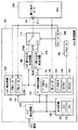
まず、図1を用いて、本実施の形態1にかかるリモコン受信システムの構成について説明する。図1は、本実施の形態1におけるリモコン受信システムの構成を示す図である。
(Embodiment 1)
Hereinafter, the remote control reception circuit and the remote control reception system according to the first embodiment will be described with reference to FIGS.
First, the configuration of the remote control reception system according to the first embodiment will be described with reference to FIG. FIG. 1 is a diagram showing a configuration of the remote control reception system according to the first embodiment.
図1において、本実施の形態1にかかるリモコン受信システムは、送信機(図示せず)から発行されたリモコン信号を受信するリモコン受信回路100と、該リモコン受信回路100の各種レジスタに任意の値を設定し、リモコン受信回路100を制御すると共に、リモコン信号をデコードするCPU190とからなるものであり、前記リモコン受信回路100は、エッジ検出回路110と、カウンタ回路120と、ヘッダ検出回路130と、データ判別回路140と、シフトレジスタ150と、ヘッダ割り込み生成回路160と、データ割り込み生成回路170と、モードレジスタ180と、スイッチ111とから構成される。そして、前記CPU190は、リモコン受信機能を実現するために必要な割り込みポートとして、前記リモコン受信回路100からの割り込み信号S111を受信する割り込みポート191を備えるものである。
In FIG. 1, the remote control receiving system according to the first embodiment includes a remote
以下、前記リモコン受信回路100の構成を詳述する。
前記エッジ検出回路110は、カウンタ回路120及び、データ判別回路140と接続されており、受信したリモコン信号の立上りエッジと立下りエッジを検出して、前記カウンタ回路120とデータ判別回路140に、その検出したエッジを通知する。
Hereinafter, the configuration of the remote
The
前記カウンタ回路120は、ロングロウカウンタ(以下、「LLC」と称す。)121と、ロングハイカウンタ(以下、「LHC」と称す。)122を有し、前記エッジ検出回路110、ヘッダ検出回路130、データ判別回路140と接続されている。そして、前記カウンタ回路120内のLLC121は、前記エッジ検出回路110からのエッジ検出通知に対して、立下りエッジでカウント値をリセットしてカウントを開始し、立上りエッジでカウントをストップするものであり、また前記カウンタ回路120内のLHC122は、立上りエッジでカウントを開始し、立下りエッジでカウントをストップしてカウンタ値をリセットするものである。
The
前記ヘッダ検出回路130は、ロングロウ閾値レジスタ(以下、「THLレジスタ」と称す。)131と、ロングハイ閾値レジスタ(以下、「THHレジスタ」と称す。)132とを有し、前記カウンタ回路120、データ判別回路140、ヘッダ割り込み生成回路160と接続されている。なお、前記ヘッダ検出回路130内のTHLレジスタ131及びTHHレジスタ132は、CPU190により値が設定可能なレジスタであり、前記THLレジスタ131には、リモコン信号のヘッダ部のロウ区間の閾値が、またTHHレジスタ132には、ヘッダ部のハイ区間の閾値が設定される。そして、前記ヘッダ検出回路130は、前記データ判別回路140、及びヘッダ割り込み生成回路160に対して、前記カウンタ回路120内のLLC121の出力値がTHLレジスタ131の設定値を上回り、且つ前記カウンタ回路120内のLHC122の出力値がTHHレジスタ132の設定値を上回っているとき、ヘッダ検出信号S130“1”を、それ以外のとき、ヘッダ検出信号“0”を出力する。
The
前記ヘッダ割り込み生成回路160は、前記ヘッダ検出回路130、及びデータ判別回路140に接続されるものであり、またスイッチ111を介して、前記CPU190の割り込みポート191に接続される。そして、前記ヘッダ割り込み生成回路160は、ヘッダ検出回路130からのヘッダ検出信号S130の立上りエッジを検出すると、前記スイッチ111に対し、ヘッダ割り込み信号S160として、1サイクルのパルスを1回出力する。
The header interrupt
前記データ判別回路140は、データ待ちフラグ141と、データ長レジスタ(以下、「DLレジスタ」と称す。)142と、データカウンタ143と、D1フラグ144と、D0フラグ145とを有し、前記カウンタ回路120、シフトレジスタ150、及びデータ割り込み生成回路170に接続されている。なお、前記ヘッダ判別回路140内のDLレジスタ142は、CPU190により値が設定可能なレジスタである。そして、前記データ判別回路140内のデータ待ちフラグ141は、ヘッダ検出信号S130の立下りエッジを検出すると“1”にセットされ、前記DLレジスタ142の設定値と前記データカウンタ143の出力値とが一致すると“0”にクリアされる。また、前記データ判別回路140内のデータカウンタ143は、前記ヘッダ検出回路130からのヘッダ検出信号S130の立上りエッジを検出するとリセットされ、シフトレジスタ150が1ビットシフトするとインクリメントされる。さらに、前記データ判別回路140内の前記D0フラグ145は、前記データ待ちフラグ141が“1”で、且つカウンタ回路120内のLHC122の出力値が1となったときに“1”にセットされ、一方、前記データ待ちフラグ141が“0”になるか、または前記エッジ検出回路110から立上りエッジが検出されるか、または前記カウンタ回路120内のLHC122の出力値が2Tを上回るか、またはヘッダ検出回路130からヘッダ検出信号S130の立上りを検出すると“0”にリセットされる。そして、前記D1フラグ144は、前記データ待ちフラグ141が“1”で、且つ前記カウンタ回路120内のLHC122の出力値が2Tを上回ったときに“1”にセットされ、一方、前記データ待ちフラグ141が“0”になるか、または前記エッジ検出回路110から立上りエッジが検出されるか、または前記ヘッダ検出回路130からのヘッダ検出信号S130の立上りエッジを検出すると“0”にリセットされるものである。さらに、データ判別回路140は、前記エッジ検出回路110から立下りエッジの検出が通知されると、その際該データ判別回路140内のD0フラグ145が“1”であったら、シフトレジスタ150を1ビットシフトさせて“0”を追加し、一方、該データ判別回路140内のD1フラグ144が“1”であったら、シフトレジスタ150を1ビットシフトさせて“1”を追加する。そして、前記データ判別回路140は、該データ判別回路140内のDLレジスタ142の設定値とデータカウンタ143の出力値とが一致すると、シフトレジスタ150にリモコン信号のデータ部に相当するデータが書き込まれたとして、データ割り込み生成回路170に対して、データ受信完了信号S140“1”を出力し、それ以外はデータ受信完了信号S140“0”を出力する。
The
前記データ割り込み生成回路170は、前記データ判別回路140と接続されており、またスイッチ111を介して、CPU190の割り込みポート191に接続される。そして、データ割り込み生成回路170は、前記データ判別回路140からのデータ受信完了信号S140の立上りエッジを検出すると、データ割り込み信号S170として、スイッチ111に対し、1サイクルのパルスを1回出力する。
The data interrupt
前記モードレジスタ180は、前記CPU190により値が設定可能なレジスタで、スイッチ111と接続される。このモードレジスタ180に“0”が設定されていると、スイッチ111は、ヘッダ割り込み生成回路160とCPU190とを接続し、一方、モードレジスタ180に“1”が設定されていると、スイッチ111は、データ割り込み生成回路160とCPU190とを接続する。
The
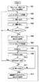
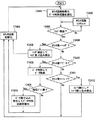
次に、図2〜図4を用いて、前述した構成を有するリモコン受信システムにおいて、リピートヘッダ型の送信機から発信されたリモコン信号を受信した場合の処理の流れを説明する。図2は、本実施の形態1におけるリモコン受信システムにおいて、リピートヘッダ型の送信機から発信されたリモコン信号を受信した場合の、リモコン受信回路及びCPUのタイミングチャートを示す図であり、図3は、リピートヘッダ型の送信機から発信されたリモコン信号を受信した場合の、本実施の形態1におけるCPU側での処理を示すフローチャートを示す図であり、図4は、リピートヘッダ型の送信機から発信されたリモコン信号を受信した場合の、本実施の形態1におけるリモコン受信回路での処理を示すフローチャートを示す図である。
Next, the flow of processing when a remote control signal transmitted from a repeat header type transmitter is received in the remote control reception system having the above-described configuration will be described with reference to FIGS. FIG. 2 is a diagram showing a timing chart of the remote control receiving circuit and the CPU when receiving a remote control signal transmitted from a repeat header type transmitter in the remote control receiving system according to the first embodiment. FIG. 4 is a flowchart illustrating processing on the CPU side in the first embodiment when a remote control signal transmitted from a repeat header type transmitter is received. FIG. It is a figure which shows the flowchart which shows the process in the remote control receiver circuit in this
まず、CPU190は、動作開始時に、ヘッダ検出回路130内のTHLレジスタ131とTHHレジスタ132、データ判別回路140内のDLレジスタ142、及びモードレジスタ180の値を設定する(F301,F302)。以下、前記各レジスタに設定される値について具体的に説明する。
First, the
前記ヘッダ検出回路130内のTHLレジスタ131の設定値は、リモコン信号のヘッダ部のロウ区間検出の閾値として用いられるので、リピートヘッダのロウ区間である16T未満の適当な値に設定する。ここでは6Tとする。また、THHレジスタ132の設定値は、リモコン信号のヘッダ部のハイ区間検出の閾値として用いられるので、リピートヘッダのハイ区間である4T未満の適当な値に設定する。ここでは3Tとする。そして、DLレジスタ143には、データ部のデータ長を設定する。ここでは32を設定する。そして、モードレジスタ180には、データ割り込み生成回路170とCPU190とが接続されるように、“1”を設定する。
Since the set value of the
以上のように各レジスタに値を設定した後、CPU190は、リモコン受信回路100からデータ割り込みが発行されるのを待つ。
リモコン受信回路100側では、動作開始時に、カウンタ回路120及びデータ判別回路140内のデータカウンタ143を初期化する(F401)。
After setting values in the respective registers as described above, the
On the remote
リモコンのボタンが押下されると、まずリモコン受信回路100にはリモコン信号のヘッダ部が到着する。ヘッダ部の最初の立下りエッジをエッジ検出回路110が検出した時刻を時刻0とすると(F402)、時刻0において、カウンタ回路120内のLLC121とLHC122とがリセットされる(F403)。このとき、データ判別回路140内のD0フラグ145、及びD1フラグは共に“0”であるため(F404,F406)、シフトレジスタ150にはデータが格納されることなく、カウンタ回路120のみがカウントアップされる(F414)。
When the remote control button is pressed, first, the remote control signal header portion arrives at the remote
そして、時刻6Tにおいて、リモコン信号のヘッダ部のロウ区間をカウントしているLLC121の出力値がTHLレジスタ131の値を上回る。
さらに、時刻16Tに、立上りエッジが検出され(F413)、カウンタ回路120内のLLC121は16Tをカウントしてストップし、LHC122がカウントを開始する(F425)。
At
Further, a rising edge is detected at
そして、時刻19Tに、前記LHC122の出力値は、ヘッダ検出回路130のTHHレジスタ132の設定値を上回る。このとき、カウンタ回路120内のLLC121の出力値は16Tでストップしているため、THLレジスタの設定値を上回っている(F415)。従って、このとき、ヘッダ検出回路130は、データ判別回路140及びヘッダ割り込み生成回路160に対して、ヘッダ検出信号S130“1”を出力する。
At
このヘッダ検出信号S130の立上りエッジを検出したデータ判別回路140は、該データ判別回路140内のデータカウンタ143をリセットし、データ待ちフラグを“1”にセットし、さらに、D0フラグ145、及びD1フラグ144を“0”にリセットする(F416)。
The
このように、本リモコン受信システムでは、ヘッダ検出回路130のTHHレジスタ132及びTHLレジスタ131に設定された値と、カウンタ回路120のLHC122及びLLC121の値とを比較するステップ(図4のF415)を、立上がりエッジ及び立下りエッジを検出するたびに行い、該F415の条件が満たされれば、リモコン信号のヘッダ部が検出されたと判断して、ヘッダ検出信号を“1”にすると共に、その際シフトレジスタ150に格納されているデータのビット数に関係なく、データ判別回路140内のデータカウンタ143をリセットするようにしている(図4のF416)。これは、本リモコン受信システムでは、データ待ち状態よりヘッダ検出を優先して処理していることを示している。つまり、本リモコン受信回路では、例えば、リモコン信号のデータ部のデータのうち30ビット受信し、残りの2ビットを待っている状況で、リモコン信号の次のヘッダ部を受信した場合、該シフトレジスタ150に格納されていた30ビットのデータを破棄し、前記次のリモコン信号のヘッダ部とデータ部に対する処理に移行される。このようにヘッダ検出を優先して行うようすれば、送信機(リモコン)と受信機(リモコン受信回路)との間を人が通過する等して、リモコンからの信号が途絶えた場合であっても、次のリモコン信号のヘッダ部を受信した場合には、リモコン受信回路が、来るはずのない残りの2ビット分のデータを待つデータ待ち状態から、CPUの処理によるのではなく自力でヘッダ部検出処理に復帰することができる。
Thus, in this remote control receiving system, the step of comparing the values set in the
そしてこの後、前記ヘッダ検出信号S130の立上りエッジを検出したヘッダ割り込み生成回路160は、ヘッダ割り込み信号S160として1サイクルのパルスを1回出力する。ただし、このとき、モードレジスタ180には“1”が設定されているので、ヘッダ割り込み生成回路160はCPU190の割り込みポート191に接続されておらず、このヘッダ割り込み信号S160は、CPU190には通知されない(F417)。
Thereafter, the header interrupt
そして、時刻24Tにおいて、エッジ検出回路110が立下りエッジを検出し(F402)、カウンタ回路120内のLLC121,LHC122がともにリセットされ(F403)、この結果、前記LLC121及びLHC122それぞれの値は、ヘッダ検出回路130のTHLレジスタ131、及びTHHレジスタ132の値を下回るため(F415)、ヘッダ検出信号S130“0”が出力される(F419)。この時、データ判別回路140のデータ待ちフラグ141には“1”がセットされているので(F420)、これによって、データ判別回路140内のD1フラグ144とD0フラグ145とがセット可能になる。
At
そして、時刻25Tにおいて、エッジ検出回路110が立上りエッジを検出し(F413)、カウンタ回路120内のLLC121は、1Tをカウントしてストップする(F425)。
At
時刻25T+1において、カウンタ回路120内のLHC122の出力値は、“1”と等しくなる。このとき、データ判別回路140内のデータ待ちフラグ141が“1”で、且つカウンタ回路120内のLHC122が“1”を達成したため(F421)、前記データ判別回路140内のD0フラグ145が“1”にセットされる(F422)。
At
次に、時刻26Tにおいて、エッジ検出回路110が立下りを検出すると(F402)、前記データ判別回路140は、D0フラグ145が“1”である状況下で、エッジ検出回路110から立下りエッジを通知されたため、前記カウンタ回路120内のLLC121,LHC122をリセットすると共に(F403)、シフトレジスタ150を1ビットシフトさせて、シフトレジスタ150に“0”を追加する(F405)。このとき、データカウンタ143はインクリメントされて“1”になる(F408)。このとき、データカウンタ143の値はまだ指定ビット数には達していないので(F409)、カウンタ回路120がカウントアップされる(F414)。
Next, when the
そして、時刻27Tにおいて、エッジ検出回路110は立上りエッジを検出し(F413)、データ判別回路140内のD0フラグ145、D1フラグ144はともに“0”にリセットされる(F425)。
At
そして、時刻27T+1において、前述した時刻25T+1の際の動作同様に、前記D0フラグ145が“1”にセットされる(F422)。
At
時刻29Tにおいて、カウンタ回路120内のLHC122は2Tをカウントし、データ待ちフラグ141が“1”で、且つカウンタ回路120内のLHC122が“2T”を達成するため(F420,421,423)、D0フラグ145が“0”、D1フラグ144が“1”にセットされる(F424)。
At
時刻30Tにおいて、エッジ検出回路110が立下りエッジを検出する(F402)。この時、カウンタ回路120内のLLC121とLHC122はリセットされる(F403)。そして、データ判別回路140は、D1フラグ144が“1”の状況下で、エッジ検出回路110から立下りエッジの検出を通知されたため(F406)、シフトレジスタ150を1ビットシフトさせ、シフトレジスタ150に“1”を追加する(F407)。このとき、データカウンタ143はインクリメントされて“2”になる(F408)。この後、該データカウンタ143の値は指定ビットには達していないので(F409)、カウンタ回路120がカウントアップする(F414)。
At
時刻31Tにおいて、エッジ検出回路110が立上りエッジを検出すると(F413)、データ判別回路140内のD0フラグ145とD1フラグ144はともに“0”にリセットされる(F425)。以下、同様にして、リモコン信号のデータ部のデータが1ビットずつシフトレジスタ150に格納されていく。
When the
そして、前述した動作を繰り返してデータ判別回路140内のデータカウンタ143の出力値がインクリメントされて“31”になった時刻を時刻Nとする時、時刻N+1Tにおいてエッジ検出回路110が立上りエッジを検出し、さらに時刻N+2Tにおいて立下りエッジを検出すると(F402)、シフトレジスタ150に“0”が追加され(F405)、データ判別回路140内のデータカウンタ143の出力値がインクリメントされて“32”となり(F408)、該データ判別回路140内のデータカウンタ143の値とDLレジスタ142の設定値とが等しくなる(F409)。このとき、前記データ判別回路140内のデータ待ちフラグ141は“0”にリセットされる(F410)と同時に、データ判別回路140からデータ割り込み生成回路170に対して、データ受信完了信号S140“1”が出力される。
Then, when the time when the output value of the data counter 143 in the
前記データ割り込み生成回路170は、前記データ受信完了信号S140の立上りを検出すると、データ割り込み信号S170として、1サイクルのパルスを1回出力する。この時、モードレジスタ180は“1”に設定されているので(F411)、スイッチ111により、前記データ割り込み生成回路170とCPU190とが接続されている。よって、CPU190の割り込みポート191に、データ割り込み信号S170である割り込み信号S111が出力され、データ割り込みが発生する(F412)。
When the data interrupt
CPU190側では、前記リモコン受信回路100からの前記割り込み信号S111を受けて(F303)、シフトレジスタ150の値を読み出す(F304)。そして、CPU190は、シフトレジスタ150から読み出したデータの正当性を評価して(F305)、該データが無効であればF302に戻り、該シフトレジスタ150から読み出したデータが有効であれば、押下されたボタンの情報を得、対応する処理を開始する(F306)。なお、このデータの正当性の評価は、押下されたリモコンボタンに対応するデータであるか否かを調べるものであり、その評価において対応するデータでなければデータが無効であると判断され、対応するデータであれば有効であると判断される。
The
この後、CPU190は、モードレジスタ180に“0”を設定し(F307)、CPU190に内蔵されたタイマ(図示せず)に任意の値Mを設定し(F308)、該タイマのダウンカウントを開始する(F309)。
Thereafter, the
そして、時刻N+3Tにおいて、再びリモコン受信回路100のエッジ検出回路110が立上りエッジを検出したとき(F413)、データ判別回路140内のD0フラグ145とD1フラグ144はともに“0”にリセットされる(F425)。そして、この時、データ判別回路140内のデータ待ちフラグ141は、既に“0”にリセットされているので(F420)、カウンタ回路120内のLHC122の出力値が1、または2Tになっても、前記データ判別回路140内のD0フラグ145とD1フラグ144は“1”にセットされず、カウンタ回路120がカウントアップされていくのみである(F414)。
At time N + 3T, when the
そして、リモコンのボタンが連続的に押下されている場合には、時刻192Tにおいてリピートヘッダ部が到着する。
When the button on the remote controller is continuously pressed, the repeat header portion arrives at
時刻192Tにおいて、エッジ検出回路110は立下りエッジを検出し(F402)、カウンタ回路120内のLLC121とLHC122がリセットされる(F403)。
At
時刻198Tにおいて、リピートヘッダ部のロウ区間をカウントしているLLC121の出力値が、ヘッダ検出回路130内のTHLレジスタ131の値を上回る。
At time 198T, the output value of the
さらに、時刻208Tに、立上りエッジが検出され(F413)、カウンタ回路120内のLLC121は16Tをカウントしてストップし、LHC122がカウントを開始する(F425)。
Furthermore, a rising edge is detected at
そして、時刻211Tに、前記LHC122の出力値は、ヘッダ検出回路130のTHHレジスタ132の設定値を上回る。このとき、カウンタ回路120内のLLC121の出力値は16Tでストップしているため、THLレジスタの設定値を上回っている(F415)。従って、ヘッダ検出回路130は、データ判別回路140及びヘッダ割り込み生成回路160に対して、ヘッダ検出信号S130“1”を出力する。
At
このヘッダ検出信号S130の立上りエッジを検出したデータ判別回路140は、該データ判別回路140内のデータカウンタ143をリセットし、またデータ待ちフラグを“1”に設定し、さらに、D0フラグ145、及びD1フラグ144を“0”にリセットする(F416)。また、前記データカウンタ143がリセットされた時点で、該データ判別回路140内のデータカウンタ143の値とDLレジスタ142の設定値とが一致しなくなるので、データ受信完了信号S140“0”が出力される。
The
一方、前記ヘッダ検出信号S130の立上りエッジを検出したヘッダ割り込み生成回路160は、ヘッダ割り込み信号S160として1サイクルのパルスを1回出力する。この時、モードレジスタ180には“0”が設定されているので(F417)、ヘッダ割り込み生成回路160は、スイッチ111によりCPU190と接続されている。よって、前記CPU190の割り込みポート191に、ヘッダ割り込み信号S160である割り込み信号S111が出力され、ヘッダ割り込みが発生する(F418,F311)。
On the other hand, the header interrupt
前記CPU190側でヘッダ割り込みが発生すると、先に押下された同じボタンが連続押下されたと判断して、該連続押下されたボタンに対応する処理を行う(F312)。そして、CPU190に内蔵されたタイマに再び任意の値Mを設定し(F308)、ダウンカウントを開始する(F309)。
When a header interrupt occurs on the
以後、リモコンのボタンが連続押下されている間は、同様にして192Tの間隔でヘッダ割り込みが発行されつづける。そして、使用者がリモコンのボタンをリリースすると、リピートヘッダ部は到着しなくなり、リモコン受信回路100はヘッダ割り込みを発行しなくなる。
そして、CPU190側では、内蔵タイマがダウンカウントを経て、アンダーフロー割り込みを発行したときに(F310)、リモコンのボタンがリリースされたと判断する。
Thereafter, while the buttons on the remote controller are continuously pressed, header interrupts are continuously issued at intervals of 192T. When the user releases the remote control button, the repeat header portion does not arrive and the remote
The
前述のようにしてリモコンのボタンのリリース判断がなされると、CPU190は、モードレジスタ180を“1”に設定し(F302)、再び、リモコン受信回路100からのデータ割り込みを待つ状態に入る。
When the remote controller button release determination is made as described above, the
このように、本実施の形態1のリモコン受信システムによれば、リモコン受信回路100に、モードレジスタ180及びスイッチ111を設け、該モードレジスタ180に設定された値に応じて、前記スイッチ111により、CPU190に出力する割り込み信号を選択して出力するようにしたので、リモコン受信機能を実現するために必要なCPU190側の割り込みポートを1つに抑えることができ、複数の割り込みポートを使用する従来手法よりも少ないCPUのリソースを使用して、リモコン信号の受信を実現することが可能となる。
Thus, according to the remote control receiving system of the first embodiment, the remote
また、本実施の形態1に係るリモコン受信システムによれば、前記リモコン受信回路100にトレーラ割り込みを発行する回路を設けず、データ割り込み信号にトレーラ割り込み信号と同様の意味を持たせるようにしたので、リモコン受信回路100の装置規模を小さくでき、且つCPU190側にはトレーラ割り込みが発行されないので、CPU190のトレーラ割り込みに対応するコードも、またその割り込みによる処理負荷も削減することができる。
In addition, according to the remote control receiving system according to the first embodiment, the remote
さらに、本実施の形態1のリモコン受信システムによれば、前記リモコン受信回路100に、前記ヘッダ割り込み生成回路160あるいはデータ割り込み生成回路170とCPU190との接続を選択するスイッチ111と、該スイッチを切り替えるモードレジスタ180とを備え、動作開始時に前記スイッチ111がCPU190と前記データ割り込み生成回路170とを接続するようにしたので、仮に、時刻0にリモコン受信回路100に入力されたヘッダがノイズによるエラーヘッダであり、該エラーヘッダにより前記リモコン受信回路100においてヘッダ割り込み信号S160が生成されたとしても、該ヘッダ割り込み信号S160はCPU190には出力されないため、CPU190側にそのエラーヘッダにより生成されたヘッダ割り込み信号S160を回避するためのコードを設けなくても、CPUにエラーヘッダによるヘッダ割り込みの発生を防止することができる。
Furthermore, according to the remote control receiving system of the first embodiment, the remote
さらに、本実施の形態1にかかるリモコン受信システムによれば、リモコン信号を受信する一連の流れのなかで、立上がりエッジ及び立下りエッジを検出するたびにヘッダ検出を確認するステップ(図4のF415)を設けるようにしたので、リモコン信号のデータ部を受信している際に何らかの原因で信号が途切れ、シフトレジスタ150に予め設定されたビット数のデータが格納される前に、次のリモコン信号のヘッダ部を受信したとしても、該ヘッダ部の検出を優先して行い、該ヘッダ部に続く新しいデータ部の待ち状態に移行することができ、これにより、リモコン信号のデータ部の一部が欠落するアクシデントが起きても、CPUに負担をかけることなく、リモコン信号の受信処理を続行することが可能となる。
Furthermore, according to the remote control reception system according to the first embodiment, the step of confirming header detection every time a rising edge and a falling edge are detected in a series of flows of receiving a remote control signal (F415 in FIG. 4). When the data portion of the remote control signal is being received, the signal is interrupted for some reason, and before the data of the preset number of bits is stored in the
さらに、本実施の形態1にかかるリモコン受信システムによれば、前記リモコン受信回路100のデータ判別回路140内に、フラグが立ち上がっているときにのみシフトレジスタ150にデータを書き込み可能とするデータ待ちフラグ141を設け、該データ待ちフラグ141は、ヘッダ検出回路130によるヘッダ部の検出後に立ち上がり、シフトレジスタ150にリモコン信号のデータ部に相当するデータが格納されてデータ受信完了信号S140が出力された後に立ち下がるものとしたので、CPU190側にデータ割り込みが発行された後に該シフトレジスタ150をホールド可能にし、当該リモコン受信回路100にデータと誤検出される波形が入力されたとしても、該シフトレジスタ150にデータが書き込まれるのを防止して、該シフトレジスタ150に格納されたリモコン信号のデータが破損することをなくすことができる。そしてこれにより、CPU190では、従来のように、データ割り込みを受信した後の前記シフトレジスタ150の読み出しにリアルタイム性が厳しく要求されなくなり、該CPU190の割り込みポート191の割り込み優先度を低く設定することができる。そして割り込みポートの優先度を低く設定できれば、CPUが本来制御しようとするシステムの処理が圧迫されなくなり、動作の遅延が生じないという効果も得られる。
Furthermore, according to the remote control reception system according to the first embodiment, the data waiting flag that allows data to be written to the
なお、前述の説明においては、リモコン受信回路100が、ボタンを連続押下された際に図22(a)に示されるようなデータを伴わないヘッダ部からなるリモコン信号を受信する場合について説明したが、当該リモコン受信回路100において受信するリモコン信号は、ボタンを連続押下された際に図22(b)に示されるような同じ波形が繰り返し続くリモコン信号であってもよい。
In the above description, a case has been described in which the remote
以下、図5及び図4を用いて、前述した構成を持つリモコン受信回路100において、繰り返しデータ型の送信機から発信されたリモコン信号を受信した場合の処理の流れを説明する。図5は、繰り返しデータ型の送信機から発信されたリモコン信号を受信した場合の、本実施の形態1におけるCPU側での処理を示すフローチャート図である。
Hereinafter, the flow of processing when the remote
まず時刻N+2Tまでの動作は、前述のシーケンスと同様であるので、省略する。
時刻N+2Tにおいて、CPU190側では、前述したように、データ割り込み信号S170である割り込み信号S111を受けて(F503)、シフトレジスタ150の値を読み出し(F504)、該シフトレジスタ150から読み出したデータの正当性を評価して、データの有効性を判断した後(F505)、押下されたボタンに対応する処理を行う(F506)。そしてこの後、リピートヘッダ部を受信した際には、前述したようにモードレジスタ180の値を“0”にセットしたが、ここでは、モードレジスタ180の値を再設定せず、“1”のままにしておく。すなわち、CPU190は、ヘッダ割り込み待ちの状態に入らず、データ割り込み待ちの状態を続ける。
First, the operation up to time N + 2T is the same as that in the above-described sequence, and is therefore omitted.
At time N + 2T, as described above, the
この後、CPU190は、内蔵されたタイマに任意の値Mを設定し(F507)、タイマのダウンカウントを開始する(F508)。
リモコンのボタンが連続的に押下されている場合、時刻192Tにおいて、繰り返しデータのヘッダ部が到着する。その後、時刻0〜N+2Tと同様の動作を経て、リモコン受信回路100からCPU190へ、再びデータ割り込みが発行される(F510)。
Thereafter, the
When the button on the remote controller is continuously pressed, the header portion of the repeated data arrives at
前記データ割り込みを受信したCPU190は、シフトレジスタ150の値を読み出し(F511)、データの有効性判断を行う(F512)。そして、データが無効と判断されればF503へ遷移し、次のデータ割り込み待ち状態となる。一方、有効であると判断されると、CPU190は、前回のデータ割り込みで取得したデータと、今回のデータ割り込みで取得したデータとが同一であるか否かを比較する(F513)。そして、これらのデータが一致していたら、リモコンボタンの連続押下中と判断して、その連続押下されたボタンに対応する処理を行い(F514)、データが一致していなければ、新たに別のボタンが押下されたものと判断して、CPU190の内蔵タイマをストップし(F515)、その新たに押下されたボタンに対応する処理を行う(F506)。
Receiving the data interrupt, the
そして、リモコンボタンがリリースされると、それ以上、CPU190にはデータ割り込みが入らなくなる。
CPU190では、内蔵タイマがダウンカウントを経て、アンダーフロー割り込みを発行したとき(F509)、リモコンのボタンがリリースされたと判断して、F503に遷移し、新たなボタン押下を待つ状態になる。
When the remote control button is released, no more data interrupts are entered into the
When the
このように本実施の形態にかかるリモコン受信システムは、繰り返しデータを送信するタイプの送信機にも対応しうる。 As described above, the remote control reception system according to the present embodiment can also be applied to a type of transmitter that repeatedly transmits data.
(実施の形態2)
以下、図6から図12を用いて、本実施の形態2にかかるリモコン受信システムについて説明する。
(Embodiment 2)
Hereinafter, the remote control reception system according to the second embodiment will be described with reference to FIGS.
前記実施の形態1においては、送信機から発行されるリモコン信号のデータ部が、ヘッダ部とデータ部とで構成される場合について説明したが、本実施の形態2においては、該リモコン信号のデータ部が、メインデータ部と、該メインデータ部の0と1を反転させた反転データ部とで構成されているものとし、また、本実施の形態2のリモコン受信回路に、前記メインデータ部と前記反転データ部とを比較した結果によって、該リモコン信号のデータ部の有効性を判断する有効性判別回路と、使用者によるリモコンボタンのリリースを検出するOFF検出回路とをさらに備えて、前記実施の形態1より、少ないCPUのリソース、及び少ないCPUの処理能力で、リモコン受信機能を実現できるようにするものである。 In the first embodiment, the case where the data portion of the remote control signal issued from the transmitter is composed of the header portion and the data portion has been described. However, in the second embodiment, the data of the remote control signal is described. Are composed of a main data portion and an inverted data portion obtained by inverting 0 and 1 of the main data portion, and the remote control receiving circuit of the second embodiment includes the main data portion and The implementation further comprises: an effectiveness determination circuit for determining the validity of the data portion of the remote control signal based on the result of comparison with the inverted data portion; and an OFF detection circuit for detecting release of the remote control button by the user. According to the first embodiment, the remote control reception function can be realized with less CPU resources and less CPU processing capacity.
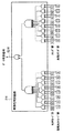
なお、本実施の形態2においては、前記リモコン信号のデータ部が、前記実施の形態1と同様32ビットであって、その32ビットのデータ部が、図6に示されるように、8ビットのカスタマコード部と、該カスタマコード部の0と1を反転させた8ビットの反転カスタマコード部と、8ビットのコマンド部と、該コマンド部の0と1を反転させた8ビットの反転コマンド部とからなる場合を例に挙げる。 In the second embodiment, the data portion of the remote control signal is 32 bits as in the first embodiment, and the 32-bit data portion is an 8-bit data as shown in FIG. A customer code part, an 8-bit inverted customer code part obtained by inverting 0 and 1 of the customer code part, an 8-bit command part, and an 8-bit inverted command part obtained by inverting 0 and 1 of the command part Take the case of
まず、図7及び図8を用いて、本実施の形態2にかかるリモコン受信システムの構成について説明する。図7は、本実施の形態2におけるリモコン受信システムの構成を示す図であり、図8は、本実施の形態2におけるリモコン受信回路内の有効性判別回路の詳細な構成を示す図である。 First, the configuration of the remote control reception system according to the second embodiment will be described with reference to FIGS. FIG. 7 is a diagram showing a configuration of the remote control reception system according to the second embodiment, and FIG. 8 is a diagram showing a detailed configuration of the validity determination circuit in the remote control reception circuit according to the second embodiment.
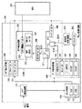
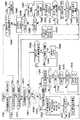
図7において、本実施の形態2に係るリモコン受信システムは、送信機(図示せず)から発行されたリモコン信号を受信するリモコン受信回路200と、該リモコン受信回路200の各種レジスタに任意の値を設定し、リモコン受信回路200を制御するCPU290とからなるものであり、リモコン受信回路200は、エッジ検出回路110と、カウンタ回路120と、ヘッダ検出回路130と、データ判別回路140と、シフトレジスタ250と、ヘッダ割り込み生成回路160と、データ割り込み生成回路270と、モードレジスタ280と、スイッチ111と、有効性判別回路210と、OFF検出回路220とを備えるものである。そして、前記CPU290は、前記リモコン受信回路200からの割り込み信号S111を受信する割り込みポート291を備えるものである。
7, the remote control receiving system according to the second embodiment has a remote
以下、前記リモコン受信回路200の構成を詳述する。本実施の形態2にかかるリモコン受信回路200は、前記実施の形態1にかかるリモコン受信回路100に、有効性判別回路210とOFF検出回路220とを追加した構成である。
Hereinafter, the configuration of the remote
前記有効性判別回路210は、シフトレジスタ250と、データ割り込み生成回路270と接続されており、前記シフトレジスタ250に格納されたリモコン信号のデータを受け、該データが有効か否かを示すデータ有効信号S210を出力する。この有効性判別回路210は、例えば図8のような構成で実現でき、前記データ有効信号S210は、前記シフトレジスタ250に格納されたデータのカスタマコード部8ビットと、反転カスタマコード部8ビットの対応する各ビットとの排他的論理和をとって、その出力8ビットの論理積をとったものと、前記シフトレジスタ250に格納されたデータのコマンド部8ビットと、反転コマンド部8ビットの対応する各ビットとの排他的論理和をとって、その出力8ビットの論理積をとったものとの論理積である。
The
前記OFF検出回路220は、前記リモコン信号の発信元である送信機(図示せず)のリモコンボタンがリリースされたか否かを検出するものであり、OFF極性レジスタ221と、OFF閾値レジスタ222と、OFFフラグレジスタ223とを有し、前記カウンタ回路120、及びモードレジスタ280と接続されている。そして、前記OFF極性レジスタ221、及びOFF閾値レジスタ222は、前記CPU290から設定可能なレジスタであり、また前記OFFフラグレジスタ223は、前記CPU290から読み出しのみ可能なレジスタである。そして、前記OFF閾値レジスタ222には、前記リモコンボタンのリリース検出に用いる閾値が設定され、前記OFF検出回路220は、前記OFF極性レジスタ221の設定値が“0”なら、カウンタ回路120内のLLC121の出力値と前記OFF閾値レジスタ222の設定値とを比較し、前記OFF極性レジスタ221の設定値が“1”なら、前記カウンタ回路120内のLHC122の出力値と前記OFF閾値レジスタ222の設定値とを比較し、それぞれの比較において、両者が等しければOFFフラグレジスタ223を“1”にセットし、一方、モードレジスタ280の設定値が“1”である状況下で、前記カウンタ回路120内のLLC121,LHC122の出力値が前記OFF閾値レジスタ222の設定値より小さければOFFフラグレジスタ223を“0”にリセットする。つまり、ここでは、前記OFFフラグレジスタ223の値が“1”であれば、前記リモコンボタンがリリースされたことを意味し、“0”であれば、リモコンボタンがリリースされておらず、連続押下されている状態にあることを意味する。
The
データ割り込み生成回路270は、前記データ判別回路140と前記有効性判別回路210と接続されており、該有効性判別回路210からのデータ有効信号S210が“1”を出力している状況下において、前記データ判別回路140からのデータ受信完了信号S140の立上りを検出すると、データ割り込み信号S270として1サイクルのパルスを1回出力する。
The data interrupt
前記モードレジスタ280は、前記スイッチ111と、前記OFF検出回路220に接続されている。そして、前記実施の形態1と同様、前記CPU290により値が設定可能なレジスタであり、このモードレジスタ280に“0”が設定されていると、スイッチ111は、ヘッダ割り込み生成回路160とCPU290とを接続し、一方、モードレジスタ280に“1”が設定されていると、スイッチ111は、データ割り込み生成回路160とCPU290とを接続する。
The
そして、CPU290は、後述する1つのタスクT110をラウンドロビンのタスクとして持っている。なお、このほかの構成については、前記実施の形態1と同様であるため、ここでは説明を省略する。
The
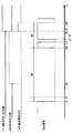
次に、図9〜図11を用いて、リピートヘッダ型の送信機から発信されたリモコン信号を受信した場合の、前述した構成を有するリモコン受信システムの処理の流れを説明する。図9は、本実施の形態2におけるリモコン受信システムが、リピートヘッダ型の送信機から発信されたリモコン信号を受信した場合のリモコン受信回路及びCPUのタイミングチャート図であり、図10(a)は、リピートヘッダ型の送信機から発信されたリモコン信号を受信した場合の、本実施の形態2におけるCPU側での処理を示すフローチャート図であり、図10(b)は、本実施の形態2におけるCPUのタスクT110の処理のフローチャート図であり、図11は、リピートヘッダ型の送信機から発信されたリモコン信号を受信した場合の、本実施の形態2におけるリモコン受信回路での処理を示すフローチャート図である。 Next, a processing flow of the remote control reception system having the above-described configuration when a remote control signal transmitted from a repeat header type transmitter is received will be described with reference to FIGS. FIG. 9 is a timing chart of the remote control receiving circuit and the CPU when the remote control receiving system according to the second embodiment receives a remote control signal transmitted from a repeat header type transmitter. FIG. FIG. 10 is a flowchart showing processing on the CPU side in the second embodiment when a remote control signal transmitted from a repeat header type transmitter is received, and FIG. 10B is a flowchart in the second embodiment. FIG. 11 is a flowchart of processing of task T110 of the CPU. FIG. 11 is a flowchart showing processing in the remote control receiving circuit according to the second embodiment when a remote control signal transmitted from a repeat header type transmitter is received. It is.
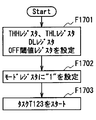
まず、CPU290は、動作開始時に初期の設定として、前記実施の形態1と同様、ヘッダ検出回路130内のTHLレジスタ131とTHHレジスタ132、データ判別回路140内のDLレジスタ143、及びモードレジスタ280に値を設定するのに加え、OFF極性レジスタ221と、OFF閾値レジスタ222に値を設定する(F1001,F1002)。以下、前記各レジスタに設定される値について具体的に述べると、前記OFF極性レジスタ221には“1”を設定し、前記OFF検出回路220内のOFF閾値レジスタ222には200Tを設定する。なお、そのほかの各レジスタには、前記実施の形態1において設定した同様の値を設定する。つまり、前記ヘッダ検出回路130内のTHLレジスタ131には6Tを設定し、THHレジスタ132には3Tを設定し、また、データ判別回路140内のDLLレジスタ143には32を設定し、モードレジスタ280には“1”を設定するものとする。
First, as an initial setting at the start of operation, the
以上のように各レジスタに値を設定した後、CPU290は、リモコン受信回路200からデータ割り込み信号S270が発行されるのを待つ。
After setting the values in the respective registers as described above, the
また、リモコン受信回路200側では、動作開始時に、カウンタ回路120及びデータ判別回路140内のデータカウンタ143を初期化する(F1101)。
On the remote
そして、リモコンのボタンが押下されると、まずリモコン受信回路200にはリモコン信号のヘッダ部が到着する。ヘッダ部の最初の立下りエッジをエッジ検出回路110が検出した時刻を時刻0とすると(F1102)、時刻0において、カウンタ回路120内のLLC121とLHC122とがリセットされる(F1103)。このとき、データ判別回路140内のD0フラグ145、及びD1フラグ144は共に“0”であるため(F1104,F1106)、シフトレジスタ250にはデータが格納されることなく、カウンタ回路120のみがカウントアップされる(F1115)。
When the remote control button is pressed, the remote control signal header portion first arrives at the remote
そして、時刻6Tにおいて、リモコン信号のヘッダ部のロウ区間をカウントしているLLC121の出力値がTHLレジスタ131の値を上回る。
At
さらに、時刻16Tに、立上りエッジが検出され(F1114)、カウンタ回路120内のLLC121は16Tをカウントしてストップし、LHC122がカウントを開始する(F1130)。
Further, a rising edge is detected at
そして、時刻19Tに、前記LHC122の出力値は、ヘッダ検出回路130のTHHレジスタ132の設定値を上回る。このとき、カウンタ回路120内のLLC121の出力値は16Tでストップしているため、THLレジスタ131の設定値を上回っている(F1116)。従って、このとき、ヘッダ検出回路130は、データ判別回路140及びヘッダ割り込み生成回路160に対して、ヘッダ検出信号S130“1”を出力する。
At
このヘッダ検出信号S130の立上りエッジを検出したデータ判別回路140は、該データ判別回路140内のデータカウンタ143をリセットし、データ待ちフラグを“1”にセットし、さらに、D0フラグ145、及びD1フラグ144を“0”にリセットする(F1117)。また、前記ヘッダ検出信号S130の立上りエッジを検出したヘッダ割り込み生成回路160は、ヘッダ割り込み信号S160として1サイクルのパルスを1回出力する。ただし、このとき、モードレジスタ280には“1”が設定されているので、ヘッダ割り込み生成回路160はCPU290の割り込みポート291に接続されておらず、このヘッダ割り込み信号S160は、CPU290には通知されない(F1118)。
The
そして、時刻24Tにおいて、エッジ検出回路110が立下りエッジを検出し(F1102)、カウンタ回路120内のLLC121,LHC122がともにリセットされ(F1103)、この結果、前記LLC121及びLHC122それぞれの値は、ヘッダ検出回路130のTHLレジスタ131、及びTHHレジスタ132の値を下回るため(F1116)、ヘッダ検出信号S130“0”が出力される(F1120)。そしてこの後、前記OFF検出回路220内のOFF極性レジスタ221に“1”が設定されているので、該OFF検出回路220において、前記カウンタ回路120内のLHC122の値と、前記OFF閾値レジスタ222の設定値とが比較され、この時、前記カウンタ回路120内のLHC122の値は“3T”で、モードレジスタ280は“0”がセットされているので(F1121,F1122)、OFFフラグレジスタは“0”にリセットされない。さらにこの時、前記データ判別回路140内のデータ待ちフラグ141は“1”にセットされているので(F1124)、これによって、データ判別回路140内のD1フラグ144とD0フラグ145とがセット可能になる。
At
そして、時刻25Tにおいて、エッジ検出回路110が立上りエッジを検出し(F1114)、カウンタ回路120内のLLC121は、1Tをカウントしてストップする(F1130)。
At
時刻25T+1において、カウンタ回路120内のLHC122の出力値は、“1”と等しくなる。このとき、データ判別回路140内のデータ待ちフラグ141が“1”で、且つカウンタ回路120内のLHC122が“1”を達成したため(F1125)、前記データ判別回路140内のD0フラグ145が“1”にセットされる(F1126)。
At
次に、時刻26Tにおいて、エッジ検出回路110が立下りを検出すると(F1102)、前記データ判別回路140は、D0フラグ145が“1”である状況下で、エッジ検出回路110から立下りエッジを通知されたため(F1102)、前記カウンタ回路120内のLLC121,LHC122をリセットすると共に(F1103)、シフトレジスタ250を1ビットシフトさせて、シフトレジスタ250に“0”を追加する(F1105)。このとき、データカウンタ143はインクリメントされて“1”になる(F1108)。該データカウンタ143の値は指定ビット数には達していないので(F1109)、カウンタ回路120がカウントアップされる(F1115)。
Next, when the
そして、時刻27Tにおいて、エッジ検出回路110は立上りエッジを検出し(F1114)、データ判別回路140内のD0フラグ145、D1フラグ144はともに“0”にリセットされる(F1130)。
At
そして、時刻27T+1において、前述した時刻25T+1の際の動作同様に、前記D0フラグ145が“1”にセットされる(F1126)。
At
時刻29Tにおいて、カウンタ回路120内のLHC122は2Tをカウントし、データ待ちフラグ141が“1”で、且つカウンタ回路120内のLHC122が“2T”を達成したため(F1124,1125,1127)、D0フラグ145が“0”、D1フラグ144が“1”にセットされる(F1128)。
At
時刻30Tにおいて、エッジ検出回路110が立下りエッジを検出する(F1102)。この時、カウンタ回路120内のLLC121とLHC122はリセットされる(F1103)。そして、データ判別回路140は、D1フラグ144が“1”の状況下で、エッジ検出回路110から立下りエッジの検出を通知されたため(F1104)、シフトレジスタ250を1ビットシフトさせ、シフトレジスタ250に“1”を追加する(F1107)。このとき、データカウンタ143はインクリメントされて“2”になる(F1108)。この後、該データカウンタ143の値は指定ビットには達していないので(F1109)、カウンタ回路120がカウントアップする(F1115)。
At
時刻31Tにおいて、エッジ検出回路110が立上りエッジを検出すると(F1114)、データ判別回路140内のD0フラグ145とD1フラグ144はともに“0”にリセットされる(F1130)。以下、同様にして、リモコン信号のデータ部のデータが1ビットずつシフトレジスタ250に格納されていく。
When the
そして、前述した動作を繰り返してデータ判別回路140内のデータカウンタ143の出力値がインクリメントされて“31”になった時刻を時刻Nとする時、時刻N+1Tにおいてエッジ検出回路110が立上りエッジを検出し、さらに時刻N+2Tにおいて立下りエッジを検出すると(F1102)、シフトレジスタ250に“0”が追加され(F1105)、データ判別回路140内のデータカウンタ143の出力値がインクリメントされて“32”となり(F1108)、該データ判別回路140内のデータカウンタ143の値と、DLレジスタ142の設定値とが等しくなる(F1109)。このとき、前記データ判別回路140内のデータ待ちフラグ141は“0”にリセットされ(F1110)、前記データ判別回路140からデータ受信完了信号S140が出力されると同時に、前記データ有効性判別回路210において、前記シフトレジスタ250に格納されたデータの有効性が判断される。
Then, when the time when the output value of the data counter 143 in the
例えば、前記シフトレジスタ250内のデータが、受信時のノイズ等によって1ビットだけ破損していると、前記データ有効性判別回路210からはデータ有効信号S210“0”が出力され(F1112)、データ割り込み生成回路270は、前記データ判別回路140からのデータ受信完了信号S140の立上りエッジを検出しても、データ割り込み信号S270を出力しない。これにより、前記CPU290は、エラーデータによるデータ割り込みを受けなくすることができ、使用者がリモコンボタンを新たに押しなおすことによって、当該リモコン受信回路200がデータを伴う新たなリモコン信号を受信するまで、前記CPU290は、該リモコン受信回路200からの無駄な割り込みを受けることなく、動作することができる。
For example, if the data in the
また、前記有効性判別回路210において、前記シフトレジスタ250に格納されたデータが有効であると判断された場合、前記有効性判別回路210は、データ有効信号S210 “1”を出力する。そして、前記データ割り込み生成回路270は、該有効性判別回路210からデータ有効信号S210“1”が出力されている状況下において、前記データ判別回路140からのデータ受信完了信号S140の立上りを検出すると、データ割り込み信号S270として1サイクルのパルスを1回出力する。この時、モードレジスタ280は“1”に設定されているので(F1111)、スイッチ111により、前記データ割り込み生成回路270とCPU290とが接続されている。よって、CPU290の割り込みポート291に、データ割り込み信号S270である割り込み信号S111が出力され、データ割り込みが発生する(F1113)。
When the
CPU290側では、前記リモコン受信回路200からのデータ割り込み信号S270である割り込み信号S111を受けると(F1003)、シフトレジスタ250から読み出したデータの正当性を評価し(F1005)、該データが無効であればF1002に戻り、該シフトレジスタ250から読み出したデータが有効であれば、押下されたボタンの情報を得、該ボタンに対応する処理を開始する(F1006)。なお、このデータの正当性の評価は、リモコンボタンに対応するデータであるか否かを調べるものであり、その評価において、対応するデータがなければデータが無効であると判断され、対応するデータがあれば有効であると判断される。
When the
この後、前記CPU290は、モードレジスタ280に“0”を設定し(F1007)、さらにCPU290は、ラウンドロビンのタスクとして、図10(b)に示されるタスクT110を起動する(F1008)。
Thereafter, the
以後、リモコンボタンが連続押下されている間は、192Tの間隔でリピートヘッダが到着し、ヘッダ割り込みが発行されつづける。CPU290は、ヘッダ割り込みが通知されると(F1010)先に押下されたボタンが連続押下されたと判断し、その連続押下されたボタンに対応する処理を行う(F1011)。
Thereafter, while the remote control button is continuously pressed, a repeat header arrives at an interval of 192T, and a header interrupt continues to be issued. When notified of the header interrupt (F1010), the
この間、図10(b)に示すように、CPU290内に設けられたタスクT110は実行順序が来るたびに(F1018)、OFFフラグレジスタ223を読み出すが(F1028)、該OFFフラグレジスタの値が“0”であれば(F1038)、再びラウンドロビンのキューに入る(F1018)。
During this time, as shown in FIG. 10B, the task T110 provided in the
そして、使用者がリモコンボタンをリリースすると、リピートヘッダ部はCPU290側に到着しなくなり、リモコン信号には長いハイ区間が現れる。そして、最後のリピートヘッダから200T後、LHC122の出力値は200Tに達し(F1121)、OFFフラグレジスタ223は“1”にセットされる(F1129)。
When the user releases the remote control button, the repeat header portion does not arrive at the
やがて、CPU290側では、タスクT110によって、OFFフラグレジスタ223から“1”が読み出されると(F1028,1038)、CPU290側ではタスクT110が終了する(F1009)。このタスクT110の終了により、CPU290はリモコンボタンのリリースを検知し、モードレジスタ280に“1”を設定し(F1010)、再び、前記リモコン受信回路200からのデータ割り込みを待つ状態になる。
Eventually, when “1” is read from the
このように、本実施の形態2のリモコン受信システムによれば、前記リモコン受信回路200で受信するリモコン信号のデータ部が、メインデータ部と、該メインデータ部の0と1を反転させた反転データ部とで構成されている場合に、該リモコン受信回路200に前記メインデータ部と前記反転データ部とを比較することで該リモコン信号のデータ部の有効性を判断する有効性判別回路210を備え、データ割り込み生成回路270が、該有効性判別回路210において前記リモコン信号のデータが有効であると判断され、且つ前記データ判別回路140からデータ受信完了信号S140が出力されたときに、データ割り込み信号S270を出力するようにしたので、CPU290側にエラーデータによる不要なデータ割り込み信号が発行されなくなり、これにより、リモコン受信機能に使用するCPU290の処理能力をさらに軽減することができる。
Thus, according to the remote control receiving system of the second embodiment, the data portion of the remote control signal received by the remote
さらに、本実施の形態2のリモコン受信システムによれば、前記リモコン受信回路200にリモコンボタンのリリースを検出するOFF検出回路220を備えると共に、CPU290が、押下されたリモコンボタンに対応する処理を行った後に開始されるラウンドロビンのタスクT110のコードを持つようにし、前記OFF検出回路220によって検出されたリモコンボタンがリリースされたか否かの判断結果を、CPU290が前記タスクT110のフローにおいて読み出すようにしたので、CPU290側において、内蔵タイマを用いることなく使用者がリモコンボタンをリリースしたことを検知することが可能となり、リモコン受信機能に使用するCPU290のリソースをさらに少なくすることができる。
Furthermore, according to the remote control reception system of the second embodiment, the remote
さらに、前述の説明においては、リモコン受信回路200が、ボタンを連続押下された際に図22(a)に示されるようなデータを伴わないリピートヘッダ部からなるリモコン信号を受信する場合について説明したが、当該リモコン受信回路200において受信するリモコン信号は、ボタンを連続押下された際に図22(b)に示されるような同じ波形が繰り返し続くリモコン信号であってもよい。
Furthermore, in the above description, a case has been described where the remote
以下、図11及び図12を用いて、前述した構成を持つリモコン受信回路200において、繰り返しデータ型の送信機から発信されたリモコン信号を受信した場合の処理の流れを説明する。図12(a)は、繰り返しデータ型のリモコン信号を受信した場合の、本実施の形態2におけるCPU側での処理を示すフローチャート図であり、図12(b)は、本実施の形態2におけるCPUのタスクT110の処理のフローチャート図である。
Hereinafter, the flow of processing when the remote
まず、時刻N+2Tまでの動作は、前述のシーケンスと同様であるので、省略する。
時刻N+2Tにおいて、CPU290側では、前述したように、前記有効性判別回路210により有効と判断されたデータを読み出して(F1204)、押下されたリモコンボタンに対応する処理をする(F1206)。そしてこの後、リピートヘッダ部を受信した際には、前述したようにモードレジスタ280の値を“0”にセットしたが、ここでは、モードレジスタ280の値を再設定せず、“1”のままでタスクT110を起動する(F1207)。
First, since the operation up to time N + 2T is the same as the above-described sequence, the description is omitted.
At time N + 2T, as described above, the
リモコンボタンが連続的に押下されている場合、時刻192Tにおいて、繰り返しデータのヘッダ部が到着する。その後、時刻0〜N+2Tと同様の動作を経て、リモコン受信回路200からCPU290へ、再びデータ割り込みが発行される(F1209)。
When the remote control button is continuously pressed, the header portion of the repeated data arrives at
前記データ割り込みを受信したCPU290は、シフトレジスタ250の値を読み出し(F1209)、データの有効性の判断する(F1211)。そして、データが無効と判断されればF1203へ遷移し、次のデータ割り込み待ち状態となる。一方、有効であると判断されると、CPU290は、前回のデータ割り込みで取得したデータと、今回のデータ割り込みで取得したデータとが同一であるか否かを比較する(F1212)。そして、これらのデータが一致していたら、リモコンボタンの連続押下中と判断して、その連続押下されたボタンに対応する処理を行い(F1213)、データが一致していなければ、タスクT110を停止し(F1214)、新たに別のボタンが押下されたものと判断して、その新たに押下されたボタンに対応する処理を行う(F1206)。
The
リモコンボタンが連続押下される限り、192Tおきにデータ割り込みが発生し、同一のデータがF1210で読み出される。この間、図12(b)に示すように、CPU290が持つタスクT110は実行順序が来るたびに(F1217)、OFFフラグレジスタ223の値を読み出すが(F1227)、該OFFフラグレジスタ223の値が“0”であれば(F1237)、再びラウンドロビンのキューに入る(F1208)。
As long as the remote control button is continuously pressed, a data interrupt occurs every 192T, and the same data is read in F1210. During this time, as shown in FIG. 12B, the task T110 of the
そして、使用者がリモコンボタンをリリースすると、リピートヘッダ部はCPU290側に到着しなくなり、リモコン信号には長いハイ区間が現れる。そして、最後のリピートヘッダから200T後、LHC122の出力値は200Tに達し(F1121)、OFFフラグレジスタ223は“1”にセットされる(F1129)。
When the user releases the remote control button, the repeat header portion does not arrive at the
やがて、CPU290側では、タスクT110によって、OFFフラグレジスタ223から“1”が読み出されると(F1227,1237)、CPU290側ではタスクT110が終了する(F1208)。このタスクT110の終了により、CPU290はリモコンボタンのリリースを検知し、F1203に遷移して新たなボタン押下を待つ状態になる。
Eventually, when “1” is read from the
このように本実施の形態にかかるリモコン受信システムは、繰り返しデータを送信するタイプの送信機にも対応しうる。 As described above, the remote control reception system according to the present embodiment can also be applied to a type of transmitter that repeatedly transmits data.
(実施の形態3)
以下、図13から図17を用いて、本実施の形態3にかかるリモコン受信システムについて説明する。
(Embodiment 3)
Hereinafter, the remote control reception system according to the third embodiment will be described with reference to FIGS. 13 to 17.
本実施の形態3のリモコン受信システムにおいては、前記実施の形態2と同様、該リモコン信号のデータ部が、メインデータ部と、該メインデータ部の0と1を反転させた反転データ部とで構成されているものとし、また、本実施の形態3のリモコン受信回路には、ヘッダ割り込み生成回路、及びデータ割り込み生成回路を設けず、該リモコン受信回路からCPUに割り込みが発行されないようにしてCPUの割り込みポートを全く使わず、CPUが持つラウンドロビンタスクのみでリモコン受信機能を実現するものである。さらに、前記実施の形態2では、リモコンボタンのリリースをカウンタ回路120のレジスタの値とOFF検出回路220内のOFF閾値レジスタ222の設定値とを比較することで判断していたが、本実施の形態3では、OFF検出回路内にある値まで常にカウントアップするOFFカウンタを設け、該OFFカウンタの値とOFF閾値レジスタの値を比較することで、ノイズによってリモコンボタンのリリースの検出が遅延されるのを回避できるようにするものである。
In the remote control reception system according to the third embodiment, as in the second embodiment, the data portion of the remote control signal includes a main data portion and an inverted data portion obtained by inverting 0 and 1 of the main data portion. It is assumed that the remote control receiving circuit of the third embodiment is not provided with a header interrupt generation circuit and a data interrupt generation circuit, so that no interrupt is issued from the remote control reception circuit to the CPU. The remote control reception function is realized only by the round robin task of the CPU without using any interrupt port. Further, in the second embodiment, the release of the remote control button is determined by comparing the register value of the
なお、本実施の形態3においては、送信機(図示せず)から発行されるリモコン信号のデータ部が、前記実施の形態2と同様、図6に示されるような、8ビットのカスタマコード部と、該カスタマコードの0と1を反転させた8ビットの反転カスタマコード部と、8ビットのコマンド部と、該コマンド部の0と1を反転させた8ビットの反転コマンド部とからなる場合を例に挙げる。 In the third embodiment, the data portion of the remote control signal issued from the transmitter (not shown) is an 8-bit customer code portion as shown in FIG. 6 as in the second embodiment. And an 8-bit inverted customer code portion obtained by inverting 0 and 1 of the customer code, an 8-bit command portion, and an 8-bit inverted command portion obtained by inverting 0 and 1 of the command portion. Take as an example.
まず、図13を用いて、本実施の形態3にかかるリモコン受信回路の構成について説明する。図13は、本実施の形態3におけるリモコン受信システムの構成を示す図である。 First, the configuration of the remote control receiving circuit according to the third embodiment will be described with reference to FIG. FIG. 13 is a diagram illustrating a configuration of the remote control reception system according to the third embodiment.
図13において、本実施の形態3に係るリモコン受信システムは、送信機(図示せず)から発行されたリモコン信号を受信するリモコン受信回路300と、該リモコン受信回路300の各種レジスタに任意の値を設定し、リモコン受信回路300を制御するCPU390とからなるものであり、リモコン受信回路300は、エッジ検出回路110と、カウンタ回路120と、ヘッダ検出回路130と、データ判別回路140と、シフトレジスタ250と、モードレジスタ180と、スイッチ311と、ANDゲート312と、OFF検出回路320と、データ/ヘッダフラグレジスタ(以下、「DHフラグレジスタ」と称す。)330と、を備えるものである。そして、前記CPU390には、前記リモコン受信回路300からの割り込みが発行されることがないので、割り込みポートが設けられていない。
In FIG. 13, the remote control receiving system according to the third embodiment has a remote
以下、前記リモコン受信回路300の構成を詳述する。本実施の形態3にかかるリモコン受信回路300は、前記実施の形態2にかかるリモコン受信回路200から、データ割り込み生成回路と、ヘッダ割り込み生成回路とを削除し、DHフラグレジスタ330を追加した構成となっている。
Hereinafter, the configuration of the remote
DHフラグレジスタ330は、スイッチ311と、OFF検出回路320と接続されており、CPU390から読み出しと書き込みが可能なレジスタである。そして、前記DHフラグレジスタ330は、前記スイッチ311からのOFFカウントリセット信号S311を受信し、該OFFカウントリセット信号S311の立上りを検出すると“1”がセットされ、CPU390に“0”を書き込まれることによってのみ、“0”にリセットされるものである。
The
前記スイッチ311は、ANDゲート312を介してデータ判別回路140と、有効性データ判別回路210と接続され、ヘッダ検出回路130と、DHフラグレジスタ330と、モードレジスタ180とが接続される。前記スイッチ311は、前記モードレジスタ180の設定値が“1”ならば、前記データ判別回路140からのデータ受信完了信号S140と前記有効性判別回路210からのデータ有効信号S210との論理積を前記DHフラグレジスタ330に出力し、一方、前記モードレジスタ180の設定値が“0”ならば、前記ヘッダ検出回路130からのヘッダ検出信号S130を前記DHフラグレジスタ330に出力するものである。
The
前記OFF検出回路320は、DHフラグレジスタ330と接続され、OFF閾値レジスタ222と、OFFカウンタ321と、ONフラグレジスタ323とを有するものである。そして、前記OFFカウンタ321は、常にカウントアップしており、前記DHフラグレジスタ330の値が“1”になると、リセットされる。また、前記ONフラグレジスタ323は、DHフラグレジスタ330の値が“1”になると“1”にセットされ、OFFカウンタ321の出力値とOFF閾値レジスタ222の設定値とが等しくなると“0”にリセットされる。
The
そして、前記CPU390は、後述する2つのタスクT120,T121をラウンドロビンのタスクとして持っている。なお、このほかの前記実施の形態において説明したものと同じ番号が付されたものについては、前述した実施の形態において説明したものと同じであるため、ここでは説明を省略する。
The
次に、図14〜図16を用いて、リピートヘッダ型の送信機から発信されたリモコン信号を受信した場合の、前述した構成を有するリモコン受信システムの処理の流れを説明する。図14は、本実施の形態3におけるリモコン受信システムが、リピートヘッダ型の送信機から発信されたリモコン信号を受信した場合のリモコン受信回路及びCPUのタイミングチャート図であり、図15(a)は、リピートヘッダ型の送信機から発信されたリモコン信号を受信した場合の、本実施の形態3におけるCPU側での処理を示すフローチャート図であり、図15(b)は、本実施の形態3におけるCPUのタスクT120の処理のフローチャート図であり、図15(c)は、本実施の形態3におけるCPUのタスクT121の処理のフローチャート図であり、図16は、リピートヘッダ型の送信機から発信されたリモコン信号を受信した場合の、本実施の形態3におけるリモコン受信回路での処理を示すフローチャート図である。 Next, a processing flow of the remote control reception system having the above-described configuration when a remote control signal transmitted from a repeat header type transmitter is received will be described with reference to FIGS. FIG. 14 is a timing chart of the remote control receiving circuit and the CPU when the remote control receiving system according to the third embodiment receives a remote control signal transmitted from a repeat header type transmitter. FIG. FIG. 15 is a flowchart showing processing on the CPU side in the third embodiment when a remote control signal transmitted from a repeat header type transmitter is received, and FIG. 15B is a flowchart in the third embodiment. FIG. 15C is a flowchart of the process of CPU task T121 in the third embodiment, and FIG. 16C is a flowchart of the process of CPU task T120, and FIG. 16 is transmitted from a repeat header type transmitter. FIG. 11 is a flowchart showing processing in a remote control receiving circuit in the third embodiment when a remote control signal is received.
まず、CPU390は、動作開始時に初期の設定として、前記実施の形態2と同様、ヘッダ検出回路130内のTHLレジスタ131とTHHレジスタ132、データ判別回路140内のDLレジスタ143、前記OFF検出回路320内のOFF閾値レジスタ222及びモードレジスタ180に値を設定する(F1501,F1502)。以下、前記各レジスタに設定される値について具体的に述べると、前記ヘッダ検出回路130内のTHLレジスタ131には6Tを設定し、THHレジスタ132には3Tを設定し、データ判別回路140内のDLLレジスタ143には32を設定し、OFF検出回路140内のOFF閾値レジスタ222には200Tを設定し、また、モードレジスタ180には“1”を設定するものとする。
First, as an initial setting at the start of operation, the
以上のように各レジスタに値を設定した後、CPU390は、ラウンドロビンのタスクとしてタスクT120を開始する(F1503)。
After setting the values in the respective registers as described above, the
また、リモコン受信回路300側では、動作開始時に、カウンタ回路120及びデータ判別回路140内のデータカウンタ143を初期化する(F1601)。
On the remote
リモコンのボタンが押下されると、まずリモコン受信回路300にはリモコン信号のヘッダ部が到着する。ヘッダ部の最初の立下りエッジをエッジ検出回路110が検出した時刻を0とすると(F1602)、時刻0において、カウンタ回路120内のLLC121とLHC122とがリセットされる(F1603)。このとき、データ判別回路140内のD0フラグ145、及びD1フラグは共に“0”であるため(F1604,F1606)、シフトレジスタ250にはデータが格納されることなく、カウンタ回路120のみがカウントアップされる(F1605)。
When a button on the remote control is pressed, first, a remote control signal header portion arrives at the remote
そして、時刻6Tにおいて、リモコン信号のヘッダ部のロウ区間をカウントしているLLC121の出力値がTHLレジスタ131の値を上回る。
At
さらに、時刻16Tに、立上りエッジが検出され(F1614)、カウンタ回路120内のLLC121は16Tをカウントしてストップし、LHC122がカウントを開始する(F1627)。
Further, a rising edge is detected at
そして、時刻19Tに、前記LHC122の出力値は、ヘッダ検出回路130のTHHレジスタ132の設定値を上回る。このとき、カウンタ回路120内のLLC121の出力値は16Tでストップしているため、THLレジスタ131の設定値を上回っている(F1616)。このとき、前記実施の形態では、前記ヘッダ検出回路130がデータ判別回路140及びヘッダ割り込み生成回路160に対して、ヘッダ検出信号S130“1”を出力し、ヘッダ割り込み生成回路160の動作が発生したが、本実施の形態3では、以下の動作が発生する。
At
すなわち、前記ヘッダ検出回路130から、データ判別回路140及びスイッチ311に対してヘッダ検出信号S130“1”が出力され、このヘッダ検出信号S130の立ち上がりエッジを検出した前記データ判別回路140は、データ待ちフラグを“1”にセットし、前記データカウンタ143をリセットし、さらにD1フラグ144及び、D0フラグ145を“0”にリセットする(F1617)。また、前記ヘッダ検出回路130からのヘッダ検出信号S130“1”は、スイッチ311に伝えられるが、このときモードレジスタ180が“1”に設定されているため(F1618)、前記ヘッダ検出回路130はDHフラグレジスタ330とは接続されないため、このヘッダ検出信号S130の立ち上がりは、DHフラグレジスタ330には伝えられず、ONフラグレジスタ323は“0”のままであり、この結果OFFカウンタ321もリセットされない。
That is, a header detection signal S130 “1” is output from the
そして、時刻24Tにおいて、エッジ検出回路110が立下りエッジを検出し(F1602)、カウンタ回路120内のLLC121,LHC122がともにリセットされ(F1603)、この結果、前記LLC121及びLHC122それぞれの値は、ヘッダ検出回路130のTHLレジスタ131、及びTHHレジスタ132の値を下回るため(F1616)、ヘッダ検出信号S130“0”が出力される(F1620)。そして、OFF検出回路320内のOFFカウンタ321の値とOFF閾値レジスタ222との値が比較される(F1621)。そして、この時、データ判別回路140のデータ待ちフラグ141には“1”がセットされているので(F1622)、これによって、データ判別回路140内のD1フラグ144とD0フラグ145とがセット可能になる。
At
そして、時刻25Tにおいて、エッジ検出回路110が立上りエッジを検出し(F1614)、カウンタ回路120内のLLC121は、1Tをカウントしてストップする(F1628)。
At
時刻25T+1において、カウンタ回路120内のLHC122の出力値は、“1”と等しくなる。このとき、データ判別回路140内のデータ待ちフラグ141が“1”で、且つカウンタ回路120内のLHC122が“1”を達成したため(F1623)、前記データ判別回路140内のD0フラグ145が“1”にセットされる(F1624)。
At
次に、時刻26Tにおいて、エッジ検出回路110が立下りを検出すると(F1602)、前記データ判別回路140は、D0フラグ145が“1”である状況下で、エッジ検出回路110から立下りエッジを通知されたため、前記カウンタ回路120内のLLC121,LHC122をリセットすると共に(F1603)、シフトレジスタ250を1ビットシフトさせて、シフトレジスタ250に“0”を追加する(F1605)。このとき、データカウンタ143はインクリメントされて“1”になる(F1608)。該データカウンタ143の値は指定ビット数には達していないので(F1609)、カウンタ回路120がカウントアップされる(F1615)。
Next, when the
そして、時刻27Tにおいて、エッジ検出回路110は立上りエッジを検出し(F1614)、データ判別回路140内のD0フラグ145、D1フラグ144はともに“0”にリセットされる(F1628)。
At
そして、時刻27T+1において、前述した時刻25T+1の際の動作同様に、前記D0フラグ145が“1”にセットされる(F1624)。
At
時刻29Tにおいて、カウンタ回路120内のLHC122は2Tをカウントし、データ待ちフラグ141が“1”で、且つカウンタ回路120内のLHC122が“2T”を達成したため(F1622,1623,1625)、D0フラグ145が“0”、D1フラグ144が“1”にセットされる(F1626)。
At
時刻30Tにおいて、エッジ検出回路110が立下りエッジを検出する(F1602)。この時、カウンタ回路120内のLLC121とLHC122はリセットされる(F1603)。そして、データ判別回路140は、D1フラグ144が“1”の状況下で、エッジ検出回路110から立下りエッジの検出を通知されたため(F1606)、シフトレジスタ250を1ビットシフトさせ、シフトレジスタ250に“1”を追加する(F1607)。このとき、データカウンタ143はインクリメントされて“2”になる(F1608)。この後、該データカウンタ143の値は指定ビットには達していないので(F1609)、カウンタ回路120がカウントアップする(F1615)。
At
時刻31Tにおいて、エッジ検出回路110が立上りエッジを検出すると(F1614)、データ判別回路140内のD0フラグ145とD1フラグ144はともに“0”にリセットされる(F1628)。以下、同様にして、リモコン信号のデータ部のデータが1ビットずつシフトレジスタ250に格納されていく。
When the
そして、前述した動作を繰り返してデータ判別回路140内のデータカウンタ143の出力値がインクリメントされて“31”になった時刻を時刻Nとする時、時刻N+1Tにおいてエッジ検出回路110が立上りエッジを検出し、さらに時刻N+2Tにおいて立下りエッジを検出すると(F1602)、シフトレジスタ250に“0”が追加され(F1605)、データ判別回路140内のデータカウンタ143の出力値がインクリメントされて“32”となり(F1608)、該データ判別回路140内のデータカウンタ143の値とDLレジスタ142の設定値とが等しくなる(F1609)。このとき、前記データ判別回路140内のデータ待ちフラグ141は“0”にリセットされる(F1610)と同時に、データ判別回路140からデータ割り込み生成回路170に対して、データ受信完了信号S140“1”が出力される。さらに、このとき、モードレジスタ180が“1”であるので(F1611)、スイッチ311はデータ判別回路140からのデータ受信完了信号S140と有効性判別回路S210からのデータ有効信号S210との論理積のほうを選択している。そして、この後、有効性判別回路210にて、前記シフトレジスタ250に格納されたデータが有効か否かを判断し(F1612)、データが有効と判断されれば、データ有効信号S210“1”が出力され、DHフラグレジスタ330には、データ受信完了信号S140“1”とデータ有効信号S210“1”との論理積“1”であるOFFカウントリセット信号S311が出力され、これによりDHフラグレジスタ330が“1”にセットされ、さらに、DHフラグレジスタ330の立上りエッジを前記OFF検出回路320が検出するので、該OFF検出回路320内のOFFカウンタ321がリセットされ、ONフラグレジスタ323が“1”にセットされる(F1613)。
Then, when the time when the output value of the data counter 143 in the
前述のF1613が発生するまでの間、CPU390側では、タスクT120が実行されており、実行順序が来るたびにDHフラグレジスタ330の値を読み出すが(F1505)、該DHフラグレジスタ330の値が“0”であるため(F1506)、再びラウンドロビンのキューに入る(F1504)。
Until the aforementioned F1613 occurs, the task T120 is executed on the
そして、前記F1613発生後、CPU390側では、やがてタスクT120によってDHフラグレジスタ330から“1”が読み出される(F1506)。そして、CPU390は、シフトレジスタ250の値を読み出し(F1507)、該シフトレジスタ250から読み出したデータの正当性を評価して(F1508)、該データが有効でなければ再びラウンドロビンのキューに入り(F1504)、一方該データが有効であれば、押下されたボタンの情報を得、対応する処理を開始する(F1509)。
After the occurrence of F1613, on the
そして、CPU390は、モードレジスタ180に“0”を設定し(F1510)、DHフラグレジスタ330を“0”にリセットした後(F1511)、タスクT121をラウンドロビンのタスクとして起動して(F1512)、現在実行中のタスクT120をラウンドロビンタスクから外す。
The
そして、時刻N+3T以降は、データ判別回路140内のデータ待ちフラグ141が“0”にセットされていることから、カウンタ回路120内のLHC122の出力値が1、または2Tになっても、前記データ判別回路140内のD0フラグ145とD1フラグ144は“1”にセットされず、カウンタ回路120がカウントアップされていくのみである。
After time N + 3T, the
そして、リモコンボタンが連続押下されている場合には、時刻192Tにおいてリピートヘッダ部が到着する。
If the remote control button is continuously pressed, the repeat header portion arrives at
時刻192Tにおいて、エッジ検出回路110は立下りエッジを検出し(F1602)、カウンタ回路120内のLLC121とLHC122がリセットされる(F1603)。
At
時刻198Tにおいて、リピートヘッダ部のロウ区間をカウントしているLLC121の出力値が、ヘッダ検出回路130内のTHLレジスタ131の値を上回る。
At time 198T, the output value of the
さらに、時刻208Tに、立上りエッジが検出され(F1614)、カウンタ回路120内のLLC121は16Tをカウントしてストップし、LHC122がカウントを開始する(F1628)。
Further, a rising edge is detected at
そして、時刻211Tに、前記LHC122の出力値は、ヘッダ検出回路130のTHHレジスタ132の設定値を上回る。このとき、カウンタ回路120内のLLC121の出力値は16Tでストップしているため、THLレジスタの設定値を上回っている(F1616)。従って、ヘッダ検出回路130は、データ判別回路140及びヘッダ割り込み生成回路160に対して、ヘッダ検出信号S130“1”を出力する(F1617)。
At
このとき、モードレジスタ180は“0”に設定されているので(F1618)、スイッチ311は、ヘッダ検出回路130からのヘッダ検出信号S130を選択し、これにより、DHフラグレジスタ330にOFFカウントリセット信号S311“1”が出力され、DHフラグレジスタ330が“1”にセットされ、さらに、前記DHフラグレジスタ330の立上りエッジを受けて、OFF検出回路140内のOFFカウンタ321がリセットされる(F1619)。
At this time, since the
この時、CPU390側では、タスクT120がラウンドロビンタスクから外されてタスクT121が実行されている。そして、前述のF1619が発生する前まで、前記DHフラグレジスタ330には“0”が設定されており、且つ前記OFF検出回路140内のONフラグレジスタ323には“1”が設定されているため(F1513〜F1517)、この間、CPU390は、実行順序が来るたびに再びラウンドロビンのキューに入る(F1513)ことを繰り返している。
At this time, on the
そして、前記F1619において、前述のようにDHフラグレジスタ330が“1”にセットされたので、やがてCPU390は、DHフラグレジスタ330から“1”を読み出す(F1515)。
In F1619, since the
CPU390は、DHフラグレジスタ330を“0”にリセットし(F1520)、前述のタスクT120のF1507で読み出したデータに対応する処理を行う(F1521)。
The
以後、リモコンボタンが連続押下されている間は、192Tの間隔で当該リモコン受信回路400にリピートヘッダ部が到着し、そのたびに前述したように、DHフラグレジスタ330は“1”にセットされ、前記OFF検出回路320内のOFFカウンタ321は0にリセットされる(F1619)。
Thereafter, while the remote control button is continuously pressed, the repeat header portion arrives at the remote
そしてCPU390は、タスクT121のF1515においてDHフラグレジスタ330から“1”を読み出すたびに、DHフラグレジスタ330を“0”にリセットし(F1520)、その連続押下されているボタンに対応する処理を行う(F1521)。
The
そして、使用者がリモコンボタンをリリースすると、リピートヘッダ部は到着しなくなり、リモコン信号に長いハイ区間が現れる。最後のリピートヘッダから200T後、OFFカウンタ321の出力値は200Tに達し(F1621)、ONフラグレジスタ323は“0”にリセットされる(F1623)。
When the user releases the remote control button, the repeat header portion does not arrive and a long high section appears in the remote control signal. After 200T from the last repeat header, the output value of the
やがて、CPU390側は、DHフラグレジスタ330とONフラグレジスタ323から“0”を読み出すと(F1515、F1517)、CPU390は、モードレジスタ180に“1”を設定し(F1518)、タスクT120をラウンドロビンのタスクとして起動し(F1519)、現在実行中のタスクT121をラウンドロビンのタスクから外す。すなわち、最初にCPU390がタスクT120を起動させた時点と同じ状態に戻る(F1503)。
Eventually, when the
従って、使用者によってリモコンボタンがリリースされた後に、当該リモコン受信回路300にパルスノイズが入り、前記エッジ検出回路110から立上りエッジや立下りエッジの検出が通知されても、前記OFF検出回路140内のOFFカウンタ321は、ヘッダ検出を受けない限りリセットされない。従って、リモコンのボタンリリースは、OFF閾値レジスタ222に設定された時間どおりに判定される。
Therefore, even if the remote
このように、本実施の形態3のリモコン受信システムによれば、前記実施の形態2と同様、当該リモコン受信回路300で受信するリモコン信号のデータ部が、メインデータ部と、該メインデータ部の0と1を反転させた反転データ部とで構成されている場合に、該リモコン受信回路300から割り込み生成回路を削除してCPU390に割り込みを発行しないようにし、またCPU390に割り込みポートを設けず、ラウンドロビンのタスクを持たせるようにしたので、リモコン受信機能に使用するCPU390のリリースをさらに少なくすることができる。
As described above, according to the remote control reception system of the third embodiment, as in the second embodiment, the data portion of the remote control signal received by the remote
さらに、本実施の形態3のリモコン受信システムによれば、OFF検出回路320内にONフラグレジスタ323と、OFFカウンタ321とを設け、前記ONフラグレジスタ323の値は、前記OFFカウンタ321の値が、OFF閾値レジスタ222に設定されたリモコンボタンのリリース検出に用いる閾値(ここでは200T)と一致すれば“0”にリセットされ、該ONフラグレジスタ323が“0”になれば、リモコンボタンがリリースされたと判断するものとし、さらに、前記OFF閾値レジスタ222の設定値と比較される前記OFFカウンタ321は、常にカウントアップし前記DHフラグレジスタ330の値が“1”、つまりヘッダ検出を検知しないとリセットされないものであるようにしたので、リモコン信号の最後のリピートヘッダ部を受信してからある期間(ここでは200T)をカウントアップしている際に、ノイズによりエッジが発生してカウンタがリセットされることを防止でき、これにより、リモコンボタンのリリースの検出がノイズにより遅延されるのを回避することができる。
Furthermore, according to the remote control reception system of the third embodiment, an
なお、前述の説明においては、リモコン受信回路300が、ボタンを連続押下された際に図22(a)に示されるようなデータを伴わないリピートヘッダ部からなるリモコン信号を受信する場合について説明したが、当該リモコン受信回路200において受信するリモコン信号は、ボタンを連続押下された際に図22(b)に示されるような同じ波形が繰り返し続くリモコン信号であってもよい。
In the above description, the case where the remote
以下、図16及び図17を用いて、前述した構成を持つリモコン受信回路300において、繰り返しデータ型の送信機から発信されたリモコン信号を受信した場合の処理の流れを説明する。図17(a)は、繰り返しデータ型のリモコン信号を受信した場合の、本実施の形態3におけるCPU側での処理を示すフローチャート図であり、図17(b)は、本実施の形態3におけるCPUのタスクT123の処理のフローチャート図であり、図17(c)は、本実施の形態3におけるCPUのタスクT124の処理のフローチャート図である。
Hereinafter, the flow of processing when the remote
まず、時刻N+2Tまでの動作は、前述のシーケンスと同様であるので、省略する。 First, since the operation up to time N + 2T is the same as the above-described sequence, the description is omitted.
時刻N+2Tにおいて、CPU390側では、前述したように、前記有効性判別回路210により有効と判断されたデータを読み出して(F1707)、押下されたリモコンボタンに対応する処理をする(F1709)。そしてこの後、リピートヘッダ部を受信した際には、前述したようにモードレジスタ180の値を“0”にセットしたが、ここでは、モードレジスタ180の値を再設定せず、“1”のままでタスクT124を起動する(F1711)。
At time N + 2T, as described above, the
リモコンボタンが連続的に押下されている場合、時刻192Tにおいて繰り返しデータのヘッダ部が到着する。その後、時刻0〜N+2Tと同様の動作を経て、DHフラグレジスタ330が“1”にセットされる(F1613)。この前記タスクT124が開始されてから、前述のF1613の発生前までの間、CPU390側では、そのタスクT124の実行順序が来るたびにDHフラグレジスタ330“0”を読み出し(F1714)、ONフラグレジスタ323から“1”を読み出すので(F1716)、再びタスクT124のラウンドロビンのキューに入る(F1712)。そして、前記F1613の発生後、CPU390側は、やがてDHフラグレジスタ330から“1”を読み出す。そしてシフトレジスタ250からデータを読み出し(F1718)、そのデータの正当性を判断する(F1719)。そして、データが無効であれば、DHフラグレジスタ330をクリアして(F1723)再びラウンドロビンのキューに入り(F1712)、一方、該データが有効であれば、前回取得したデータと今回のデータとが同一であるかを比較する(F1720)そして、これらのデータが一致していたら、リモコンボタンの連続押下中と判断して、その連続押下されたボタンに対応する処理を行い(F1721)、データが一致してなければ、新たに別のボタンが押下されたものと判断して、その新たに押下されたボタンに対応する処理を行った後(F1722)、DHフラグレジスタ330の値を“0”にセットして、再びラウンドロビンのキューに入る(F1712)。
When the remote control button is continuously pressed, the header portion of the repeated data arrives at
そして、使用者がリモコンボタンをリリースすると、繰り返しデータは到着しなくなり、リモコン信号には長いハイ区間が現れる。そして、最後の繰り返しデータから200T後、OFFカウンタ321の出力値は200Tに達し(F1621)、ONフラグレジスタ323は“0”にリセットされる(F1627)。
When the user releases the remote control button, the repeated data does not arrive and a long high section appears in the remote control signal. After 200T from the last repeated data, the output value of the
やがて、CPU390側では、タスクT124によって、DHフラグレジスタ330とONフラグレジスタ323から“0”を読み出すと(F1714、F1716)、CPU390は、タスクT123を起動し(F1717)、現在実行中のタスクT124をラウンドロビンのタスクから外す。すなわち、最初にCPU390がタスクT123を起動させた時点と同じ状態に戻る(F1703)。
Eventually, on the
このように本実施の形態にかかるリモコン受信システムは、繰り返しデータを送信するタイプの送信機にも対応しえ、またこの繰り返しデータ受信の場合においても、使用者によってリモコンボタンがリリースされた後に、当該リモコン受信回路300において、ノイズ等の原因によってヘッダと認識できる波形や、データと認識できる波形が現れたとしても、前記OFF検出回路140内のOFFカウンタ321は、ヘッダ部と有効なデータ部を検出しない限りリセットされない。従って、リモコンのボタンリリースは、OFF閾値レジスタ222に設定された時間どおりに判定される。
As described above, the remote control reception system according to the present embodiment can also support a transmitter of a type that repeatedly transmits data, and also in the case of this repeated data reception, after the remote control button is released by the user, Even if a waveform that can be recognized as a header or a waveform that can be recognized as data appears due to noise or the like in the remote
(実施の形態4)
以下、図18〜図20を用いて、本実施の形態4におけるリモコン受信回路及びリモコン受信システムについて説明する。
(Embodiment 4)
Hereinafter, the remote control reception circuit and the remote control reception system according to the fourth embodiment will be described with reference to FIGS.
本実施の形態4においては、リモコン信号のヘッダ部の検出精度を改善するものである。
まず、図18を用いて、本実施の形態4にかかるリモコン受信システムの構成について説明する。図18は、本実施の形態4におけるリモコン受信システムの構成を示す図である。
In the fourth embodiment, the detection accuracy of the header portion of the remote control signal is improved.
First, the configuration of the remote control reception system according to the fourth embodiment will be described with reference to FIG. FIG. 18 is a diagram illustrating a configuration of the remote control reception system according to the fourth embodiment.
図18において、本実施の形態4にかかるリモコン受信システムは、送信機(図示せず)から発行されたリモコン信号を受信するリモコン受信回路400と、該リモコン受信回路400の各種レジスタに任意の値を設定し、リモコン受信回路400を制御するCPU490とからなるものであり、前記リモコン受信回路400は、エッジ検出回路110と、カウンタ回路420と、ヘッダ検出回路430と、データ判別回路140と、シフトレジスタ150と、ヘッダ割り込み生成回路160と、データ割り込み生成回路170と、モードレジスタ180と、スイッチ111とから構成される。そして、前記CPU490は、で、前記リモコン受信回路400からの割り込み信号S111を受信する、1つの割り込みポート491を備えるものである。
18, the remote control reception system according to the fourth embodiment includes a remote
以下、前記リモコン受信回路400の構成を詳述すると、前記カウンタ回路420は、LLC121,LHC422に加え、ノイズ閾値レジスタ(以下、「THNレジスタ」と称す。)423を有するものであり、該THNレジスタ423はCPU490から値を設定されるレジスタである。そして、前記カウンタ回路420内のLHC422が“0”にリセットされる条件は、データ待ちフラグ141が“1”であるか、ヘッダ検出信号S430が“1”であるならば、前記エッジ検出回路110が立下りエッジを検出するときであり、前記データ待ちフラグ141とヘッダ検出信号S430が共に“0”であるならば、前記LLC121の値とTHNレジスタ423の値とが等しくなるときである。
The configuration of the remote
前記ヘッダ検出回路430は、THHレジスタ132及びTHLレジスタ131に加え、ロングロウフラグ433(以下、「LLF」と称す。)を有する。そして、前記LLF433は、LLC121の値がTHLレジスタ131の値と等しくなると“1”にセットされ、データ待ちフラグ141が“1”になるか、もしくはLLC121の出力値がTHNレジスタ423の値と等しくなると“0”にリセットされる。そして、前記ヘッダ検出回路430は、LLF433が“1”で、かつ、LHC422の出力値がTHHレジスタ132の設定値を上回っているときに、ヘッダ検出信号S430“1”を出力し、それ以外のときにヘッダ検出信号S430“0”を出力する。なお、そのほかの構成は、前記実施形態1と同様であるため、ここでは説明を省略する。
The
次に、図3、図19及び図20を用いて、前述した構成を有するリモコン受信システムの動作について説明する。図19は、本実施の形態4にかかるリモコン受信システムがリモコン信号のヘッダ部を受信した場合のリモコン受信回路及びCPUのタイミングチャート図であり、図20は、リピートヘッダ型の送信機から発信されたリモコン信号を受信した場合の、本実施の形態4におけるリモコン受信回路での処理を示すフローチャート図である。 Next, the operation of the remote control reception system having the above-described configuration will be described using FIG. 3, FIG. 19, and FIG. FIG. 19 is a timing chart of the remote control receiving circuit and the CPU when the remote control receiving system according to the fourth embodiment receives the header portion of the remote control signal, and FIG. 20 is transmitted from a repeat header type transmitter. FIG. 10 is a flowchart showing processing in a remote control reception circuit in the fourth embodiment when a remote control signal is received.
まず、CPU490は、動作開始時に、ヘッダ検出回路430内のTHLレジスタ131とTHHレジスタ132、データ判別回路140内のDLレジスタ142、及びモードレジスタ180の値に加え、前記カウンタ回路420内のTHNレジスタ423に値を設定する(F301,F302)。
First, at the start of operation, the
以下、前記各レジスタに設定される値について具体的に説明すると、前記実施の形態1と同様、前記THLレジスタ131には6T、前記THHレジスタ132には3T、前記DLレジスタには32T、そして前記モードレジスタ180には1を設定する。
Hereinafter, the values set in the registers will be described in detail. As in the first embodiment, the
そしてここでは、例えば前記THNレジスタ423に1Tを設定するものとする。すなわち、リモコン信号のヘッダ部のロングハイ区間に、前記THNレジスタ423に設定した1T以下のロウ区間が現れた場合、そのロウ区間をノイズとして無視する設定とする。
For example, 1T is set in the
そして以上のように各レジスタに値を設定した後、CPU490は、リモコン受信回路400からデータ割り込みが発行されるのを待つ。
After setting the values in the respective registers as described above, the
なお、リモコン受信回路400側のヘッダ検出回路430以外の動作については、前記実施の形態1と同様であるので、ここでは省略し、以下の動作説明においては、リモコン信号のヘッダ部の波形にノイズが発生した状況下での前記ヘッダ検出回路430の動作のみ説明する。
Since the operation other than the
リモコンのボタンが押下されると、まずリモコン受信回路400にはリモコン信号のヘッダ部が到着する。ヘッダ部の最初の立下りエッジをエッジ検出回路110が検出した時刻を時刻0とすると、時刻0において、カウンタ回路420内のLLC121がリセットされる(F2005)。
When a button on the remote control is pressed, the remote control signal header portion first arrives at the remote
時刻1Tにおいて、前記データ待ちフラグ141及びヘッダ検出信号S430が共に“0”であり(F2029)、そして前記カウンタ回路420内のLLC121の出力値が前記THNレジスタ423と一致するので(F2030)、前記カウンタ回路420内のLHC422の値がリセットされる(F2031)。
At
そして、時刻6Tにおいて、カウンタ回路420内のLLC121の出力値と、前記ヘッダ検出回路430内のTHLレジスタ131の値が等しくなり(F2017)、この時、前記ヘッダ検出回路430内のLLF433が“1”にセットされる(F2018)。
At
そして、時刻16Tにおいて、前記エッジ検出回路110は立上りエッジを検出し(F2015)、そして、時刻17Tにおいて、ノイズによる立下りが、エッジ検出回路110において検出される(F2002)。この時、データ待ちフラグ141の値もヘッダ検出信号S430も“0”であるため(F2003)、前記カウンタ回路420内のLLC121がリセットされ、LLC121のカウントが始まる(F2005)。しかしこの時、LHC422はリセットされず、そのときのカウント値“1T”を保つ。
At
そして、時刻17.5Tにおいて、ノイズによる負のパルスが終了し、エッジ検出回路110が立上りエッジを検出する(F2015)。これにより、前記LLC121がストップし、前記LHC422がカウントを開始するが(F2032)、前述した時刻17Tにおいて前記LHC422はリセットされず、それまでのカウント値“1T”を保持しているので、その1Tからのカウントとなる。
At time 17.5T, the negative pulse due to noise ends, and the
そして、時刻19.5Tにおいて、前記LHC422の出力値は、前記ヘッダ検出回路430内のTHHレジスタ132と等しくなり(F2019)、ヘッダ検出信号S430“1”が出力されると同時に、データ判別回路140内のデータ待ちフラグ141が“1”にセットされ、前記ヘッダ検出回路430内のLLF433は“0”にリセットされる(F2020)。
At time 19.5T, the output value of the
そして時刻24Tに、前記エッジ検出回路110が立ち下がりエッジを検出すると(F2002)、LHC422の値がリセットされて(F2004)、THHレジスタ132の値より小さくなるので、ヘッダ検出信号S430が立下る(F2023)。以後の動作は、実施の形態1と同様である。
When the
このように、本実施の形態4によれば、リモコン受信回路400が、図19に示すように、CPU490において予め指定された期間以内のノイズ、ここでは期間1T以下のノイズを含むリモコン信号を受信した場合は、そのノイズをノイズと判断して無視することができ、リモコン信号のヘッダ部を検出する際に、ノイズの影響を受けにくくすることができる。
Thus, according to the fourth embodiment, as shown in FIG. 19, remote
なお、前述の全ての実施の形態においては、リモコン受信回路に入力されるリモコン信号が、図22(a)に示されるように、リモコン信号のヘッダ部がロウ区間が16Tでハイ区間が8Tで、リピートヘッダ部のロウ区間が16Tでハイ区間が4Tであり、また、リモコン信号のデータ部が32ビットで、データ部のLongLowとLongHighのデューティが1:1ならばデータ“0”に、1:3ならばデータ“1”に対応するものとし、これにより、当該リモコン受信回路のDLレジスタ142に32、THHレジスタ132に3T、THLレジスタ131に6Tを設定し、D1フラグ144が、LHCが“1T”になれば立ち上がってシフトレジスタ150に“1”が格納され、D0フラグ145が、LHCが2Tになれば立ち上がってシフトレジスタ150に“0”が格納されるものとして説明したが、前記各レジスタの設定値や、各フラグの立ち上がり、立下りタイミングは、前述したものに限るものではなく、当該リモコン受信システムに入力されるリモコン信号に応じた値を各レジスタに設定し、また前記リモコン信号に応じたタイミングで各フラグの立下り、立ち上がりタイミングを設定して制御するようにすれば、どのようなリモコン信号を受信しても対応可能である。
In all the above-described embodiments, as shown in FIG. 22A, the remote control signal input to the remote control receiving circuit is such that the header portion of the remote control signal is 16T for the low section and 8T for the high section. If the low period of the repeat header part is 16T and the high period is 4T, the data part of the remote control signal is 32 bits, and the duty of the data part LongLow and LongHigh is 1: 1, the data becomes "0". : 3 is assumed to correspond to the data “1”, thereby setting the
本発明のリモコン受信システムは、リモコンによる制御を受ける機器を制御するCPUの、リモコン受信のための処理上の負担やリソースの負担を軽減するものとして有用である。 The remote control reception system of the present invention is useful for reducing the processing burden and resource burden for the remote control reception of the CPU that controls the device controlled by the remote control.
100,200,300,400,500 リモコン受信回路
110,510 エッジ検出回路
111,311 スイッチ
120,420,520 カウンタ回路
121 LLC
122,422 LHC
130,430,530 ヘッダ検出回路
131 THLレジスタ
132 THHレジスタ
140,540 データ判別回路
141 データ待ちフラグ
142 DLレジスタ
143 データカウンタ
144 D1フラグ
145 D0フラグ
150,250 シフトレジスタ
160 ヘッダ割り込み生成回路
170,270 データ割り込み生成回路
180,280 モードレジスタ
190,290,390,490,590 CPU
191,291,491 割り込みポート
210 有効性判別回路
220,320 OFF検出回路
221 OFF極性レジスタ
222 OFF閾値レジスタ
223 OFFフラグレジスタ
312 ANDゲート
321 OFFカウンタ
323 ONフラグレジスタ
423 THNレジスタ
433 LLF
550 内蔵レジスタ
560 ヘッダ割り込み生成回路
570 データ割り込み生成回路
580 トレーラ検出回路
S111 割り込み信号
S130,S430 ヘッダ検出信号
S140 データ受信完了信号
S160,S560 ヘッダ割り込み信号
S170,S270,S570 データ割り込み信号
S210 データ有効信号
S311 OFFカウンタリセット信号
S580 トレーラ割り込み信号
100, 200, 300, 400, 500 Remote
122,422 LHC
130, 430, 530
191, 291, 491 Interrupt
550 Built-in
Claims (10)
前記リモコン受信回路は、
前記リモコン信号の立上りエッジと立下りエッジを検出するエッジ検出回路と、
前記リモコン信号の立上りエッジから立下りエッジまでの時間間隔、及び立下りエッジから立上りエッジまでの時間間隔をカウントするカウンタ回路と、
前記カウンタ回路のカウント結果から、前記リモコン信号のヘッダ部を検出するヘッダ検出回路と、
前記カウンタ回路のカウント結果から、該リモコン信号のデータ部の0または1を判別し、該判別結果を内蔵レジスタに格納するデータ判別回路と、
前記ヘッダ検出回路により前記リモコン信号のヘッダ部が検出されたときに、前記CPUに対して前記リモコン信号のヘッダ部の検出を通知するヘッダ割り込み信号を出力するヘッダ割り込み生成回路と、
前記ヘッダ検出回路により前記リモコン信号のヘッダ部が検出された後、前記CPUによって予め指示されていたビット数のデータが前記データ判別回路によって内蔵レジスタに格納されたときに、前記CPUに対して前記リモコン信号のデータ受信完了を通知するデータ割り込み信号を出力するデータ割り込み生成回路と、
前記ヘッダ割り込み信号と前記データ割り込み信号のいずれかを、前記CPUの指示により選択するスイッチと、を備え、
前記CPUは、1つの割り込みポートを持ち、該割り込みポートを介して、前記リモコン受信回路の前記スイッチからの割り込み信号を受信して、該受信した割り込み信号に応じて前記リモコン受信回路を制御し、前記スイッチからの前記割り込み信号を一定時間受信しなかった際、前記リモコンボタンがリリースされたと判断する、
ことを特徴とするリモコン受信システム。 A remote control receiving circuit for receiving a remote control signal having a header and a data portion corresponding to the pressed remote control button; a CPU for controlling the remote control receiving circuit and decoding the remote control signal received by the remote control receiving circuit; In the remote control receiving system consisting of
The remote control receiving circuit is
An edge detection circuit for detecting a rising edge and a falling edge of the remote control signal;
A counter circuit that counts the time interval from the rising edge to the falling edge of the remote control signal, and the time interval from the falling edge to the rising edge;
A header detection circuit for detecting a header portion of the remote control signal from the count result of the counter circuit;
A data discrimination circuit for discriminating 0 or 1 of the data portion of the remote control signal from the count result of the counter circuit and storing the discrimination result in a built-in register;
A header interrupt generation circuit for outputting a header interrupt signal for notifying the CPU of detection of the header portion of the remote control signal when the header portion of the remote control signal is detected by the header detection circuit;
After the header detection circuit detects the header portion of the remote control signal, when the data of the number of bits previously designated by the CPU is stored in the internal register by the data discrimination circuit, A data interrupt generation circuit for outputting a data interrupt signal for notifying completion of data reception of the remote control signal;
A switch that selects either the header interrupt signal or the data interrupt signal according to an instruction from the CPU;
The CPU has one interrupt port, receives an interrupt signal from the switch of the remote control reception circuit via the interrupt port, controls the remote control reception circuit according to the received interrupt signal, When the interrupt signal from the switch has not been received for a certain period of time, it is determined that the remote control button has been released,
A remote control receiving system characterized by that.
前記CPUは、当該リモコン受信システムの動作開始時、及び前記リモコンボタンのリリースの検知時に、前記スイッチに対して、前記データ割り込み信号を選択するよう指示する、
ことを特徴とするリモコン受信システム。 In the remote control receiving system according to claim 1,
The CPU instructs the switch to select the data interrupt signal at the start of operation of the remote control reception system and upon detection of release of the remote control button;
A remote control receiving system characterized by that.
前記リモコン受信回路が、前記ヘッダ部、及びデータ部を有する前記リモコン信号に続いて、前記データ部が含まれないリピートヘッダ部のみからなるリモコン信号を受信する時、
前記CPUは、前記スイッチに対して、当該リモコン受信システムの動作開始時に、前記データ割り込み信号を選択するよう指示し、前記リモコン受信回路から前記割り込みポートを介して前記データ割り込み信号を受信した後に、前記ヘッダ割り込み信号を選択するよう指示し、前記リモコンボタンのリリース検知時に、再度前記データ割り込み信号を選択するよう指示する、
ことを特徴とするリモコン受信システム。 In the remote control receiving system according to claim 1,
When the remote control receiving circuit receives a remote control signal consisting only of a repeat header portion not including the data portion, following the remote control signal having the header portion and the data portion,
The CPU instructs the switch to select the data interrupt signal at the start of operation of the remote control receiving system, and after receiving the data interrupt signal from the remote control receiving circuit via the interrupt port, Instructing to select the header interrupt signal, and instructing to select the data interrupt signal again upon detection of release of the remote control button,
A remote control receiving system characterized by that.
前記データ判別回路は、前記CPUによって予め指示されていたビット数分のデータを前記内蔵レジスタに格納した後、前記ヘッダ検出回路において次のヘッダ部が検出されるまで、該内蔵レジスタに格納されたデータを更新しない、
ことを特徴とするリモコン受信システム。 In the remote control receiving system according to claim 1,
The data discrimination circuit stores data corresponding to the number of bits previously designated by the CPU in the built-in register, and then stores the data in the built-in register until the next header portion is detected by the header detection circuit. Do not update the data,
A remote control receiving system characterized by that.
前記データ判別回路は、前記CPUによって予め指示されていたビット数分のデータが前記内蔵レジスタに格納される前に、次のヘッダ部を受信した場合、前記ヘッダ検出回路における該次のヘッダ部の検出を優先させる、
ことを特徴とするリモコン受信システム。 In the remote control receiving system according to claim 1,
When the data discriminating circuit receives the next header portion before the data corresponding to the number of bits designated in advance by the CPU is stored in the built-in register, the data discriminating circuit Prioritize detection,
A remote control receiving system characterized by that.
前記リモコン信号のデータ部が、メインデータ部と、該メインデータ部の0と1を反転させた反転データ部とからなる場合、
前記リモコン受信回路は、前記内蔵レジスタに格納したデータの前記メインデータ部と前記反転データ部とを比較して、全ビット不一致であれば前記データを有効と判断し、それ以外は前記データを無効と判断する有効性判別回路を備え、
前記データ割り込み生成回路は、前記ヘッダ検出回路により前記リモコン信号のヘッダ部が検出された後、前記CPUによって予め指示されていたビット数のデータが前記データ判別回路によって前記内蔵レジスタに格納され、且つ前記有効性判別回路によって、該内蔵レジスタに格納されたデータが有効と判断されたときに、前記データ割り込み信号を出力する、
ことを特徴とするリモコン受信システム。 In the remote control receiving system according to claim 1,
When the data part of the remote control signal is composed of a main data part and an inverted data part obtained by inverting 0 and 1 of the main data part,
The remote control receiving circuit compares the main data portion of the data stored in the built-in register with the inverted data portion, and determines that the data is valid if all bits do not match, otherwise invalidates the data. Efficacy determination circuit to determine,
The data interrupt generation circuit is configured such that after the header portion of the remote control signal is detected by the header detection circuit, data of the number of bits designated in advance by the CPU is stored in the internal register by the data determination circuit, and Outputting the data interrupt signal when the validity determination circuit determines that the data stored in the built-in register is valid;
A remote control receiving system characterized by that.
前記リモコン受信回路は、前記カウンタ回路のカウント結果から、前記CPUによって指示された論理レベルが、該CPUによって予め指示されていた期間より長時間持続したことを検出したときにOFFフラグを立ち上げるOFF検出回路を備え、
前記CPUは、前記OFFフラグが立ち上がった際、前記リモコンボタンがリリースされたと判断する、
ことを特徴とするリモコン受信システム。 In the remote control receiving system according to claim 1,
The remote control receiving circuit raises an OFF flag when it detects from the count result of the counter circuit that the logic level instructed by the CPU has been maintained for a longer period of time than previously instructed by the CPU. With a detection circuit,
The CPU determines that the remote control button has been released when the OFF flag is raised.
A remote control receiving system characterized by that.
前記リモコン信号のヘッダ部が、ある論理レベルを一定時間維持する波形と、その反対の論理レベルを一定時間維持する波形とからなる場合、
前記リモコン受信回路が前記リモコン信号のヘッダ部の受信中に、前記カウンタ回路が前記CPUによって予め指示されていた期間内の論理レベルの変化を検出した時、該カウンタ回路は、前記期間内の論理レベルの変化をノイズとして無視し、論理レベルが変化する前のカウント値からカウントを開始する、
ことを特徴とするリモコン受信システム。 In the remote control receiving system according to claim 1,
When the header portion of the remote control signal consists of a waveform that maintains a certain logic level for a certain time and a waveform that maintains the opposite logic level for a certain time,
When the counter circuit detects a change in logic level within a period instructed in advance by the CPU while the remote control receiving circuit is receiving the header portion of the remote control signal, the counter circuit detects the logic level within the period. Ignore the level change as noise and start counting from the count value before the logic level changes,
A remote control receiving system characterized by that.
前記リモコン受信回路は、
前記CPUによって予め指示されていた期間になるまでカウントアップしつづけ、前記ヘッダ検出回路において前記リモコン信号の前記ヘッダ部が検出されるか、前記CPUによって予め指示されていたビット数のデータが前記データ判別回路によって前記内蔵レジスタに格納され且つ該内蔵レジスタに格納された前記データが前記有効性判別回路によって有効と判断されるかの2つの条件のうち、前記CPUによって指示されている方が満たされたときにリセットされるOFFカウンタと、
前記OFFカウンタがリセットされた時にONフラグを立ち上げ、前記CPUによって予め指示されていた期間と前記OFFカウンタのカウント値とが等しくなったときに該ONフラグを立ち下げるOFF検出回路と、を備え、
前記CPUは、前記ONフラグが立ち下がった際、前記リモコンボタンがリリースされたと判断する、
ことを特徴とするリモコン受信システム。 In the remote control receiving system according to claim 6,
The remote control receiving circuit is
The counter continues counting up until a period instructed in advance by the CPU, and the header detection circuit detects the header portion of the remote control signal, or the data of the number of bits instructed in advance by the CPU is the data Of the two conditions whether the data stored in the internal register by the determination circuit and the data stored in the internal register is determined to be valid by the validity determination circuit, the one indicated by the CPU is satisfied. An OFF counter that is reset when
An OFF detection circuit that raises an ON flag when the OFF counter is reset, and lowers the ON flag when a period instructed in advance by the CPU becomes equal to a count value of the OFF counter. ,
The CPU determines that the remote control button has been released when the ON flag falls.
A remote control receiving system characterized by that.
前記リモコン信号のデータ部が、メインデータ部と、該メインデータ部の0と1を反転させた反転データ部とからなる場合、
前記リモコン受信回路は、
前記リモコン信号の立上りエッジと立下りエッジを検出するエッジ検出回路と、
前記リモコン信号の立上りエッジから立下りエッジまでの時間間隔、及び立下りエッジから立上りエッジまでの時間間隔をカウントするカウンタ回路と、
前記カウンタ回路のカウント結果から、前記リモコン信号のヘッダ部を検出するヘッダ検出回路と、
前記カウンタ回路のカウント結果から、該リモコン信号のデータ部の0または1を判別し、該判別結果を内蔵レジスタに格納するデータ判別回路と、
前記内蔵レジスタに格納したデータの前記メインデータ部と前記反転データ部とを比較して、全ビット不一致であれば前記データを有効と判断し、それ以外は前記データを無効と判断する有効性判別回路と、
前記CPUによって予め指示されていた期間になるまでカウントアップしつづけ、前記ヘッダ検出回路において前記リモコン信号の前記ヘッダ部が検出されるか、前記CPUによって予め指示されていたビット数のデータが前記データ判別回路によって前記内蔵レジスタに格納され且つ該内蔵レジスタに格納された前記データが前記有効性判別回路によって有効と判断されるかの2つの条件のうち、前記CPUによって指示されている方が満たされたときにリセットされるOFFカウンタと、
前記OFFカウンタがリセットされた時にONフラグを立ち上げ、前記CPUによって予め指示されていた期間と前記OFFカウンタのカウント値とが等しくなったときに該ONフラグを立ち下げるOFF検出回路と、
前記OFFカウンタがリセットされたときにセットされ、前記CPUによってリセットされるデータヘッダフラグと、を備え、
前記CPUは、前記データヘッダフラグの値と、前記ONフラグの値とを、一定のタイミングでそれぞれ読み出し、その読み出した値に応じて前記リモコン受信回路を制御する、
ことを特徴とするリモコン受信システム。 A remote control receiving circuit for receiving a remote control signal having a header and a data portion corresponding to the pressed remote control button; a CPU for controlling the remote control receiving circuit and decoding the remote control signal received by the remote control receiving circuit; In the remote control receiving system consisting of
When the data part of the remote control signal is composed of a main data part and an inverted data part obtained by inverting 0 and 1 of the main data part,
The remote control receiving circuit is
An edge detection circuit for detecting a rising edge and a falling edge of the remote control signal;
A counter circuit that counts the time interval from the rising edge to the falling edge of the remote control signal, and the time interval from the falling edge to the rising edge;
A header detection circuit for detecting a header portion of the remote control signal from the count result of the counter circuit;
A data discrimination circuit for discriminating 0 or 1 of the data portion of the remote control signal from the count result of the counter circuit and storing the discrimination result in a built-in register;
The main data part of the data stored in the built-in register and the inverted data part are compared, and if all bits do not match, the data is determined to be valid, and otherwise, the data is determined to be invalid. Circuit,
The counter continues counting up until a period instructed in advance by the CPU, and the header detection circuit detects the header portion of the remote control signal, or the data of the number of bits instructed in advance by the CPU is the data Of the two conditions whether the data stored in the internal register by the determination circuit and the data stored in the internal register is determined to be valid by the validity determination circuit, the one indicated by the CPU is satisfied. An OFF counter that is reset when
An OFF detection circuit that raises an ON flag when the OFF counter is reset, and lowers the ON flag when a period in advance designated by the CPU and a count value of the OFF counter are equal;
A data header flag that is set when the OFF counter is reset and reset by the CPU,
The CPU reads the value of the data header flag and the value of the ON flag at a certain timing, respectively, and controls the remote control receiving circuit according to the read value.
A remote control receiving system characterized by that.
Priority Applications (1)
| Application Number | Priority Date | Filing Date | Title |
|---|---|---|---|
| JP2003291598A JP3662011B2 (en) | 2002-08-09 | 2003-08-11 | Remote control reception system |
Applications Claiming Priority (2)
| Application Number | Priority Date | Filing Date | Title |
|---|---|---|---|
| JP2002232406 | 2002-08-09 | ||
| JP2003291598A JP3662011B2 (en) | 2002-08-09 | 2003-08-11 | Remote control reception system |
Publications (2)
| Publication Number | Publication Date |
|---|---|
| JP2004096741A JP2004096741A (en) | 2004-03-25 |
| JP3662011B2 true JP3662011B2 (en) | 2005-06-22 |
Family
ID=31492398
Family Applications (1)
| Application Number | Title | Priority Date | Filing Date |
|---|---|---|---|
| JP2003291598A Expired - Fee Related JP3662011B2 (en) | 2002-08-09 | 2003-08-11 | Remote control reception system |
Country Status (3)
| Country | Link |
|---|---|
| US (1) | US7065332B2 (en) |
| JP (1) | JP3662011B2 (en) |
| CN (1) | CN100381014C (en) |
Families Citing this family (20)
| Publication number | Priority date | Publication date | Assignee | Title |
|---|---|---|---|---|
| US7087064B1 (en) * | 2002-10-15 | 2006-08-08 | Advanced Cardiovascular Systems, Inc. | Apparatuses and methods for heart valve repair |
| US7485143B2 (en) * | 2002-11-15 | 2009-02-03 | Abbott Cardiovascular Systems Inc. | Apparatuses and methods for heart valve repair |
| US9149602B2 (en) | 2005-04-22 | 2015-10-06 | Advanced Cardiovascular Systems, Inc. | Dual needle delivery system |
| US7981152B1 (en) | 2004-12-10 | 2011-07-19 | Advanced Cardiovascular Systems, Inc. | Vascular delivery system for accessing and delivering devices into coronary sinus and other vascular sites |
| US7335213B1 (en) | 2002-11-15 | 2008-02-26 | Abbott Cardiovascular Systems Inc. | Apparatus and methods for heart valve repair |
| US7331972B1 (en) | 2002-11-15 | 2008-02-19 | Abbott Cardiovascular Systems Inc. | Heart valve chord cutter |
| US8187324B2 (en) | 2002-11-15 | 2012-05-29 | Advanced Cardiovascular Systems, Inc. | Telescoping apparatus for delivering and adjusting a medical device in a vessel |
| US7404824B1 (en) | 2002-11-15 | 2008-07-29 | Advanced Cardiovascular Systems, Inc. | Valve aptation assist device |
| US7417952B1 (en) | 2004-07-29 | 2008-08-26 | Marvell International Ltd. | Adaptive wireless network multiple access techniques using traffic flow |
| US7899956B2 (en) * | 2004-10-07 | 2011-03-01 | Broadcom Corporation | System and method of reducing the rate of interrupts generated by a device in microprocessor based systems |
| KR100650651B1 (en) | 2004-11-23 | 2006-11-29 | 엘지전자 주식회사 | Remote controller with double switch |
| JP3846504B2 (en) * | 2005-01-07 | 2006-11-15 | オンキヨー株式会社 | Low power consumption device |
| US8275080B2 (en) * | 2006-11-17 | 2012-09-25 | Comtech Mobile Datacom Corporation | Self-supporting simplex packets |
| JP5022829B2 (en) * | 2007-08-29 | 2012-09-12 | オンセミコンダクター・トレーディング・リミテッド | Remote control signal receiving circuit |
| CN101290708B (en) * | 2008-05-19 | 2010-10-13 | 东莞市步步高视听电子有限公司 | How to receive and learn the remote control |
| US20100050270A1 (en) * | 2008-08-20 | 2010-02-25 | AT&T InteIlectual Property I, L.P. | Control of Access to Content Received from a Multimedia Content Distribution Network |
| US9106364B1 (en) | 2009-01-26 | 2015-08-11 | Comtech Mobile Datacom Corporation | Signal processing of a high capacity waveform |
| US8548107B1 (en) | 2009-01-26 | 2013-10-01 | Comtech Mobile Datacom Corporation | Advanced multi-user detector |
| JP5310819B2 (en) * | 2010-11-29 | 2013-10-09 | 株式会社デンソー | Microcomputer |
| TWI766329B (en) * | 2020-08-04 | 2022-06-01 | 新唐科技股份有限公司 | Data receiving circuit and data receiving method thereof |
Family Cites Families (16)
| Publication number | Priority date | Publication date | Assignee | Title |
|---|---|---|---|---|
| US4761644A (en) * | 1985-06-03 | 1988-08-02 | Aisin Seiki Kabushikikaisha | Data transmission system |
| US5252966A (en) * | 1987-05-21 | 1993-10-12 | Trw Inc. | Transmitter for remote control system for door locks |
| US5648764A (en) * | 1989-08-09 | 1997-07-15 | Fujitsu Ten Limited | Apparatus for remotely controlling a door locking state and theft prevention alarm state of an automobile |
| JPH05328451A (en) | 1992-05-21 | 1993-12-10 | Nec Corp | Remote controller reception circuit |
| US6021319A (en) * | 1992-09-24 | 2000-02-01 | Colorado Meadowlark Corporation | Remote control system |
| JPH07162971A (en) * | 1993-12-09 | 1995-06-23 | Nissin Electric Co Ltd | Supervisory and controlling equipment |
| JPH08223667A (en) * | 1995-02-17 | 1996-08-30 | Sanyo Electric Co Ltd | Remote control receiving circuit |
| JP3555252B2 (en) * | 1995-06-30 | 2004-08-18 | 株式会社デンソー | Intermittent reception control device |
| KR100206887B1 (en) * | 1995-12-31 | 1999-07-01 | 구본준 | CPI to prevent program malfunction |
| JP3694883B2 (en) * | 1996-03-19 | 2005-09-14 | ソニー株式会社 | Locking / unlocking control device |
| JP4637977B2 (en) * | 1997-08-01 | 2011-02-23 | パナソニック株式会社 | Remote control reception control device |
| US6226680B1 (en) * | 1997-10-14 | 2001-05-01 | Alacritech, Inc. | Intelligent network interface system method for protocol processing |
| AU743933B2 (en) * | 1998-07-20 | 2002-02-07 | Robert Bosch Gmbh | An entry system |
| US6249673B1 (en) * | 1998-11-09 | 2001-06-19 | Philip Y. W. Tsui | Universal transmitter |
| JP3417476B2 (en) * | 2000-09-06 | 2003-06-16 | 日本電気株式会社 | Multi-input data synchronization circuit |
| US6629050B2 (en) * | 2001-02-13 | 2003-09-30 | Udt Sensors, Inc. | Vehicle safety and security system |
-
2003
- 2003-08-08 CN CNB031278043A patent/CN100381014C/en not_active Expired - Fee Related
- 2003-08-08 US US10/636,652 patent/US7065332B2/en not_active Expired - Fee Related
- 2003-08-11 JP JP2003291598A patent/JP3662011B2/en not_active Expired - Fee Related
Also Published As
| Publication number | Publication date |
|---|---|
| JP2004096741A (en) | 2004-03-25 |
| US7065332B2 (en) | 2006-06-20 |
| US20040059531A1 (en) | 2004-03-25 |
| CN100381014C (en) | 2008-04-09 |
| CN1474628A (en) | 2004-02-11 |
Similar Documents
| Publication | Publication Date | Title |
|---|---|---|
| JP3662011B2 (en) | Remote control reception system | |
| EP0525667A1 (en) | Remote control signal processing circuit for a microcomputer | |
| CN106326137B (en) | Memory optimization method and device and user equipment | |
| JPH11168452A (en) | Communication control device | |
| CN108605004A (en) | Communication system | |
| JP2006195867A (en) | Bus arbitration method and semiconductor device | |
| JPH05177884A (en) | Printer control device | |
| CN115098427A (en) | A realization method of link width adaptation | |
| US6026504A (en) | Multiprocessor system and method for error tracking | |
| US7406531B2 (en) | Method and communication system for data exchange among multiple users interconnected over a bus system | |
| US7475295B2 (en) | Intelligent watchdog circuit | |
| CN111753564B (en) | State display method and device of magnetic card information reading equipment and equipment with state display device | |
| JP6440868B2 (en) | Data processing apparatus, data processing method, and data processing program | |
| JP3981059B2 (en) | Image processing apparatus, control method thereof, and control program thereof | |
| JP2009271569A (en) | Semiconductor integrated circuit and electronic apparatus equipped with the same | |
| US11637718B2 (en) | Receiving device, monitor and computer program | |
| KR0140343B1 (en) | Interface circuit and method to reduce receiving error of remote control signal | |
| JP2009265711A (en) | Control system | |
| JPH03204712A (en) | How to transmit battery voltage status | |
| JPH10207718A (en) | Interruption processor and processing method | |
| CN118482412A (en) | Control method, device, equipment and storage medium of kitchen range | |
| KR20040048703A (en) | Apparatus for recovering processor | |
| JPS6349855A (en) | Detecting device for interruption cycle abnormality of cpu | |
| JPH0535540A (en) | Runaway detector for electronic controller | |
| CN121116359A (en) | A method and system for dynamic firmware upgrade of FPGA based on a display interface |
Legal Events
| Date | Code | Title | Description |
|---|---|---|---|
| A977 | Report on retrieval |
Free format text: JAPANESE INTERMEDIATE CODE: A971007 Effective date: 20050309 |
|
| TRDD | Decision of grant or rejection written | ||
| A01 | Written decision to grant a patent or to grant a registration (utility model) |
Free format text: JAPANESE INTERMEDIATE CODE: A01 Effective date: 20050315 |
|
| A61 | First payment of annual fees (during grant procedure) |
Free format text: JAPANESE INTERMEDIATE CODE: A61 Effective date: 20050318 |
|
| R150 | Certificate of patent or registration of utility model |
Free format text: JAPANESE INTERMEDIATE CODE: R150 |
|
| FPAY | Renewal fee payment (event date is renewal date of database) |
Free format text: PAYMENT UNTIL: 20080401 Year of fee payment: 3 |
|
| FPAY | Renewal fee payment (event date is renewal date of database) |
Free format text: PAYMENT UNTIL: 20090401 Year of fee payment: 4 |
|
| FPAY | Renewal fee payment (event date is renewal date of database) |
Free format text: PAYMENT UNTIL: 20100401 Year of fee payment: 5 |
|
| FPAY | Renewal fee payment (event date is renewal date of database) |
Free format text: PAYMENT UNTIL: 20110401 Year of fee payment: 6 |
|
| FPAY | Renewal fee payment (event date is renewal date of database) |
Free format text: PAYMENT UNTIL: 20120401 Year of fee payment: 7 |
|
| FPAY | Renewal fee payment (event date is renewal date of database) |
Free format text: PAYMENT UNTIL: 20130401 Year of fee payment: 8 |
|
| LAPS | Cancellation because of no payment of annual fees |