【0001】
【発明の属する技術分野】
この発明は、自動車,二輪車,産業用車両などに用いられる車高調整装置に関する。
【0002】
【従来の技術】
従来の車高調整装置として、例えば、図4に示すようなボーゲ社製のセルフポンピング型ショックアブソーバが提供されているが、これについて説明すると、まず、15は、車体に係止される外筒16内に配設されたシリンダである。
【0003】
また、11は、車輪に係止されて上記シリンダ15内を摺動するピストン3を具備するピストンロッド、10は、該ピストンロッド11内に設けられてこれとの間に上記ピストン3により区画された高圧室13に通じる油路17を形成する円筒状のポンプシリンダである。
【0004】
さらに、9は、上記外筒16の底部(上端内面)に一端が保持され、他端が上記ポンプシリンダ10内に挿通されて、途中に上記高圧室13に開口する車高低下用の制御オリフィス2を持ったポンプロッドである。
【0005】
また、1は、上記外筒16内に設けられて、上記ポンプロッド9およびインレットバルブ6を通じてポンプシリンダ10内下部のポンプ室12に連通するオイルリザーバである。
【0006】
7は、上記ポンプシリンダ10の下部の上記ポンプ室12および上記油路17間に設けられたアウトレットバルブ、5は、上記高圧室13に連通する上記外筒16内の高圧室18とガス室5とを隔成するダイヤフラムである。
【0007】
また、8は、上記ポンプロッド9の外周の一部に軸方向の一定長に亘って設けられた切欠溝であり、これの上部が上記ポンプシリンダ10の上方に出ているときは、高圧室13とポンプ室を連通するように機能する。
【0008】
次に、動作について説明すると、いま、車両への積荷が増大して、車高が低下した場合を考えると、ショックアブソーバとしての車高調整装置の全体が圧縮力を受けて縮み、このとき、上記制御オリフィス2および切欠8がポンプシリンダ10内に入り込んだ位置にある。
【0009】
この状態において、車両が走行しショックアブソーバに加振力が働くと、このときのピストンロッド11の伸行程で、オイルリザーバ1内の油が連通管19,ポンプロッド9内の油路20,インレットバルブ6をそれぞれ介してポンプ室12内に入り込む。
【0010】
一方、続く圧行程では、上記ポンプ室12内の油がポンプロッド9により押されてアウトレットバルブ7,ポンプシリンダ10とピストンロッド11との間の油路17を介して上記高圧室13内へ流れ込む。
【0011】
そして、この高圧室13内へ流れ込んだ油の体積分でけ、上記シリンダ15の底部に設けた小孔21およびシリンダ15外周の油路22を介して、ダイヤフラム4によって隔成された高圧室18に流れ込む。
【0012】
このため、その体積分に応じた量だけ、ガス室5が圧縮されて、高圧室18が高圧化し、ピストンロッド11の反発力が増大し、この反発力の増大によって車高が上昇することとなる。
【0013】
一方、上記高圧室13の圧力の増加は、車高の上昇により切欠8がポンプシリンダ10の外に出て高圧室13とポンプ室12とが連通し、ポンプ室12が高圧となり、これによって、上記インレットバルブ6を押し付けるように閉じ、オイルリザーバ1からポンプ室12に油を汲み上げなくなるまで、この伸行程が続けられる。
【0014】
次に、車両から荷降しを行うなどして車高が上昇すると、ショックアブソーバとしての全長が伸び、上記制御オリフィス2がポンプシリンダ10の外部に出る位置にくると、高圧室13とオイルリザーバ1とが制御オリフィス2を介して連通する。
【0015】
このため、高圧室13の油がオイルリザーバ1に流入し、この流入によって高圧室13から出た油の体積分だけ、ガス室5の容積が膨張し、これによって、高圧室13の圧力が低下し、ピストンロッド11の反発が減少して、車高が低下していく。
【0016】
そして、この車高の低下は、制御オリフィス2がポンプシリンダ10内に入り込んで、高圧室13とオイルリザーバ1との間の油の流通が分断されるまで続くこととなる。
【0017】
【発明が解決しようとする課題】
従来の車高調整装置は、以上のように構成されているので、高圧室18とガス室5とを隔成するダイヤフラム4がガスばね動作のヒステリシスを大きくし、このため車両の乗心地を悪くするという課題があった。
【0018】
また、ガスの圧縮比が大きく、かつ膨張,圧縮動作が頻繁であるため、ダイヤフラム4自体の耐久性が著しく低下し易くなるという問題点があった。
【0019】
さらに、オイルリザーバ1内のガスが、一旦、高圧室13内のオイルリザーバ1より高い部位へ流入すると、この高圧室13からそのガスを抜くことが困難となり、シリンダ15におけるピストン3の動きが不安定となり、これによって発生する減衰力波形が乱れ、車両の乗心地を悪くするなどの課題があった。
【0020】
この発明は、上記のような課題を解決するためになされたものであり、ガスばねのヒステリシスを低減することで、車両の乗心地を向上でき、かつガスばねの耐久性の向上およびシリンダ内のガス抜きを良好に実現できる車高調整装置を提供することを目的とする。
【0021】
【課題を解決するための手段】
請求項1の発明にかかる車高調整装置は、ピストンロッド内に設けられてこれとの間にピストンにより区画された高圧室に通じる油路を形成する円筒状のポンプシリンダと、外筒の底部との間に高圧ガスおよび油を貯溜する高圧ガス貯溜室を隔成する隔成板と、該隔成板に形成されて上記ピストンによって隔成された上記高圧室と上記ガス貯溜室とに連通する連通孔と、上記隔成板に一端が保持されるように上記ポンプシリンダ内に挿通されて途中には上記高圧室に開口する制御オリフイスを他端には径方向に貫通する吐出ポートをそれぞれ持ったポンプロッドと、上記ピストンロッド内のポンプシリンダ下部に形成されたポンプ室と、上記外筒内に設けられて上記ポンプロッド内およびチェック弁を通じて上記ポンプ室に連通するオイルリザーバと、シリンダおよび外筒間に上記オイルリザーバおよび低圧ガス室を隔成するダイヤフラムと、上記隔成板に設けられて該隔成板下部の上記オイルリザーバ内のガスを上記高圧ガス貯溜室へ抜くガス抜きチェック弁と、を備え、吐出ポートがポンプ室に開口される車高低下時に伸行程で上記オイルリザーバ内の油を上記ポンプ室に送り込み、次の圧行程でこのポンプ室の油を上記高圧室および上記高圧ガス貯溜室に送り込み、吐出ポートのポンプ室への連通が断たれその送り込みができなくなるまで上記ピストンロッドの反発力を高める一方で、制御オリフィスが上記高圧室に開口する車高上昇時に上記制御オリフィスを通じて上記高圧ガス貯溜室の油をオイルリザーバへ戻してピストンロッドの反発力を低減させるようにしたものである。
【0022】
また、請求項2の発明にかかる車高調整装置は、圧行程において上記ポンプ室の油を高圧室へ導出するチェック弁をピストンに設けたものである。
【0023】
さらに、請求項3の発明にかかる車高調整装置は、ピストンに設けられるチェック弁をピストンに設けられた圧側減衰力発生用の減衰バルブと共用するようにしたものである。
【0024】
【発明の実施の形態】
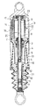
以下、この発明の実施の一形態を図について説明するが、図1は、この発明の車高調整装置の全体を示す断面図であり、図において、15は、車体に係止される外筒16内に配設されたシリンダ、11は、車輪に係止されて上記シリンダ15内を摺動するピストン3を具備するピストンロッドである。
【0025】
また、10は、ピストンロッド11内に設けられて、これとの間に上記ピストン3により区画された高圧室13a,13bのうち高圧室13bに通じる油路17を形成する円筒状のポンプシリンダ、22は、上記外筒16の底部16aとの間に高圧ガスおよび油を貯溜する高圧ガス貯溜室23を隔成するところの隔成板である。
【0026】
さらに、24は、隔成板22に形成されて、上記ピストン3によって隔成された上記高圧室13aと上記高圧ガス貯溜室23とに連通する連通孔である。
【0027】
9は、ポンプロッドで、これが上記隔成板22に一端が保持されるように上記ポンプシリンダ10内に挿通されて、途中には、上記高圧室13aに開口可能な制御オリフイス2を他端部には径方向に貫通する吐出ポート26aをそれぞれ持つもので、該他端部は閉塞されている。
【0028】
また、12は、上記ピストンロッド11内のポンプシリンダ10下部に形成されたポンプ室、1は、上記外筒16内に設けられたオイルリザーバで、これが上記隔成板22に形成された油孔25,上記ポンプロッド9内およびチェック弁としてのポンプチェック弁26を通じて上記ポンプ室12に連通する。
【0029】
さらに、4は、上記シリンダ15および外筒16の間に上記オイルリザーバ1および低圧ガス室27を隔成するダイヤフラムである。
【0030】
28は、上記隔成板22に設けられて、該隔成板22下部の上記オイルリザーバ1内のガスを上記高圧ガス貯溜室23へ抜くガス抜きチェック弁である。
【0031】
なお、高圧ガス貯溜室23にはガスと油との間を隔成するダイヤフラムは設けられていない。
【0032】
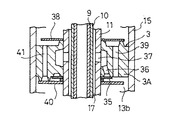
また、上記ピストン3には、図2に示すように、上記圧行程において上記ポンプ室12の油を上記高圧室12bへ導出するチェック弁35を設けてある。
【0033】
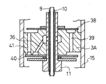
なお、必要に応じて、上記ピストン3に設けられるチェック弁35を、図3に示すように、上記ピストン3に設けられた圧側減衰力発生用の減衰力発生バルブ40と共用することもできる。
【0034】
また、29は、上記外筒16の下端開口をピストンロッド11外周に接するオイルシール30を介して塞ぐキャップ、31は、このキャップ29の内側面中央部に保持されて、上記シリンダ15の下端を密閉するベアリングで、このベアリング31の中心部および上記オイルシール30には上記ピストンロッド11が摺動自在にかつ油密的に支承されている。
【0035】
32は、上記外筒16の底部16a中心に貫通形成されたガス注入孔で、このガス注入孔32は、車体取付側部材33の溶接によって栓がなされており、34は、隔成板22を底部16aに支持する支持部材である。
【0036】
また、上記ピストン3は、図2に示すように構成され、シリンダ15内を摺動するピストン本体3Aには、高圧室13b側に設けられたチェック弁35により開閉される油路36が形成され、この油路36の他端がピストンロッド11に形成された油孔37を通して上記油路17に連通している。
【0037】
なお、38は、ピストン3に形成された油孔39を開閉する伸側減衰バルブ、40は、油孔41を開閉する圧側減衰バルブである。
【0038】
次に、動作について説明すると、まず、車両への積荷が多くなって車高が低下した場合には、ショックアブソーバが圧縮力を受けて全長が縮むことになり、このため、ピストンロッド11は、シリンダ15内に進入し、制御オリフィス2がポンプシリンダ10内に入り込んでしまう。
【0039】
なお、このとき、ポンプチェック弁26側の吐出ポート26aがポンプシリンダ10の下端から外へ出る状態とする。
【0040】
かかる状態にて、車両が走行し、ショックアブソーバが加振された場合には、その加振による伸行程では、オイルリザーバ1内の油が、油孔25,ポンプロッド9内油路,ポンプチェック弁26,吐出ポート26aをそれぞれ介してポンプ室12内に入り込む。
【0041】
一方、上記加振による圧行程では、そのポンプ室12内の油がポンプロッド9下端により押されて油路17,ピストン3に形成されたチェック弁35を介してシリンダ15内の高圧室13bへと流れ込む。
【0042】
こうして、高圧室13bに油が流れ込むと、その流れ込んだ体積分だけ、高圧室13a,連通孔24を介して高圧ガス貯溜室23が圧縮され、この高圧ガス貯溜室23内の圧力が高まる。
【0043】
このため、この圧力を受けてピストンロッド11の反発力が増大し、この反発力の増大によってピストン3がシリンダ15内にて押し上げられ、車高が上昇することとなる。
【0044】
なお、この高圧ガス貯溜室23内の圧力の増加は、ポンプシリンダ10におけるポンプロッド9の上昇によって、吐出ポート26aがポンプシリンダ10内に入り込むことにより、つまり、伸行程によってオイルリザーバ1からポンプ室12に油を汲み上げなくなるまで続くことになる。
【0045】
一方、車両の荷降ろしが行われるなどして、車高が上昇した場合には、ショックアブソーバが伸長する。
【0046】
このため、ピストンロッド11は、シリンダ15の外へ進出して全長が伸び、上記制御オリフィス2がポンプシリンダ10の外に出ることとなり、このため、その制御オリフィス2およびポンプロッド9の油路を通じて高圧室13aとオイルリザーバ1とが連通することとなり、その高圧室13a内の油がオイルリザーバ1内へ流入する。
【0047】
そして、その流入した油の体積分だけ、連通孔24を通じて高圧ガス貯溜室23内のガス室体積が膨張し、これにより、高圧室13a内の圧力が低下し、上記とは逆にピストンロッド11の反発力が低減し、この反発力の低減によって車高が低下することとなる。
【0048】
なお、この車高の低下は、制御オリフィス2がポンプシリンダ10内に入り込んで高圧室13aとオイルリザーバ1とが油圧的に分離されるまで続けられる。
【0049】
また、車高の上下動作中に、高圧ガス貯溜室23内のガスばね用のガスが油とともに連通孔24,高圧室13a,制御オリフィス2,ポンプロッド9内,油孔25を介してオイルリザーバ1内に入り込んでしまう場合がある。
【0050】
このような場合でも、このオイルリザーバ1内のガスは、その高圧室13a内の圧力よりもオイルリザーバ1内の圧力が高くなった場合などにガス抜きチェック弁28を介して高圧ガス貯溜室23のガス室へ直接導出させることができる。
【0051】
このため、ピストン3の摺動時において、高圧室13a内に滞留したガスの気泡のつぶれなどによる発生減衰力の不安定化を回避することが可能となる。
【0052】
なお、上記実施例においては、圧行程においてポンプ室12内の油を高圧室13bを導出するチェック弁35および油路36を、ピストン3のピストン本体3Aに独立して設けたものを示したが、図3に示すように、チェック弁35のみを圧側減衰力発生用の圧側減衰バルブ40と共用してもよい。
【0053】
このように、上記チェック弁35を圧側減衰バルブ40と共用することで、ピストン本体3の構成およびこれに取り付けられるバルブ設置構造やこれらの組立作業の容易化,迅速化が図れるという利点が得られる。
【0054】
なお、上記実施の形態においては、車高の低下時には制御オリフィス2をポンプシリンダ10内に入り込ませ、車高の上昇時には制御オリフィス2をポンプシリンダ10の外に出すようにするものを示したが、制御オリフィス2をポンプシリンダ10の外へ出る頻度の高いポンプロッド9の上部位置に設けることで、高圧室13aからの油の供給を受けてオイルリザーバ1の圧力が高くなる状態をより頻繁にすることができる。
【0055】
従って、上記オイルリザーバ1からの上記ガス抜きチェック弁28を通じての高圧ガス貯溜室23へのガス抜きをさらに確実かつ十分に行うことができる。
【0056】
また、上記実施の形態にあっては、車高低下時に吐出ポート26aがポンプシリンダ10の外に出て、高圧室13aの圧力を上昇させ、車高上昇時に吐出ポート26aがポンプシリンダ10の中に入り込むまで、高圧室13aの圧力を上昇させるようにした場合を示したが、上記吐出ポート26aを予め定めた中立位置、すなわち、ポンプシリンダ10内に入り込んで閉じられるポンプロッド9の所定部位に設けるようにしてもよい。
【0057】
この場合には、中立車高時に車両が微振幅加振によるポンピングを行われなくなるため、この中立車高時における車両の乗心地を改善することができる。
【0058】
また、上記制御オリフィス2を中立車高時にはオープンとなる位置に設けるとともに、上記吐出ポート26aを中立車高時にはクローズになる位置に設けることによって、オイルリザーバ1内のガス抜きの効率化とともに、中立車高時の車両の乗心地の改善を共に図ることができる。
【0059】
【発明の効果】
以上のように、請求項1の発明によれば、ピストンロッド内に設けられてこれとの間にピストンにより区画された高圧室に通じる油路を形成する円筒状のポンプシリンダと、外筒の底部との間に高圧ガスおよび油を貯溜する高圧ガス貯溜室を隔成する隔成板と、該隔成板に形成されて上記ピストンによって隔成された上記高圧室と上記ガス貯溜室とに連通する連通孔と、上記隔成板に一端が保持されるように上記ポンプシリンダ内に挿通されて途中には上記高圧室に開口する制御オリフイスを他端には径方向に貫通する吐出ポートをそれぞれ持ったポンプロッドと、上記ピストンロッド内のポンプシリンダ下部に形成されたポンプ室と、上記外筒内に設けられて上記ポンプロッド内およびチェック弁を通じて上記ポンプ室に連通するオイルリザーバと、シリンダおよび外筒間に上記オイルリザーバおよび低圧ガス室を隔成するダイヤフラムと、上記隔成板に設けられて該隔成板下部の上記オイルリザーバ内のガスを上記高圧ガス貯溜室へ抜くガス抜きチェック弁と、を備え、吐出ポートがポンプ室に開口される車高低下時に伸行程で上記オイルリザーバ内の油を上記ポンプ室に送り込み、次の圧行程でこのポンプ室の油を上記高圧室および上記高圧ガス貯溜室に送り込み、吐出ポートのポンプ室への連通が断たれその送り込みができなくなるまで上記ピストンロッドの反発力を高める一方で、制御オリフィスが上記高圧室に開口する車高上昇時に上記制御オリフィスを通じて上記高圧ガス貯溜室の油をオイルリザーバへ戻してピストンロッドの反発力を低減させるように構成したので、高圧ガスと油が貯溜される高圧ガス貯溜室にゴムのダイヤフラムを設ける必要がなくなり、従って、このダイヤフラムによるガスばねのヒステリシスの発生、あるいはダイヤフラムの耐久性劣化という問題発生を回避できることになり、これが結果的に車両の乗心地を改善することとなる。
【0060】
また、ガス抜きチェック弁によってオイルリザーバ内のガスを円滑に高圧ガス貯溜室へ送り出すことができるため、シリンダの高圧室にガスが残留するのを回避でき、従ってピストンの動作を安定化でき、結果的に減衰力動作の安定化およびこれによる車両の乗心地の向上を図ることができる。
【0061】
そして、請求項2の発明によれば、圧行程においてポンプ室の油を高圧室へ導出するチェック弁をピストンに設けるように構成したので、このチェック弁を通じて高圧室へ送り込んだ油の体積分だけ高圧ガス貯溜室のガスを圧縮してピストンロッドの反発力の増大および車高上昇を簡単に実現できるという効果が得られる。
【0062】
また、請求項3の発明によれば、ピストンに設けられるチェック弁を、ピストンに設けられた圧側減衰力発生用の減衰バルブと共用するように構成したので、チェック弁を別途用意することによる組立作業上およびコスト上の負担を顕著に軽減できるという効果が得られる。
【図面の簡単な説明】
【図1】この発明の実施の一形態による車高調整装置を示す断面図である。
【図2】図1におけるピストンの構造を詳細に示す拡大断面図である。
【図3】図1におけるチェック弁の他の実施形態を示す拡大断面図である。
【図4】従来の車高調整装置を示す縦断面図である。
【符号の説明】
1 オイルリザーバ
2 制御オリフィス
3 ピストン
4 ダイヤフラム
9 ポンプロッド
10 ポンプシリンダ
11 ピストンロッド
12 ポンプ室
13a,13b 高圧室
15 シリンダ
16 外筒
17 油路
22 隔成板
23 高圧ガス貯溜室
24 連通孔
25 油孔
26 ポンプチェック弁(チェック弁)
26a 吐出ポート
27 低圧ガス室
28 ガス抜きチェック弁
35 チェック弁
40 減衰力発生バルブ[0001]
BACKGROUND OF THE INVENTION
The present invention relates to a vehicle height adjusting device used for automobiles, motorcycles, industrial vehicles and the like.
[0002]
[Prior art]
As a conventional vehicle height adjusting device, for example, a self-pumping type shock absorber made by Bogen as shown in FIG. 4 is provided. To explain this, first, 15 is an outer cylinder that is locked to the vehicle body. 16 is a cylinder disposed in the cylinder 16.
[0003]
A piston rod 11 includes a piston 3 that is locked to a wheel and slides in the cylinder 15. A piston rod 10 is provided in the piston rod 11 and is partitioned by the piston 3 therebetween. This is a cylindrical pump cylinder that forms an oil passage 17 communicating with the high pressure chamber 13.
[0004]
Further, reference numeral 9 denotes a control orifice for lowering the vehicle height, one end of which is held at the bottom (the inner surface of the upper end) of the outer cylinder 16 and the other end is inserted into the pump cylinder 10 and opens to the high pressure chamber 13 in the middle. This is a pump rod with two.
[0005]
An oil reservoir 1 is provided in the outer cylinder 16 and communicates with the pump chamber 12 in the lower part of the pump cylinder 10 through the pump rod 9 and the inlet valve 6.
[0006]
7 is an outlet valve provided between the pump chamber 12 and the oil passage 17 below the pump cylinder 10, and 5 is a high-pressure chamber 18 and a gas chamber 5 in the outer cylinder 16 communicating with the high-pressure chamber 13. It is a diaphragm that separates
[0007]
Reference numeral 8 denotes a notch groove provided in a part of the outer periphery of the pump rod 9 over a certain length in the axial direction. When the upper portion of the notch groove protrudes above the pump cylinder 10, the high pressure chamber 13 and the pump chamber function.
[0008]
Next, the operation will be described. Considering the case where the load on the vehicle increases and the vehicle height decreases, the entire vehicle height adjusting device as a shock absorber is shrunk under the compression force, The control orifice 2 and the notch 8 are located in the pump cylinder 10.
[0009]
In this state, when the vehicle travels and an excitation force is applied to the shock absorber, the oil in the oil reservoir 1 is transferred to the communication pipe 19, the oil passage 20 in the pump rod 9, and the inlet during the extension stroke of the piston rod 11 at this time. It enters into the pump chamber 12 through the valves 6 respectively.
[0010]
On the other hand, in the subsequent pressure stroke, the oil in the pump chamber 12 is pushed by the pump rod 9 and flows into the high pressure chamber 13 through the outlet valve 7, the oil passage 17 between the pump cylinder 10 and the piston rod 11. .
[0011]
Then, the high volume chamber 18 separated by the diaphragm 4 is obtained by the volume of the oil flowing into the high pressure chamber 13 and through the small hole 21 provided in the bottom of the cylinder 15 and the oil passage 22 on the outer periphery of the cylinder 15. Flow into.
[0012]
For this reason, the gas chamber 5 is compressed by an amount corresponding to the volume, the high pressure chamber 18 becomes high pressure, the repulsive force of the piston rod 11 increases, and the vehicle height increases due to the increase of the repulsive force. Become.
[0013]
On the other hand, the increase in the pressure in the high pressure chamber 13 is caused by the notch 8 coming out of the pump cylinder 10 due to the rise in the vehicle height, the high pressure chamber 13 and the pump chamber 12 communicating, and the pump chamber 12 becoming high pressure. The inlet valve 6 is closed so as to press it, and this extension process is continued until no oil is pumped from the oil reservoir 1 to the pump chamber 12.
[0014]
Next, when the vehicle height rises by unloading from the vehicle or the like, the overall length of the shock absorber is extended. When the control orifice 2 comes to the outside of the pump cylinder 10, the high pressure chamber 13 and the oil reservoir 1 communicates with the control orifice 2.
[0015]
For this reason, the oil in the high pressure chamber 13 flows into the oil reservoir 1, and the volume of the gas chamber 5 expands by the volume of the oil discharged from the high pressure chamber 13 due to this inflow, thereby reducing the pressure in the high pressure chamber 13. Then, the repulsion of the piston rod 11 decreases, and the vehicle height decreases.
[0016]
This reduction in vehicle height continues until the control orifice 2 enters the pump cylinder 10 and the oil flow between the high pressure chamber 13 and the oil reservoir 1 is divided.
[0017]
[Problems to be solved by the invention]
Since the conventional vehicle height adjusting device is configured as described above, the diaphragm 4 that separates the high-pressure chamber 18 and the gas chamber 5 increases the hysteresis of the gas spring operation, thereby deteriorating the riding comfort of the vehicle. There was a problem to do.
[0018]
Further, since the gas compression ratio is large and the expansion and compression operations are frequent, there is a problem that the durability of the diaphragm 4 itself is remarkably lowered.
[0019]
Furthermore, once the gas in the oil reservoir 1 flows into a portion higher than the oil reservoir 1 in the high pressure chamber 13, it becomes difficult to remove the gas from the high pressure chamber 13, and the movement of the piston 3 in the cylinder 15 is not possible. There was a problem that the damping force waveform generated by this became unstable and the riding comfort of the vehicle deteriorated.
[0020]
The present invention has been made to solve the above-described problems, and by reducing the hysteresis of the gas spring, it is possible to improve the riding comfort of the vehicle, improve the durability of the gas spring, and improve the inside of the cylinder. It is an object of the present invention to provide a vehicle height adjusting device that can realize degassing well.
[0021]
[Means for Solving the Problems]
The vehicle height adjusting device according to the first aspect of the present invention includes a cylindrical pump cylinder provided in a piston rod and forming an oil passage leading to a high pressure chamber defined by the piston, and a bottom portion of the outer cylinder. A partition plate separating a high-pressure gas storage chamber for storing high-pressure gas and oil therebetween, and communicating with the high-pressure chamber formed on the partition plate and separated by the piston and the gas storage chamber A communicating orifice that is inserted into the pump cylinder so that one end is held by the partition plate, and a discharge port that penetrates in the radial direction at the other end and a control orifice that opens to the high pressure chamber in the middle. A pump rod formed at the bottom of the pump cylinder in the piston rod, and an oil reservoir provided in the outer cylinder and communicating with the pump chamber through the pump rod and the check valve. And a diaphragm that separates the oil reservoir and the low-pressure gas chamber between the cylinder and the outer cylinder, and a gas in the oil reservoir that is provided on the partition plate and is located below the partition plate. A degassing check valve that vents to the pump chamber, and when the vehicle height drops when the discharge port opens to the pump chamber, the oil in the oil reservoir is sent to the pump chamber during the extension stroke, and the oil in the pump chamber is transferred during the next pressure stroke. Is supplied to the high pressure chamber and the high pressure gas storage chamber, and the repulsive force of the piston rod is increased until the communication of the discharge port to the pump chamber is interrupted and the pumping cannot be performed, while the control orifice opens to the high pressure chamber. The oil in the high-pressure gas storage chamber is returned to the oil reservoir through the control orifice when the vehicle height rises, and the repulsive force of the piston rod is reduced. That.
[0022]
According to a second aspect of the present invention, there is provided a vehicle height adjusting device comprising a piston provided with a check valve that guides the oil in the pump chamber to the high pressure chamber in a pressure stroke.
[0023]
Furthermore, the vehicle height adjusting device according to the invention of claim 3 is configured such that the check valve provided in the piston is shared with the damping valve for generating the compression side damping force provided in the piston.
[0024]
DETAILED DESCRIPTION OF THE INVENTION
1 is a cross-sectional view showing the entire vehicle height adjusting device of the present invention. In the figure, reference numeral 15 denotes an outer cylinder that is locked to a vehicle body. A cylinder 11, 11 is a piston rod provided with a piston 3 that is locked to a wheel and slides inside the cylinder 15.
[0025]
A cylindrical pump cylinder 10 is provided in the piston rod 11 and forms an oil passage 17 leading to the high pressure chamber 13b among the high pressure chambers 13a and 13b partitioned by the piston 3 between them. Reference numeral 22 denotes a partition plate that separates a high-pressure gas storage chamber 23 that stores high-pressure gas and oil between the bottom portion 16 a of the outer cylinder 16.
[0026]
Further, 24 is a communication hole formed in the partition plate 22 and communicating with the high-pressure chamber 13 a and the high-pressure gas storage chamber 23 separated by the piston 3.
[0027]
9 is a pump rod, which is inserted into the pump cylinder 10 so that one end is held by the separating plate 22, and a control orifice 2 that can be opened to the high-pressure chamber 13a is inserted in the other end portion in the middle. Each has a discharge port 26a penetrating in the radial direction, and the other end is closed.
[0028]
Reference numeral 12 denotes a pump chamber formed in the lower part of the pump cylinder 10 in the piston rod 11, and 1 denotes an oil reservoir provided in the outer cylinder 16, which is an oil hole formed in the partition plate 22. 25. It communicates with the pump chamber 12 through the pump rod 9 and a pump check valve 26 as a check valve.
[0029]
Reference numeral 4 denotes a diaphragm that separates the oil reservoir 1 and the low-pressure gas chamber 27 between the cylinder 15 and the outer cylinder 16.
[0030]
Reference numeral 28 denotes a degassing check valve that is provided on the partition plate 22 and draws the gas in the oil reservoir 1 below the partition plate 22 into the high-pressure gas storage chamber 23.
[0031]
The high-pressure gas storage chamber 23 is not provided with a diaphragm that separates gas and oil.
[0032]
Further, as shown in FIG. 2, the piston 3 is provided with a check valve 35 for leading the oil in the pump chamber 12 to the high pressure chamber 12b in the pressure stroke.
[0033]
If necessary, the check valve 35 provided in the piston 3 can be shared with a damping force generation valve 40 for generating a compression side damping force provided in the piston 3 as shown in FIG.
[0034]
Reference numeral 29 denotes a cap that closes the lower end opening of the outer cylinder 16 via an oil seal 30 that is in contact with the outer periphery of the piston rod 11, and 31 is held at the center of the inner surface of the cap 29 so that the lower end of the cylinder 15 is covered. The piston rod 11 is slidably and oil-tightly supported on the center of the bearing 31 and the oil seal 30 by a hermetically sealed bearing.
[0035]
Reference numeral 32 denotes a gas injection hole formed through the center of the bottom portion 16a of the outer cylinder 16. The gas injection hole 32 is plugged by welding of the vehicle body attachment side member 33, and 34 denotes the separation plate 22. It is a support member supported by the bottom part 16a.
[0036]
The piston 3 is configured as shown in FIG. 2, and an oil passage 36 that is opened and closed by a check valve 35 provided on the high pressure chamber 13b side is formed in the piston main body 3A that slides in the cylinder 15. The other end of the oil passage 36 communicates with the oil passage 17 through an oil hole 37 formed in the piston rod 11.
[0037]
Reference numeral 38 denotes an expansion side damping valve that opens and closes an oil hole 39 formed in the piston 3, and reference numeral 40 denotes a compression side damping valve that opens and closes the oil hole 41.
[0038]
Next, the operation will be described. First, when the load on the vehicle increases and the vehicle height decreases, the shock absorber receives the compressive force and the entire length is shortened. The control orifice 2 enters the pump cylinder 10 by entering the cylinder 15.
[0039]
At this time, the discharge port 26a on the pump check valve 26 side is in a state of going out from the lower end of the pump cylinder 10.
[0040]
In such a state, when the vehicle travels and the shock absorber is vibrated, the oil in the oil reservoir 1 becomes oil hole 25, the oil passage in the pump rod 9, the pump check in the extension stroke by the vibration. It enters the pump chamber 12 through the valve 26 and the discharge port 26a.
[0041]
On the other hand, in the pressure stroke by the vibration, the oil in the pump chamber 12 is pushed by the lower end of the pump rod 9 to the high pressure chamber 13b in the cylinder 15 through the check valve 35 formed in the oil passage 17 and the piston 3. And flow into.
[0042]
Thus, when oil flows into the high-pressure chamber 13b, the high-pressure gas storage chamber 23 is compressed through the high-pressure chamber 13a and the communication hole 24 by the volume that has flowed in, and the pressure in the high-pressure gas storage chamber 23 increases.
[0043]
For this reason, the repulsive force of the piston rod 11 increases due to this pressure, and the piston 3 is pushed up in the cylinder 15 due to the increase of the repulsive force, and the vehicle height increases.
[0044]
The increase in the pressure in the high-pressure gas storage chamber 23 is caused by the pump rod 9 rising in the pump cylinder 10 and the discharge port 26a entering the pump cylinder 10, that is, from the oil reservoir 1 to the pump chamber by the extension stroke. It will continue until no oil is pumped to 12.
[0045]
On the other hand, when the vehicle height rises, such as when the vehicle is unloaded, the shock absorber extends.
[0046]
For this reason, the piston rod 11 advances to the outside of the cylinder 15 and the entire length is extended, and the control orifice 2 comes out of the pump cylinder 10, and therefore, through the oil passage of the control orifice 2 and the pump rod 9. The high pressure chamber 13a and the oil reservoir 1 are in communication with each other, and the oil in the high pressure chamber 13a flows into the oil reservoir 1.
[0047]
Then, the volume of the gas chamber in the high-pressure gas storage chamber 23 is expanded through the communication hole 24 by the volume of the oil that has flowed in, whereby the pressure in the high-pressure chamber 13a is reduced, and the piston rod 11 is contrary to the above. The repulsive force of the vehicle is reduced, and the vehicle height is lowered by the reduction of the repulsive force.
[0048]
This reduction in vehicle height continues until the control orifice 2 enters the pump cylinder 10 and the high pressure chamber 13a and the oil reservoir 1 are separated hydraulically.
[0049]
Further, during the vertical movement of the vehicle height, the gas for the gas spring in the high-pressure gas storage chamber 23 together with oil passes through the communication hole 24, the high-pressure chamber 13a, the control orifice 2, the pump rod 9, and the oil hole 25 through the oil reservoir. There is a case where it enters into 1.
[0050]
Even in such a case, the gas in the oil reservoir 1 is stored in the high-pressure gas storage chamber 23 via the degas check valve 28 when the pressure in the oil reservoir 1 becomes higher than the pressure in the high-pressure chamber 13a. Can be led directly to the gas chamber.
[0051]
For this reason, when the piston 3 is slid, it is possible to avoid the instability of the generated damping force due to the collapse of the bubbles of the gas retained in the high pressure chamber 13a.
[0052]
In the above embodiment, the check valve 35 and the oil passage 36 for leading the oil in the pump chamber 12 to the high pressure chamber 13b in the pressure stroke are provided independently in the piston body 3A of the piston 3. As shown in FIG. 3, only the check valve 35 may be shared with the compression side damping valve 40 for generating the compression side damping force.
[0053]
Thus, by using the check valve 35 in common with the pressure side damping valve 40, there is an advantage that the structure of the piston body 3, the valve installation structure attached to the piston body 3, and the assembly work thereof can be facilitated and speeded up. .
[0054]
In the above embodiment, the control orifice 2 is inserted into the pump cylinder 10 when the vehicle height is lowered, and the control orifice 2 is moved out of the pump cylinder 10 when the vehicle height is raised. By providing the control orifice 2 at the upper position of the pump rod 9 which frequently goes out of the pump cylinder 10, the state in which the pressure of the oil reservoir 1 is increased due to the supply of oil from the high pressure chamber 13a is more frequent. can do.
[0055]
Accordingly, it is possible to more reliably and sufficiently degas the high pressure gas storage chamber 23 from the oil reservoir 1 through the degas check valve 28.
[0056]
Further, in the above embodiment, the discharge port 26a goes out of the pump cylinder 10 when the vehicle height is lowered to increase the pressure in the high pressure chamber 13a, and the discharge port 26a is moved into the pump cylinder 10 when the vehicle height is raised. Although the case where the pressure in the high-pressure chamber 13a is increased until it enters, the discharge port 26a is set at a predetermined neutral position, that is, at a predetermined portion of the pump rod 9 that enters the pump cylinder 10 and is closed. You may make it provide.
[0057]
In this case, since the vehicle is not pumped by the fine amplitude excitation at the neutral vehicle height, the riding comfort of the vehicle at the neutral vehicle height can be improved.
[0058]
The control orifice 2 is provided at a position that is open when the vehicle is in a neutral position, and the discharge port 26a is provided at a position that is closed when the vehicle is in a neutral position. It is possible to improve the ride comfort of the vehicle at the time of vehicle height.
[0059]
【The invention's effect】
As described above, according to the first aspect of the present invention, the cylindrical pump cylinder which is provided in the piston rod and forms an oil passage leading to the high pressure chamber partitioned by the piston, and the outer cylinder A partition plate separating a high-pressure gas storage chamber for storing high-pressure gas and oil between the bottom portion, the high-pressure chamber formed on the partition plate and separated by the piston, and the gas storage chamber; A communication hole that communicates with the control orifice that opens into the high-pressure chamber in the middle of the pump cylinder so that one end is held by the partition plate, and a discharge port that penetrates in the radial direction at the other end. Each of the pump rods, a pump chamber formed in the lower part of the pump cylinder in the piston rod, and an oil reservoir provided in the outer cylinder and communicating with the pump chamber through the pump rod and a check valve. And a diaphragm that separates the oil reservoir and the low-pressure gas chamber between the cylinder and the outer cylinder, and a gas in the oil reservoir that is provided on the partition plate and is located below the partition plate. A degassing check valve that vents to the pump chamber, and when the vehicle height drops when the discharge port opens to the pump chamber, the oil in the oil reservoir is sent to the pump chamber during the extension stroke, and the oil in the pump chamber is transferred during the next pressure stroke. Is supplied to the high pressure chamber and the high pressure gas storage chamber, and the repulsive force of the piston rod is increased until the communication of the discharge port to the pump chamber is interrupted and the pumping cannot be performed, while the control orifice opens to the high pressure chamber. When the vehicle height rises, the oil in the high pressure gas storage chamber is returned to the oil reservoir through the control orifice to reduce the repulsive force of the piston rod. Therefore, it is no longer necessary to provide a rubber diaphragm in the high-pressure gas storage chamber in which high-pressure gas and oil are stored. Therefore, it is possible to avoid the occurrence of gas spring hysteresis due to this diaphragm or the deterioration of the durability of the diaphragm. As a result, the ride comfort of the vehicle is improved.
[0060]
In addition, the gas vent check valve can smoothly send the gas in the oil reservoir to the high-pressure gas storage chamber, so that gas can be prevented from remaining in the high-pressure chamber of the cylinder, and the piston operation can be stabilized. In particular, the damping force operation can be stabilized and the riding comfort of the vehicle can be improved.
[0061]
According to the invention of claim 2, since the piston is provided with the check valve for leading the oil in the pump chamber to the high pressure chamber in the pressure stroke, only the volume fraction of the oil fed into the high pressure chamber through this check valve is provided. An effect is obtained that the gas in the high-pressure gas storage chamber is compressed to easily increase the repulsive force of the piston rod and raise the vehicle height.
[0062]
According to the invention of claim 3, since the check valve provided on the piston is configured to be shared with the damping valve for generating the compression side damping force provided on the piston, assembly by separately preparing the check valve The effect that the burden on work and cost can be remarkably reduced is obtained.
[Brief description of the drawings]
FIG. 1 is a cross-sectional view showing a vehicle height adjusting device according to an embodiment of the present invention.
FIG. 2 is an enlarged cross-sectional view showing in detail the structure of the piston in FIG.
3 is an enlarged cross-sectional view showing another embodiment of the check valve in FIG. 1. FIG.
FIG. 4 is a longitudinal sectional view showing a conventional vehicle height adjusting device.
[Explanation of symbols]
DESCRIPTION OF SYMBOLS 1 Oil reservoir 2 Control orifice 3 Piston 4 Diaphragm 9 Pump rod 10 Pump cylinder 11 Piston rod 12 Pump chamber 13a, 13b High pressure chamber 15 Cylinder 16 Outer cylinder 17 Oil path 22 Separation plate 23 High pressure gas storage chamber 24 Communication hole 25 Oil hole 26 Pump check valve (check valve)
26a Discharge port 27 Low pressure gas chamber 28 Degassing check valve 35 Check valve 40 Damping force generating valve