JP3648564B2 - Multi-cavity powder molding press - Google Patents
Multi-cavity powder molding press Download PDFInfo
- Publication number
- JP3648564B2 JP3648564B2 JP2002296012A JP2002296012A JP3648564B2 JP 3648564 B2 JP3648564 B2 JP 3648564B2 JP 2002296012 A JP2002296012 A JP 2002296012A JP 2002296012 A JP2002296012 A JP 2002296012A JP 3648564 B2 JP3648564 B2 JP 3648564B2
- Authority
- JP
- Japan
- Prior art keywords
- powder
- hopper
- weighing
- hoppers
- molding
- Prior art date
- Legal status (The legal status is an assumption and is not a legal conclusion. Google has not performed a legal analysis and makes no representation as to the accuracy of the status listed.)
- Expired - Lifetime
Links
Images
Landscapes
- Powder Metallurgy (AREA)
Description
【0001】
【発明の属する技術分野】
本発明は、粉末冶金における粉末成形プレスに関し、特に成形粉末を両押成形(フローティングダイ法、ウィズドロアル法の両方法を含む)することによって1個の金型で複数個の圧粉成形品を同時に得るための多数個取り粉末成形プレスに関する。
【0002】
【従来の技術】
多数個取り粉末成形プレスにおけるツールセットについての基本的な構造については、既に広く知られるところである。
また、成形に際して重量秤量・重量充填方式で行わせるものとしては、同様に知られるところである(例えば、特許文献1参照。)。
【0003】
【特許文献1】
特開2002−1592号公報(第4頁左欄の第1行〜第20行及び図3)
【0004】
従来周知の構造の多数個取り粉末成形プレスにおいて成形粉末のダイへの供給方法は体積充填方式によるものであって、構造が簡単であること、生産性の向上を図る点で好ましいことなどから専らこの方式が採用されていたのである。
【0005】
体積充填方式としては、設定された充填深さに粉末の自重落下によって行う「落し込み充填」と、抜出し状態でフィーダをダイホルダ上に移動させた後、ダイ上昇又は下パンチ下降によって行う「吸込み充填」とがあるが、何れも充填された粉末の質量にバラツキが生じて、圧粉体の高さ寸法、密度バラツキ精度が低下する問題がある。
【0006】
ところで、従来の体積充填方式による多数個取り粉末成形プレスに対して、特許文献1に示される如き重量秤量・重量充填方式のものを採用することが一応考えられるが、この場合、多数個のダイに対して、正確な重量秤量を実施した粉末を同時の一斉にしかも生産性良く確実に充填させ得ることは、従来の技術手段では容易には行えないものであって、この点がネックとなって現状ではこうした重量秤量・重量充填方式の多数個取り粉末成形プレスは今以て提供されるに至っていないと言うのが実状である。
【0007】
【発明が解決しようとする課題】
このような問題点を解決するべく本発明は成されたものであって、従って、本発明の目的は、高さ寸法、密度バラツキ精度の向上を図るとともに、生産性の増強を果たし得る自動粉末成形が可能な多数個取り粉末成形プレスを提供することにある。
【0008】
【課題を解決するための手段】
しかして本出願人は、上記課題を解決するためとして、請求項1の発明は、成形粉末を加圧成形して複数個の圧粉成形品を同時に得るための多数個取り粉末成形プレスであって、所定の配列パターンで配設される複数個のダイ7、各ダイ7を一体に保持するダイホルダ8、各ダイ7に対応して上下動可能に設けられる複数個の上パンチ9及び複数個の下パンチ10からなる金型を備えるツールセット1と、前記各ダイ7と同じ配列パターンで設けられる複数個の給粉ホッパ11を備え、ダイホルダ8の上面に沿う合心位置に側方の待機位置から一体に横移動させて、各給粉ホッパ11内の所定重量の成形粉末を各ダイ7に充填させる給粉フィーダ装置2と、重量検出器18を有し前記待機位置にある複数個の給粉ホッパ11の上方に同じ配列パターンで設けられる複数個の秤量ホッパ12、その周りに設けられる同数の第1段中継ホッパ13、両ホッパ12、13間に亘って設けられる供給量が調節可能な複数個の給粉シュート14を備え、第1段中継ホッパ13及び給粉シュート14を経て各秤量ホッパ12内に所定重量の成形粉末をそれぞれ収容させる秤量装置3と、秤量ホッパ12と同数の分配底口23を有し秤量ホッパ12の上方に設けられる粉末ホッパ15を備え、各分配底口23を各第1段中継ホッパ13にそれぞれ連絡して粉末ホッパ15内の成形粉末を各第1段中継ホッパ13に分配供給するホッパ装置4と、複数個の秤量ホッパ12と給粉ホッパ11の間に同じ配列パターンで一体に上下移動可能に設けられる複数個の第2段中継ホッパ16を備え、各秤量ホッパ12内の所定重量の成形粉末を受渡しにより各給粉ホッパ11に供給するサブホッパ装置5とを含んでいて、成形粉末がホッパ装置4から秤量装置3、サブホッパ装置5、給粉フィーダ装置2を順に経ることで実行される多数個同時重量秤量・重量充填が成された後において粉末成形が行われるようになっていることを特徴とする多数個取り粉末成形プレスを提供するものである。
【0009】
上記粉末成形プレスにおいて、予め数回分の加圧成形に見合った量の成形粉末がホッパ装置4の粉末ホッパ15内に送入されて底部に隙間なく均整に充填されているものとして、各分配底口23により等分配され放出された成形粉末を、秤量装置3の各第1段中継ホッパ13内に送らせ、この各中継ホッパ13内に適宜の量の成形粉末を一旦貯留させる。
【0010】
各秤量ホッパ12に溜まっている成形粉末を、各給粉シュート14内を経て供給量を調節しながら各秤量ホッパ12に送り込ませる。その際、各秤量ホッパ12側では重量検出器18の秤量作動が個々に行われるため、金型の各ダイ7での加圧成形分に見合った正確な重量の成形粉末を貯留することができ、一方、各給粉シュート14での給送は停止する。
【0011】
こうして、各秤量ホッパ12における重量秤量の下での粉末貯留が終わると、次に、各底口を開かせて、各秤量ホッパ12内の貯留粉末をその直下位置に配設しているサブホッパ装置5の各第2段中継ホッパ16内に送り込ませる。続いて、サブホッパ装置5を給粉フィーダ装置2の直上位置まで降下動させ、各第2段中継ホッパ16が各給粉ホッパ11の直真上位置に至ったところで、各底口を開かせて、各第2段中継ホッパ16内の貯留粉末を各給粉ホッパ11内にそれぞれ送り込ませる。
【0012】
各給粉ホッパ11への給粉フィーダ装置2からの粉末受渡しが成された時点で、次に、それらの給粉ホッパ11を前記ダイホルダ8の上面に沿う合心位置に側方の待機位置から一体に横移動させて、各給粉ホッパ11の底口が各ダイ7に対して合心位置に揃ったところで、それらの底口を開かせて給粉ホッパ11内の所定重量の成形粉末を対応する各ダイ7に充填させるようにする。かくして、一連の動作に基づく多数個同時重量秤量及び重量充填が確実かつ円滑に行われるものである。
【0013】
このように、本発明の粉末成形プレスによれば、複数個のダイ7におけると同様の所定の配列パターンで配設してなる複数個の給粉ホッパ11、秤量ホッパ12及び第2段中継ホッパ16を備えた構成としたこと、各秤量ホッパ12での確実な重量秤量を一斉に行わせ得る構成としたこととによって、「重量充填」方式に基づく多数個取り粉末成形プレスを容易に提供することが可能となったものである。
【0014】
また、上記課題を解決するためとして、請求項2の発明は、上記粉末成形プレスにおける秤量装置3の複数個の給粉シュート14が、該シュート14を給粉方向に振動させるリニアフィーダ20と、このリニアフィーダ20を少なくとも高速・中速・低速の3段に振動させる振動速度調節手段21とを備える構成とした多数個取り粉末成形プレスを提供するものである。
【0015】
上記粉末成形プレスにおいて、複数個の給粉シュート14での給粉の際に、リニアフィーダ20の振動速度を高速・中速・低速の3段に速度調節可能とすることにより、例えば、初めは高速振動で短時間に多量の粉末を給送し、中速・低速と順次振動速度を下げて、最終段階には給送量の微調整を行わせるなどの給送量コントロールが簡単かつ精確にできることから、重量秤量を精度よく、しかもスピーディに行える多数個取り粉末成形プレスを提供できる。
【0016】
【発明の実施の形態】
以下、本発明に係る多数個取り粉末成形プレスの実施形態について、各図面を参照しながら逐次説明する。
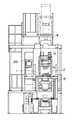
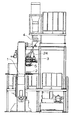
図1は、本発明の粉末成形プレスにおける第1の実施形態の外観示正面図を示し、また図2は、同じく外観示右側面図を示す。両図に図示の粉末成形プレスは、ツールセット1と、給粉フィーダ装置2と、秤量装置3と、ホッパ装置4と、サブホッパ装置5とを要素機構として備え、更に、ワーク搬出装置6を付帯機構として備える。
以上の各装置は、1基の多数個取り粉末成形プレスとしてシステム化されていて、左側中程にある操作ボックス25により全体の動作制御を集中管理できるようになっている。なお、この粉末成形プレスは、例えば同形の7個の円柱状圧粉成形品を同時に製造し得るように構成されている。
【0017】
○ツールセット1の構成:
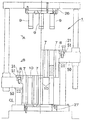
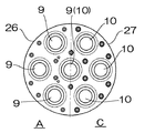
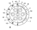
図3は、ツールセット1の一部断面示する正面図、図4は、図3の矢示線A、Cから見た上・下パンチ9、10の平面図、図5は、図3の矢示線Bから見たダイホルダ8部の断面図である。ツールセット1は、従来からある「ウィズドロアル法」による両押成形の多数個取りツールセットと基本的な構成は同じであって、所定の配列パターンで配設される7個のダイ7、各ダイ7を一体に保持するダイホルダ8、このダイホルダ8を取り巻いて支持するダイプレート50、各ダイ7に対応して上下動可能に設けられる7個の上パンチ9及び7個の下パンチ10を要素部材とする金型を備える。この場合、各ダイ7の配列パターンとしては、例えばダイホルダ8の中心に1点と、その周りの一つの仮想円周上の6等分周位置の6点との7位置を持つパターンに設定され、これに対応して7個の上パンチ9及び7個の下パンチ10が上パンチホルダ26及び下パンチホルダ27に取り付けられ、一方、ダイホルダ8は、加圧成形時に図3の中心線より右半部の最上位置と左半部の最下位置との間を下降動するようになっている。
【0018】
○給粉フィーダ装置2の構成:
図6は、給粉フィーダ装置2の一部省略示・機能示する平面図、図7は、同じく一部省略示・機能示する正面図である。給粉フィーダ装置2は、7個の給粉ホッパ11と、それらホッパ11を一体に横移動させるアクチュエータとしてのエアシリンダ28と、各ホッパ11に共通させて各底口を一斉に開閉口可能に設けた1枚のシャッタ17と、該シャッタ17を開閉口のために横摺動させるアクチュエータとしてのエアシリンダ29とを備える。
【0019】
ダイホルダ8を支持するダイプレート50に対して一対の水平レール31がフィーダテーブル51とセットで一体的に取付けられており、さらに、この一対の水平レール31に案内されて張り板30が水平移動可能に設けられていて、この張り板30に7個の給粉ホッパ11が各底口を等水平レベルの下向きに開口させて取り付けられている。この取付け状態では、前記各ダイ7と略同一の円形状を成している各底口が各ダイ7の配列パターンと同じパターン配列になっている。一方、上記張り板30と水平レール31の間にエアシリンダ28を亘らせて取り付けていて、このエアシリンダ28のロッド伸縮作動に伴って張り板30を水平移動させて、7個の給粉ホッパ11をダイホルダ8の直近側方の図2に示される待機位置からダイホルダ8の上面に沿う合心位置に、即ち、7個の各ダイ7と7個の各底口とが合心する位置に水平往復移動できるようになっている。
【0020】
一方、7個の給粉ホッパ11の直下部には、前記シャッタ17と、前記エアシリンダ29とが設けられている。シャッタ17は、図6に示すように7個の給粉ホッパ11の底口と略同一の円形状に形成した7個の孔32をそれら底口と同じ配列パターンの位置に穿孔させていて、エアシリンダ29のロッド伸縮作動に伴ってシャッタ17を水平移動させて、7個の孔32を各底口に全て合致させる一斉開口状態と図6に示す一斉閉口状態とに切り替え作動し得るようになっており、当然のことながら、この一斉開口状態は7個の給粉ホッパ11をダイホルダ8の上面に沿う合心位置にさせた充填動作の際に同期して行わせ、一斉閉口状態は充填操作以外の時期において行わせるものであるのは言うまでもない。なお、図6、7において33は、張り板30に取付けたガイド筒であり、また、34は、ガイド筒33に挿通してシャッタ17に取付けたガイド棒である。
【0021】
○秤量装置3の構成:
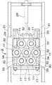
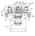
図8は、秤量装置3及びサブホッパ装置5の平面図を、図9は、同じく正面図を、図10は、秤量装置3の1単位構造体の正面図をそれぞれ示す。図示の秤量装置3は、7個の秤量ホッパ12と、7個の第1段中継ホッパ13と、7個の給粉シュート14と、各秤量ホッパ12に設けられるロードセルで実現される重量検出器18と、同じく各秤量ホッパ12に設けられるシャッタ19と、7個の給粉シュート14に設けられる加振動機構としてのリニアフィーダ20と、各リニアフィーダ20に付設される振動速度調節手段21とを備える。
【0022】
各秤量ホッパ12、各第1段中継ホッパ13、各給粉シュート14、各ロードセル18、各リニアフィーダ20及び各振動速度調節手段21の要素部材は、ベース35上に所定の配置でそれぞれ取付けられる。このベース35は、前記待機位置の給粉フィーダ装置2の真上方位置において架台36及びブラケット37を介して成形プレス本体枠に水平固定されている。
【0023】
7個の秤量ホッパ12は、各底口を等水平レベルの下向きに開口させてベース35の中央部に各ロードセル18を介して上下方向にレベル移動可能にそれぞれ取り付けられている。この取付け状態では、円形状を成している各底口が前記配列パターンと同じパターン配列であって、給粉フィーダ装置2の7個の給粉ホッパ11に対して真上方位置でそれぞれ合心した配置態様をとっている。それらの秤量ホッパ12は図10に示すように、楔形のシャッタ19が底口に開閉可能に介設されていて、アクチュエータとしてのエアシリンダ38によってシャッタ19を上下動させ底口を開閉するようになっている。
【0024】
7個の第1段中継ホッパ13は、対応する各秤量ホッパ12の周りに配置して各底口が秤量ホッパ12の頂部側入口に比して若干高レベル位置となるように高さを決めてベース35にそれぞれ固定させる。この場合、例えば図8に示すように、中心部の1個の秤量ホッパ12に対応する第1段中継ホッパ13はその手前側に配置し、左側の3個の各秤量ホッパ12に対応する3個の第1段中継ホッパ13はその左側に配置し、右側の3個の各秤量ホッパ12に対応する3個の第1段中継ホッパ13はその左側に配置することにより、コンパクトに纏まった取付けができる。
【0025】
一方、7個の給粉シュート14は、角ダクト状に形成した筒体がそれぞれ用いられていて、対関係にある第1段中継ホッパ13の底口と秤量ホッパ12の頂部側入口との間に亘らせて、図示しないが緩衝材などを介して微振動が可能に水平状に配設されている。この各給粉シュート14の下部には、リニアフィーダ20と振動速度調節手段21とを一体させて形成してなる加振動機構が取付けられていて、リニアフィーダ20を駆動し振動速度調節することにより、各給粉シュート14を長手側の給粉方向に振動させて給粉シュート14に送り込ませる粉末の供給量を増減調節することができるようになっている。なお、図10中の39は、給粉シュート14の中間部に配設した開口量調整用の調整ゲートである。
【0026】
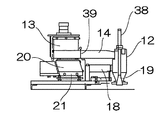
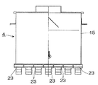
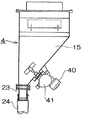
○ホッパ装置4の構成:
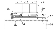
図11は、ホッパ装置4の正面図を、図12は、同じく縦断右側面図をそれぞれ示す。ホッパ装置4は1個の粉末ホッパ15を備えていて、秤量装置3の上方位置において成形プレス本体枠に取付けられる。この粉末ホッパ15は、底口部が秤量ホッパ12と同数(本実施態様では7個)で等形状の分配出口23を横一列に並べて開口してなる複出口形ホッパに形成されているとともに、本体内の適当な個所にはエアノッカ40とレベルスイッチ41とが取付けられている。エアノッカ40はホッパ15内の成形粉末が偏ったまま滞留することのないように、空気力を利用して各分配出口23上方に隙間なく均一にかつ安定した状態で成形粉末を貯留させるためのものであり、一方、レベルスイッチ41はホッパ15内の成形粉末の貯留量を一定に保持させるための検出器として設けられたものである。このように形成してなる粉末ホッパ15は、可とう性を有する例えばゴムホースからなる連絡管24を各分配出口23に接続して、この各ホース24端口を下方位置に存する各秤量ホッパ12の頂部入口にそれぞれ連結しており、このようにすることにより、粉末ホッパ15内の成形粉末を各秤量ホッパ12に均等に分配供給できるようになっている。
【0027】
○サブホッパ装置5の構成:
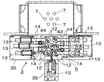
図13には、サブホッパ装置5の一部省略示底面図が表示される。図8、9及び図13を併せ参照して、サブホッパ装置5は、7個の第2段中継ホッパ16と、それらホッパ16を一体に上下移動させるアクチュエータとしてのエアシリンダ43と、上下移動の際の案内機構としてのガイド筒44及びガイド棒45からなるガイド部材と、各ホッパ16に共通させて各底口を一斉に開閉口可能に設けた1枚のシャッタ22と、該シャッタ22を開閉口のために横摺動させるアクチュエータとしてのエアシリンダ47とを備え、秤量装置3に関連してその直下部に設けて、装置全体としてエアシリンダ43と前記ガイド部材とによって前記ベース35に対し上下移動可能に取付けている。
【0028】
水平配置したホッパ取付板42はエアシリンダ43と前記ガイド部材とを介して前記ベース35に対し上下移動可能に取付けられ、このホッパ取付板42に7個の第2段中継ホッパ16が各底口を等水平レベルの下向きに開口させて固定されている。この取付け状態では、7個の第2段中継ホッパ16の各頂部ホッパ口が各秤量ホッパ12の底口に対してその配列パターンと同じパターン配列で合心し、一方、各底口が下方の各給粉ホッパ11に対してその配列パターンと同じパターン配列で合心するように位置付けられている。このように取付けられてなる7個の第2段中継ホッパ16は、エアシリンダ43のロッド伸縮作動に伴って、7個の各秤量ホッパ12と7個の各給粉ホッパ11との間で上下往復移動できるようになっている。
【0029】
一方、7個の第2段中継ホッパ16の各底口の直下部には、前記シャッタ22と、前記エアシリンダ47とが設けられている。シャッタ22は、図13に示すように7個の第2段中継ホッパ16の底口と略同一の円形状に形成した7個の孔46をそれら底口と同じ配列パターンの位置に穿孔させていて、前記ホッパ取付板42とシャッタ22とに亘って取付けたエアシリンダ47のロッド伸縮作動に伴ってシャッタ22を水平移動させて、7個の孔46を各底口に全て合致させる一斉開口状態と図13に示す一斉閉口状態とに切り替え作動し得るようになっている。なお、図13において48は、ホッパ取付板42に取付けたガイド筒であり、また、49は、ガイド筒48に挿通してシャッタ22に取付けたガイド棒である。
【0030】
○粉末成形プレスの動作:
予め所要回数分の加圧成形に見合った量の成形粉末がホッパ装置4の粉末ホッパ15内に送入されて底部に隙間なく均整に充填されているものとして、各分配底口23により等分配され放出された成形粉末を、秤量装置3の各第1段中継ホッパ13内に送らせ、この各中継ホッパ13内に適宜の量の成形粉末を一旦貯留させる。
【0031】
各中継ホッパ13に溜まっている成形粉末を、各給粉シュート14内を経て供給量を調節しながら各秤量ホッパ12に送り込ませる。その際、各給粉シュート14側では、リニアフィーダ20の振動速度を高速・中速・低速の3段に速度調節可能とすることにより、例えば、初めは高速振動で短時間に多量の粉末を給送し、中速・低速と順次振動速度を下げて、最終段階には給送量の微調整を行わせるなどの給送量コントロールが行われ、一方、各秤量ホッパ12側では重量検出器18による秤量作動が個々に行われ、これらによって、金型の各ダイ7での加圧成形分に見合った正確な重量の成形粉末を各秤量ホッパ12に貯留することができ、一方、各給粉シュート14での給送は停止する。
【0032】
こうして、各秤量ホッパ12における重量秤量の下での粉末貯留が終わると、次に、各底口を開かせて、各秤量ホッパ12内の貯留粉末をその直下位置に配設しているサブホッパ装置5の各第2段中継ホッパ16内に送り込ませる。続いて、サブホッパ装置5を給粉フィーダ装置2の直上位置まで降下動させ、各第2段中継ホッパ16が各給粉ホッパ11の直真上位置に至ったところで、各底口を開かせて、各第2段中継ホッパ16内の貯留粉末を各給粉ホッパ11内にそれぞれ送り込ませる。
【0033】
給粉フィーダ装置2の各給粉ホッパ11への粉末受渡しが成された時点で、次に、それらの給粉ホッパ11を前記ダイホルダ8の上面に沿う合心位置に側方の待機位置から一体に横移動させて、各給粉ホッパ11の底口が各ダイ7に対して合心位置に揃ったところで、それらの底口を開かせて給粉ホッパ11内の所定重量の成形粉末を対応する各ダイ7に充填させるようにする。かくして、一連の動作に基づく多数個同時重量秤量及び重量充填が確実かつ円滑に繰り返し行われるものである。
【0034】
【発明の効果】
本発明の多数個取り粉末成形プレスによれば、複数個のダイ7におけると同様の所定の配列パターンで配設してなる複数個の給粉ホッパ、秤量ホッパ及び第2段中継ホッパを備えた構成としたこと、各秤量ホッパでの確実な重量秤量を一斉に行わせ得る構成としたこととによって、「重量充填」方式に基づく多数個取り粉末成形プレスを容易に提供することが可能である。
【0035】
このように「重量充填」方式に基づく多数個取りが行えることにより、圧粉体の高さ寸法のバラツキを最小限に抑え得ることで、後工程(研磨など)の時間を短縮もしくは削減できて、生産性向上に寄与するところ多大である。また、圧粉体の密度バラツキを最小限に抑え得ることにより、製品としての性能向上が図れる利点がある。
【0036】
また、本発明は、秤量装置3の複数個の給粉シュートが、該シュートを給粉方向に振動させるリニアフィーダと、このリニアフィーダを少なくとも高速・中速・低速の3段に振動させる振動速度調節手段とを備える構成としたことにより、給送量コントロールが簡単かつ精確にできて重量秤量を精度よく、しかもスピーディに行える多数個取り粉末成形プレスを提供できる利点がある。
【図面の簡単な説明】
【図1】本発明の粉末成形プレスにおける第1の実施形態の外観示正面図。
【図2】本発明の粉末成形プレスにおける第1の実施形態の外観示右側面図。
【図3】ツールセット1の一部断面示する正面図。
【図4】図3の矢示線A,Cから見た上・下パンチ9,10の平面図。
【図5】図3の矢示線Bから見たダイホルダ8部の断面図。
【図6】給粉フィーダ装置2の一部省略示・機能示する平面図。
【図7】給粉フィーダ装置2の一部省略示・機能示する正面図。
【図8】秤量装置3及びサブホッパ装置5の平面図。
【図9】秤量装置3及びサブホッパ装置5の正面図。
【図10】秤量装置3の1単位構造体の正面図。
【図11】ホッパ装置4の正面図。
【図12】ホッパ装置4の縦断右側面図。
【図13】サブホッパ装置5の一部省略示底面図。
【符号の説明】
1…ツールセット 2…給粉フィーダ装置 3…秤量装置
4…ホッパ装置 5…サブホッパ装置 6…ワーク搬出装置
7…ダイ 8…ダイホルダ 9…上パンチ
10…下パンチ 11…給粉ホッパ 12…秤量ホッパ
13…第1段中継ホッパ 14…給粉シュート 15…粉末ホッパ
16…第2段中継ホッパ 17…シャッタ 18…重量検出器
19…シャッタ 20…リニアフィーダ 21…振動速度調節手段
22…シャッタ 23…分配底口 24…連絡管[0001]
BACKGROUND OF THE INVENTION
The present invention relates to a powder molding press in powder metallurgy, and in particular, a plurality of compacted molded products can be simultaneously formed with a single mold by performing both-press molding of a molded powder (including both floating die method and withdrawal method). The present invention relates to a multi-cavity powder molding press to obtain.
[0002]
[Prior art]
The basic structure of a tool set in a multi-piece powder molding press is already widely known.
In addition, it is known in the same way that molding is performed by a gravimetric weighing / weight filling method (see, for example, Patent Document 1).
[0003]
[Patent Document 1]
JP 2002-1592 A (the first line to the 20th line in the left column of
[0004]
In conventional multi-cavity powder molding presses with a well-known structure, the method of supplying the molding powder to the die is based on the volume filling method, which is preferred because it is simple in structure and preferable in terms of improving productivity. This method was adopted.
[0005]
As the volume filling method, “drop filling” is performed by dropping the powder by its own weight to a set filling depth, and “suction filling” is performed by moving the feeder onto the die holder in the withdrawn state and then raising the die or lowering the lower punch. However, there is a problem in that the mass of the filled powder varies, and the height dimension and density variation accuracy of the green compact decrease.
[0006]
By the way, it is conceivable to adopt a gravimetric weighing / weight filling method as shown in Patent Document 1 for a conventional multi-cavity powder molding press, but in this case, a large number of dies are used. On the other hand, it is impossible to easily and reliably fill powders that have been accurately weighed at the same time with good productivity, and this is a bottleneck. Under the present circumstances, it is actually said that such a multi-powder powder forming press of the gravimetric weighing / weight filling method has not yet been provided.
[0007]
[Problems to be solved by the invention]
The present invention has been made to solve such problems. Accordingly, the object of the present invention is to improve the height dimension and the density variation accuracy, and to improve the productivity. An object of the present invention is to provide a multi-cavity powder molding press that can be molded.
[0008]
[Means for Solving the Problems]
Therefore, in order to solve the above-mentioned problems, the applicant of the present invention is a multi-piece powder molding press for press-molding a molded powder to obtain a plurality of compacted products at the same time. A plurality of
[0009]
In the above powder molding press, it is assumed that an amount of molding powder commensurate with several times of pressure molding is fed into the
[0010]
The molding powder accumulated in each weighing
[0011]
Thus, when the powder storage under the weight weighing in each weighing
[0012]
When the powder delivery from the
[0013]
Thus, according to the powder molding press of the present invention, a plurality of
[0014]
In order to solve the above-mentioned problem, the invention of
[0015]
In the above powder molding press, when powdering with a plurality of
[0016]
DETAILED DESCRIPTION OF THE INVENTION
Hereinafter, embodiments of a multi-cavity powder molding press according to the present invention will be sequentially described with reference to the drawings.
FIG. 1 is a front view showing the appearance of the first embodiment of the powder molding press of the present invention, and FIG. 2 is a right side view showing the same appearance. The powder forming press shown in both figures includes a tool set 1, a powder
Each of the above devices is systemized as a single multi-piece powder molding press, and the entire operation control can be centrally managed by the
[0017]
○ Configuration of tool set 1 :
3 is a front view showing a partial cross section of the tool set 1, FIG. 4 is a plan view of the upper and
[0018]
○ Configuration of the powder feeder apparatus 2 :
FIG. 6 is a plan view showing a part of the
[0019]
A pair of
[0020]
On the other hand, the
[0021]
○ Configuration of weighing device 3 :
8 is a plan view of the weighing
[0022]
Element members of each weighing
[0023]
The seven weighing
[0024]
The seven first-
[0025]
On the other hand, the seven
[0026]
○ Configuration of the hopper device 4 :
FIG. 11 is a front view of the
[0027]
○ Configuration of sub-hopper device 5 :
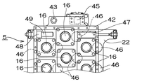
In FIG. 13, a partially omitted bottom view of the
[0028]
The horizontally disposed
[0029]
On the other hand, the
[0030]
○ Operation of powder molding press :
Assuming that the amount of molding powder corresponding to the required number of press moldings is fed into the
[0031]
The molding powder accumulated in each
[0032]
Thus, when the powder storage under the weight weighing in each weighing
[0033]
When the powder delivery to each of the
[0034]
【The invention's effect】
The multi-cavity powder molding press of the present invention includes a plurality of powder feeding hoppers, weighing hoppers, and second-stage relay hoppers arranged in a predetermined arrangement pattern similar to that in the plurality of dies 7. It is possible to easily provide a multi-piece powder molding press based on the “weight filling” method by having a configuration and a configuration in which reliable weight weighing can be performed simultaneously in each weighing hopper. .
[0035]
In this way, by taking a large number of pieces based on the “weight filling” method, it is possible to minimize variations in the height dimension of the green compact, thereby shortening or reducing the time for subsequent processes (such as polishing). It is a great place to contribute to productivity improvement. In addition, since the density variation of the green compact can be minimized, there is an advantage that the performance as a product can be improved.
[0036]
Further, the present invention provides a linear feeder that vibrates the chute in the powder feeding direction, and a vibration speed that vibrates the linear feeder in at least three stages of high speed, medium speed, and low speed. With the configuration including the adjusting means, there is an advantage that it is possible to provide a multi-piece powder molding press capable of easily and accurately controlling the feeding amount, accurately measuring the weight, and speedily.
[Brief description of the drawings]
FIG. 1 is a front view showing an external appearance of a first embodiment of a powder molding press according to the present invention.
FIG. 2 is a right side view showing the external appearance of the first embodiment in the powder molding press of the present invention.
FIG. 3 is a front view showing a partial cross section of the tool set 1;
4 is a plan view of the upper and
5 is a cross-sectional view of a portion of the
6 is a plan view showing a part of the
FIG. 7 is a front view showing a part of the
8 is a plan view of the weighing
9 is a front view of the weighing
10 is a front view of one unit structure of the weighing
11 is a front view of the
12 is a vertical right side view of the
13 is a partially omitted bottom view of the
[Explanation of symbols]
DESCRIPTION OF SYMBOLS 1 ... Tool set 2 ... Feeding
Claims (2)
所定の配列パターンで配設される複数個のダイ(7)、各ダイ(7)を一体に保持するダイホルダ(8)、各ダイ(7)に対応して上下動可能に設けられる複数個の上パンチ(9)及び複数個の下パンチ(10)からなる金型を備えるツールセット(1)と、
前記各ダイ(7)と同じ配列パターンで設けられる複数個の給粉ホッパ(11)を備え、ダイホルダ(8)の上面に沿う合心位置に側方の待機位置から一体に横移動させて、各給粉ホッパ(11)内の所定重量の成形粉末を各ダイ(7)に充填させる給粉フィーダ装置(2)と、
重量検出器(18)を有し前記待機位置にある複数個の給粉ホッパ(11)の上方に同じ配列パターンで設けられる複数個の秤量ホッパ(12)、その周りに設けられる同数の第1段中継ホッパ(13)、両ホッパ(12)、(13)間に亘って設けられる供給量が調節可能な複数個の給粉シュート(14)を備え、第1段中継ホッパ(13)及び給粉シュート(14)を経て各秤量ホッパ(12)内に所定重量の成形粉末をそれぞれ収容させる秤量装置(3)と、
秤量ホッパ(12)と同数の分配底口(23)を有し秤量ホッパ(12)の上方に設けられる粉末ホッパ(15)を備え、各分配底口(23)を第1段中継ホッパ(13)に連絡して粉末ホッパ(15)内の成形粉末を各第1段中継ホッパ(13)に分配供給するホッパ装置(4)と、
複数個の秤量ホッパ(12)と給粉ホッパ(11)の間に同じ配列パターンで一体に上下移動可能に設けられる複数個の第2段中継ホッパ(16)を備え、各秤量ホッパ(12)内の所定重量の成形粉末を受渡しにより各給粉ホッパ(11)に供給するサブホッパ装置(5)とを含んでいて、
成形粉末がホッパ装置(4)から秤量装置(3)、サブホッパ装置(5)、給粉フィーダ装置(2)を順に経ることで実行される多数個同時重量秤量・重量充填が成された後において粉末成形が行われるようになっていることを特徴とする多数個取り粉末成形プレス。A multi-cavity powder molding press for obtaining a plurality of compacted molded products at the same time by pressing the molded powder,
A plurality of dies (7) arranged in a predetermined arrangement pattern, a die holder (8) for holding each die (7) integrally, and a plurality of dies that can be moved up and down corresponding to each die (7) A tool set (1) comprising a mold comprising an upper punch (9) and a plurality of lower punches (10);
Provided with a plurality of powder feeding hoppers (11) provided in the same arrangement pattern as each die (7), by laterally moving integrally from the side standby position to a concentric position along the upper surface of the die holder (8), A feeding feeder device (2) for filling each die (7) with a predetermined weight of molding powder in each feeding hopper (11);
A plurality of weighing hoppers (12) having a weight detector (18) and provided in the same arrangement pattern above the plurality of powder feeding hoppers (11) in the standby position, and the same number of first hoppers provided around them. A stage relay hopper (13), a plurality of powder feeding chutes (14) provided between the both hoppers (12) and (13) and adjustable in supply amount are provided, and the first stage relay hopper (13) and the feeding hopper (13) A weighing device (3) for accommodating a predetermined weight of molded powder in each weighing hopper (12) via a powder chute (14);
A powder hopper (15) having the same number of distribution bottom ports (23) as the weighing hopper (12) and provided above the weighing hopper (12) is provided, and each distribution bottom port (23) is connected to the first-stage relay hopper (13). A hopper device (4) that distributes and supplies the molding powder in the powder hopper (15) to each first-stage relay hopper (13).
A plurality of second-stage relay hoppers (16) are provided between the plurality of weighing hoppers (12) and the powder feeding hopper (11) so as to be integrally movable in the same arrangement pattern, and each weighing hopper (12). A sub hopper device (5) for supplying a predetermined weight of the molding powder to each of the powder feeding hoppers (11) by delivery,
After the molding powder has been simultaneously weighed and filled by weight, which is performed by passing the molding powder through the hopper device (4), the weighing device (3), the sub-hopper device (5), and the powder feeder device (2) in this order. A multi-piece powder molding press characterized in that powder molding is performed.
Priority Applications (1)
| Application Number | Priority Date | Filing Date | Title |
|---|---|---|---|
| JP2002296012A JP3648564B2 (en) | 2002-10-09 | 2002-10-09 | Multi-cavity powder molding press |
Applications Claiming Priority (1)
| Application Number | Priority Date | Filing Date | Title |
|---|---|---|---|
| JP2002296012A JP3648564B2 (en) | 2002-10-09 | 2002-10-09 | Multi-cavity powder molding press |
Publications (2)
| Publication Number | Publication Date |
|---|---|
| JP2004130333A JP2004130333A (en) | 2004-04-30 |
| JP3648564B2 true JP3648564B2 (en) | 2005-05-18 |
Family
ID=32286106
Family Applications (1)
| Application Number | Title | Priority Date | Filing Date |
|---|---|---|---|
| JP2002296012A Expired - Lifetime JP3648564B2 (en) | 2002-10-09 | 2002-10-09 | Multi-cavity powder molding press |
Country Status (1)
| Country | Link |
|---|---|
| JP (1) | JP3648564B2 (en) |
Families Citing this family (6)
| Publication number | Priority date | Publication date | Assignee | Title |
|---|---|---|---|---|
| CN103802351B (en) * | 2014-03-03 | 2016-05-18 | 吉林大学 | automatic press |
| KR102224809B1 (en) * | 2019-10-16 | 2021-03-09 | 현대자동차주식회사 | Powder filling system for sintering |
| CN112895076B (en) * | 2021-03-02 | 2022-07-15 | 辽阳锻压机床股份有限公司 | Production process of electric spiral brick press for realizing accurate charging |
| CN113071032A (en) * | 2021-03-30 | 2021-07-06 | 东莞市恒卓硅橡胶制品有限公司 | Automatic production-based sealing ring machining equipment and machining process thereof |
| JP7683441B2 (en) * | 2021-09-24 | 2025-05-27 | 株式会社プロテリアル | Powder Feeding System |
| CN114526798B (en) * | 2022-03-22 | 2023-06-09 | 江西开源自动化设备有限公司 | Powder weighing mechanism and one-die multi-piece magnetic field press |
Family Cites Families (3)
| Publication number | Priority date | Publication date | Assignee | Title |
|---|---|---|---|---|
| JPS6187804A (en) * | 1984-10-02 | 1986-05-06 | Honda Motor Co Ltd | Manufacturing method of whetstone molded body |
| JP3559217B2 (en) * | 1999-04-30 | 2004-08-25 | 株式会社Neomax | Powder feeding device, powder feeding method and press molding device |
| JP4462725B2 (en) * | 2000-06-20 | 2010-05-12 | コータキ精機株式会社 | Multilayer molding press for molding multilayer molded products with plates |
-
2002
- 2002-10-09 JP JP2002296012A patent/JP3648564B2/en not_active Expired - Lifetime
Also Published As
| Publication number | Publication date |
|---|---|
| JP2004130333A (en) | 2004-04-30 |
Similar Documents
| Publication | Publication Date | Title |
|---|---|---|
| JP3648564B2 (en) | Multi-cavity powder molding press | |
| CN210788971U (en) | Automatic material receiving device | |
| CN117984410B (en) | A prefabricated component production system and method of using the same | |
| CN109382957B (en) | Automatic processing system suitable for melamine resin powder hot press molding | |
| US2672669A (en) | Control system for concrete block machines | |
| EP3427861B1 (en) | Flaskless molding machine | |
| CN106976153B (en) | Double-layer cloth brick making press machine | |
| CN218399139U (en) | Watch button production equipment | |
| CN213833069U (en) | Powder feeding and taking device | |
| CN214293675U (en) | A accurate distributing device for machine is pressed refractory material | |
| RU187578U1 (en) | HYDRAULIC PRESS FOR PRODUCTION OF POWDER MATERIALS | |
| US3709646A (en) | Apparatus for producing compression-molded articles | |
| CN210851228U (en) | Tubular product weighing device and material feeding unit | |
| JP7154584B2 (en) | Dry cosmetic molding machine adopting block molding method | |
| JPH09327798A (en) | Feeder in powder molding equipment | |
| CN210970058U (en) | Dry ice briquetting machine | |
| JPH073894U (en) | Powder filling device | |
| JPH02502A (en) | Material supplying device for compression molding machine | |
| JPH06210495A (en) | Powder feeder | |
| CN220031075U (en) | Quantitative injection mold | |
| EP0468577B1 (en) | High productivity plant for forming ceramic tiles in general | |
| JP2018174865A (en) | Cooked rice forming device and cooked rice input device | |
| CN218399138U (en) | Metal nail feeding device | |
| JP3250210B2 (en) | Feeder in powder molding equipment | |
| JP3220443U (en) | Dry cosmetic molding machine using block molding |
Legal Events
| Date | Code | Title | Description |
|---|---|---|---|
| A977 | Report on retrieval |
Free format text: JAPANESE INTERMEDIATE CODE: A971007 Effective date: 20041119 |
|
| TRDD | Decision of grant or rejection written | ||
| A01 | Written decision to grant a patent or to grant a registration (utility model) |
Free format text: JAPANESE INTERMEDIATE CODE: A01 Effective date: 20050111 |
|
| A61 | First payment of annual fees (during grant procedure) |
Free format text: JAPANESE INTERMEDIATE CODE: A61 Effective date: 20050125 |
|
| R150 | Certificate of patent or registration of utility model |
Ref document number: 3648564 Country of ref document: JP Free format text: JAPANESE INTERMEDIATE CODE: R150 Free format text: JAPANESE INTERMEDIATE CODE: R150 |
|
| FPAY | Renewal fee payment (event date is renewal date of database) |
Free format text: PAYMENT UNTIL: 20090225 Year of fee payment: 4 |
|
| R250 | Receipt of annual fees |
Free format text: JAPANESE INTERMEDIATE CODE: R250 |
|
| FPAY | Renewal fee payment (event date is renewal date of database) |
Free format text: PAYMENT UNTIL: 20090225 Year of fee payment: 4 |
|
| FPAY | Renewal fee payment (event date is renewal date of database) |
Free format text: PAYMENT UNTIL: 20100225 Year of fee payment: 5 |
|
| R250 | Receipt of annual fees |
Free format text: JAPANESE INTERMEDIATE CODE: R250 |
|
| FPAY | Renewal fee payment (event date is renewal date of database) |
Free format text: PAYMENT UNTIL: 20100225 Year of fee payment: 5 |
|
| FPAY | Renewal fee payment (event date is renewal date of database) |
Free format text: PAYMENT UNTIL: 20110225 Year of fee payment: 6 |
|
| R250 | Receipt of annual fees |
Free format text: JAPANESE INTERMEDIATE CODE: R250 |
|
| FPAY | Renewal fee payment (event date is renewal date of database) |
Free format text: PAYMENT UNTIL: 20110225 Year of fee payment: 6 |
|
| FPAY | Renewal fee payment (event date is renewal date of database) |
Free format text: PAYMENT UNTIL: 20120225 Year of fee payment: 7 |
|
| R250 | Receipt of annual fees |
Free format text: JAPANESE INTERMEDIATE CODE: R250 |
|
| FPAY | Renewal fee payment (event date is renewal date of database) |
Free format text: PAYMENT UNTIL: 20120225 Year of fee payment: 7 |
|
| FPAY | Renewal fee payment (event date is renewal date of database) |
Free format text: PAYMENT UNTIL: 20130225 Year of fee payment: 8 |
|
| R250 | Receipt of annual fees |
Free format text: JAPANESE INTERMEDIATE CODE: R250 |
|
| FPAY | Renewal fee payment (event date is renewal date of database) |
Free format text: PAYMENT UNTIL: 20130225 Year of fee payment: 8 |
|
| FPAY | Renewal fee payment (event date is renewal date of database) |
Free format text: PAYMENT UNTIL: 20140225 Year of fee payment: 9 |
|
| R250 | Receipt of annual fees |
Free format text: JAPANESE INTERMEDIATE CODE: R250 |
|
| R250 | Receipt of annual fees |
Free format text: JAPANESE INTERMEDIATE CODE: R250 |
|
| R250 | Receipt of annual fees |
Free format text: JAPANESE INTERMEDIATE CODE: R250 |
|
| S531 | Written request for registration of change of domicile |
Free format text: JAPANESE INTERMEDIATE CODE: R313531 |
|
| R250 | Receipt of annual fees |
Free format text: JAPANESE INTERMEDIATE CODE: R250 |
|
| R350 | Written notification of registration of transfer |
Free format text: JAPANESE INTERMEDIATE CODE: R350 |
|
| R250 | Receipt of annual fees |
Free format text: JAPANESE INTERMEDIATE CODE: R250 |
|
| R250 | Receipt of annual fees |
Free format text: JAPANESE INTERMEDIATE CODE: R250 |
|
| R250 | Receipt of annual fees |
Free format text: JAPANESE INTERMEDIATE CODE: R250 |
|
| R250 | Receipt of annual fees |
Free format text: JAPANESE INTERMEDIATE CODE: R250 |
|
| R250 | Receipt of annual fees |
Free format text: JAPANESE INTERMEDIATE CODE: R250 |
|
| R250 | Receipt of annual fees |
Free format text: JAPANESE INTERMEDIATE CODE: R250 |
|
| EXPY | Cancellation because of completion of term |