JP3645002B2 - Method for filling closed containers under aseptic conditions - Google Patents
Method for filling closed containers under aseptic conditions Download PDFInfo
- Publication number
- JP3645002B2 JP3645002B2 JP10242295A JP10242295A JP3645002B2 JP 3645002 B2 JP3645002 B2 JP 3645002B2 JP 10242295 A JP10242295 A JP 10242295A JP 10242295 A JP10242295 A JP 10242295A JP 3645002 B2 JP3645002 B2 JP 3645002B2
- Authority
- JP
- Japan
- Prior art keywords
- filling
- hollow needle
- container
- fluid
- needle
- Prior art date
- Legal status (The legal status is an assumption and is not a legal conclusion. Google has not performed a legal analysis and makes no representation as to the accuracy of the status listed.)
- Expired - Lifetime
Links
Images


Classifications
-
- A—HUMAN NECESSITIES
- A61—MEDICAL OR VETERINARY SCIENCE; HYGIENE
- A61J—CONTAINERS SPECIALLY ADAPTED FOR MEDICAL OR PHARMACEUTICAL PURPOSES; DEVICES OR METHODS SPECIALLY ADAPTED FOR BRINGING PHARMACEUTICAL PRODUCTS INTO PARTICULAR PHYSICAL OR ADMINISTERING FORMS; DEVICES FOR ADMINISTERING FOOD OR MEDICINES ORALLY; BABY COMFORTERS; DEVICES FOR RECEIVING SPITTLE
- A61J1/00—Containers specially adapted for medical or pharmaceutical purposes
-
- B—PERFORMING OPERATIONS; TRANSPORTING
- B65—CONVEYING; PACKING; STORING; HANDLING THIN OR FILAMENTARY MATERIAL
- B65B—MACHINES, APPARATUS OR DEVICES FOR, OR METHODS OF, PACKAGING ARTICLES OR MATERIALS; UNPACKING
- B65B3/00—Packaging plastic material, semiliquids, liquids or mixed solids and liquids, in individual containers or receptacles, e.g. bags, sacks, boxes, cartons, cans, or jars
- B65B3/003—Filling medical containers such as ampoules, vials, syringes or the like
-
- B—PERFORMING OPERATIONS; TRANSPORTING
- B65—CONVEYING; PACKING; STORING; HANDLING THIN OR FILAMENTARY MATERIAL
- B65B—MACHINES, APPARATUS OR DEVICES FOR, OR METHODS OF, PACKAGING ARTICLES OR MATERIALS; UNPACKING
- B65B31/00—Packaging articles or materials under special atmospheric or gaseous conditions; Adding propellants to aerosol containers
- B65B31/04—Evacuating, pressurising or gasifying filled containers or wrappers by means of nozzles through which air or other gas, e.g. an inert gas, is withdrawn or supplied
- B65B31/08—Evacuating, pressurising or gasifying filled containers or wrappers by means of nozzles through which air or other gas, e.g. an inert gas, is withdrawn or supplied the nozzle being adapted to pierce the container or wrapper
-
- B—PERFORMING OPERATIONS; TRANSPORTING
- B65—CONVEYING; PACKING; STORING; HANDLING THIN OR FILAMENTARY MATERIAL
- B65B—MACHINES, APPARATUS OR DEVICES FOR, OR METHODS OF, PACKAGING ARTICLES OR MATERIALS; UNPACKING
- B65B55/00—Preserving, protecting or purifying packages or package contents in association with packaging
- B65B55/02—Sterilising, e.g. of complete packages
Abstract
Description
【0001】
【産業上の利用分野】
本発明は、無菌状態の下で閉塞容器を充填するための工業的方法に関する。
【0002】
【従来の技術及び発明が解決しようとする課題】
無菌状態の下で、流体を用いて容器を迅速に工業的に充填するという問題は、いくつかの産業、特に薬品業においては、極めて大きな重要性を帯びている。
【0003】
実際に医学では、病因となる生きている生物体を含む流体を個人に注入することは、悲惨な結果を招く可能性がある。
【0004】
すでに、フランス特許出願公開第2509689号によって、ある容器に入った液体を他の容器まで滅菌された方法で確実に移しかえる装置と方法が知られており、この場合、充填しようとする他の容器は気密の円筒形のチャンバのなかに入れられ、そして滅菌を実施するために皮下注射針を介して水蒸気を注入する。こうして、ある所定の針を用いて小びんを半時間で充填することができる。
【0005】
米国特許出願第2555066号は、二重針インジェクタを用いて飲料容器を充填させる方法を開示しており、容器の内部の滅菌は水蒸気の注入によって実施される。
【0006】
充填用針と排出用針とのずれが、気体残留物のない(すなわち「エアレス」)充填を不可能にしている。
【0007】
国際特許出願公開第85/05269号は、その出願対象として、単位量が予め充填された注射器を製造する方法、ならびにこの製造方法を実施するための装置を記載しており、この場合カプセルの、そして場合によっては、インジェクタのガス処理が実施されカプセルを完全に包含する空洞の内部に、カプセルの外壁を掃引する下から上に循環するガス流を発生させ、インジェクタの輸管を通して掃引ガス流束を誘発させる。
【0008】
このような理由で、単位分量または倍数及び反復分量の製品を、特に保存剤を利用することなく、配分することを目的とする容器を充填するための、最大限の安全性を確保することが常に研究されている。
【0009】
明らかに、配分しようとする分量の数が最終的に多ければ多いほど、これを充填させることは最大の注意を払って、また特に充填の場合には迅速に、実施されなければならない。
【0010】
ある製品については、貯蔵またはあり得る劣化の問題のために、さらに衛生上の理由から、充填ステップでは流体を空気とまったく接触させないことが、非常に有効または不可欠であることが、明らかになっている。
【0011】
同様に、薬品などの所望の流体を、それが容器充填作業のどのステップにあっても、温度の急激な変化にもガスにも暴露させないことが好ましい。
【0012】
さらにまた、充填は、充填が実施される場所の周辺温度または周辺気圧の変化が、容器のなかに配分される分量の医薬品に影響を及ぼさないような条件で、実施することが好ましく、その後容器を用いて分量を配分する。
【0013】
さらにまた同様に、容器のなかにガスが残留することなく充填させることのできる方法を準備することが好ましい。
【0014】
最後に、充填は、可能ならば周辺空気が必然的に無菌である場所で実施しなければならない。
【0015】
【課題を解決するための手段】
このような理由で、本出願が目的とするものは、無菌状態の下で閉塞容器のなかに流体を充填するための自動化された方法であって、前記の容器は、中空針を貫通させるのに適しまた中空針を引き出した後はそれ自体で再び閉じるように十分に弾性の材料による、少なくとも1つの部分を含み、
−前記の部分を、充填用中空針を用いて貫通して流体と連絡し、
−容器の充填を行い、充填用の中空針の穿孔先端は、これらの作業中は層流束によって無菌条件に保たれていることを特徴とする、
前記の方法である。
【0016】
閉塞容器はあらゆる種類のものにすることができる。たとえば次の容器とすることができる。
【0017】
−たとえば金属製のカプセルで遮蔽されたゴム栓によって閉塞されたガラス製の小びん、完全に貫通することができる容器であり、好ましくはガスまたはガス混合物で充填されているか、またはそれ自体は実質的に排気状態になっており、したがってつぶれたスリーブの形状を呈し、たとえば同じ材料で1つの部材として完全に実現されるゴム製のような合成樹脂製の袋
−または、中空針で貫通するのに適しまた中空針を引き出した後はそれ自体再び閉じるように十分に弾性の材料による、少なくとも1つの部分を含むようにした、他種類の容器。
【0018】
容器は、全く特定的にいえば、貫通されるのに適した材料でできた側面に位置する部分を含む、合成樹脂製の袋であり、前記の部分は袋の残りの部分に較べて厚いことが好ましい。
【0019】
閉塞容器を、場合によっては、部分的に他の流体または同じ性質の他の流体によって充填することができる。
【0020】
たとえば、特に注射可能な調合品のためのガラス小びん用ゴム材料製栓は、上に述べるようにアクセス・ゾーンの一部に該当する。
【0021】
「それ自体で再び閉じる」という表現は、容器の内部に実質的に空気などのガスや、微生物、バクテリア、ウイルスなどの粒子がアクセスできなくなること、を意味する。
【0022】
容器または容器の内部の全体を、このような材質で構成することができる。
【0023】
容器は、たとえばまたは好ましくは、エラストマー、クラトン(登録商標)、ゴムなどの弾性材料によって構成され、密閉された細長い管から特に熱間で得られ、規則的な間隔で切断される、ガスで充填されたまたは反対に排気された袋にすることができる。容器は、全く特定的には実験部分においては下に述べる容器である。このような袋の一部分は、中空針によって貫通されるように、特に設計することができる。この特定の概念は特に、袋が構成される材料を局部的に厚くしたものにすることができ、この厚い部分は側面に位置することが好ましい。
【0024】
このような厚い部分は、たとえば、特に針を引き抜いたあとに完全な閉鎖が得られることを保証し、また一方では、望ましくない貫通、たとえば反対側の壁を突き通す恐れがなく、一カ所だけに充填用中空針を誘導するときに、前記の袋の1つの壁のみが貫通される、という結果を容易にすることができる。
【0025】
中空針で突き通すのに適しており、この針を引き抜いた後にこの材料自体が再び閉じるのに十分な弾性を有する材料は、たとえば合成樹脂、またはゴムやエラストマーや特にクラトン(登録商標)などのゴム状とされた材料にすることができる。
【0026】
当業者には明白であるように、貫通レベルにおける材料の厚さは、針を引き抜いた後に袋が効果的に確実に再び閉鎖するのに十分であり、つまりこの厚さは、実際には、使用される針の直径に比例して、また材料の弾性度に反比例して選定される。
【0027】
薬学や医学の分野で一般的に使用される寸法を有する容器については、この厚さは2mm程度である。貫通させるべき厚さを考慮すると、中空針の堅さによって要求される上限以外には、実際に厚さの上限値はない。
【0028】
本発明による方法は、小びん全体を少なくとも10秒で充填する速さで実施されることが好ましく、また小びん全体を2秒で、さらに特定すれば1つの小びんを1秒で充填することが好ましい。したがって、たとえば同じ充填用針が毎秒1つの新しい小びんを充填する、と理解される。
【0029】
小びんの閉鎖は、たとえば穿孔箇所で溶融を行う加熱体、ジョーまたはプラグを適用するといった、当業者には周知の技法を用いて実施されることが好ましい。この閉鎖は、貫通箇所に集中される1つまたは複数のレーザ光束を用いて行われるのが、好都合である。この方法で、前記の部分を構成する材料を溶融するために必要なエネルギーは、穿孔箇所のみに限定される。
【0030】
上記の方法の好ましい条件下で、充填用針(及び場合によっては後で説明するように排出用針)を引き抜き、そして1回または複数回の貫通の封止を急速に、好ましくは直ちに行う。
【0031】
容器は、たとえば小びん、アンプル、びん、袋、小袋など、あらゆる種類の構成にすることができる。
【0032】
利用し得る充填用中空針は当業者には周知のものである。この針は、たとえば特に人に注射可能な調合品を投与するために普通に使用されている形式のものであるが、直径は大きく、すなわち0.6〜3mm、特に0.8〜2mmである。流体が流れる針の孔は側孔にすることもできる。
【0033】
「押抜き具」式の材料を取り除かない、または粒子の形成を起こさせる恐れのない形式の、専門家に周知の針を使用することが好ましい。
【0034】
中空針の内部では、容器を充填しようとする流体同士が連なっている。注入された流体は、溶液であっても懸濁液であっても、さらにはゲルどころかガスであってもよい。
【0035】
したがって容器の充填は、たとえば制御されかつ瞬間的な圧力による注入によって、自動的であることが好ましい、当業者には周知の方法にしたがって実施される。気泡が形成されないようにして充填を改善するために、たとえば好ましくは、一種の振動台の上で充填を行ってもよい。
【0036】
上記の方法の本質的な特徴は、充填用中空針の穿孔孔先端が、あらゆる操作の間、少なくとも針の先端のレベルにおいてガス束、特に層流束状の空気束の脈動によって得られる無菌状態の下に維持されていることである。これらの層流束は現技術状況ではよく知られている。
【0037】
層流束からは、周知のように、少なくとも1つの滅菌マイクロフィルタまたは滅菌フィルタを用いて、選択されたフィルタのカットオフ以下の大きさのあらゆる要素が取り除かれる。
【0038】
充填用針に関連する充填ユニットと充填時にびんを受け入れる受容器の全体は、層流束の抑制下にあることが好ましい。
【0039】
上記のことから確認されるように、流体のわずかな表面のみを望む場合には、充填用中空針の穿孔先端がガスと接触した状態にある。このガスは通常は層流束発生装置から出てくる空気である。
【0040】
しかし、層流束発生装置には、流体と空気とのわずかな短時間の接触さえも好ましくない結果をもたらす可能性がある場合には、あらゆるガス、たとえば不活性ガスを供給することができる。
【0041】
さらに、同様に充填用針の先端に対して過酸化水素(H2 O2 )のガス流を送ることもできる。
【0042】
この場合の大部分においては、特に容器の内部が実質的に排気状態でないときには、無菌容器のなかに先存する可能性のある流体のすべてまたは一部分を取り除くことができることが好ましい。たいていの場合、この流体は空気からのものである。
【0043】
こうした理由で、本発明が目的とするものは、上に定義されたような方法であって、無菌容器は充填前にはガスまたはガス混合物などの他の流体を閉じ込めておき、そしてまた材料の一部分が排出用中空針により突き通され、この材料の一部分は中空針を貫通させるのに適し、かつ中空針を抜き取った後にはその材料の一部分自体が再び閉鎖するのに十分な弾力性を有し、前記の部分は充填の際に使用した部分と同じか、または好ましくは別の部分である、前記の方法である。
【0044】
充填用に使用されるものと同じ型式にすることができ、その内径は場合によってはかなり小さい、排出用中空針を用いた貫通によって、容器のなかにすでに存在している流体の排除が可能になる。望まれる場合には、この排除は、充填流体を容器のなかに単純に注入して行うことができる。また、ポンプなどの排出装置を使用して、むしろ充填と同時にこの排除を行うようにすることもできる。この排出は、充填以前、充填中、または充填後に実施することができる。
【0045】
排出用針は、充填用針とは少なくとも1mm、好ましくは少なくとも5mm、そして完全に特定すれば少なくとも10mmはっきり離間していることが好都合である。
【0046】
上述の方法を実施する好ましいその他の条件では、充填用針は、充填操作中は排出用針に対して下の位置にある。すなわち、これらの離間の程度は先に言及した離間とほぼ同じであることが好ましい。こうして、容器のなかにガスが残留することなく充填を実施すること、すなわち「エアレス」充填を実施することができる。
【0047】
この場合には、排出に供される貫通は、充填の際に容器の最も高い点になるように選定された、容器の端部の近くで行われることが好ましい。
【0048】
上述の方法を実施する好ましいさらに他の条件では、充填用中空針の穿孔先端部も同様に、無菌状態に維持される。
【0049】
上記のことから確認されるように、1本または複数本の針の先端部は無菌の状態に維持され、これらの無菌状態もまた、少なくとも充填のときには、容器の貫通点に適用される。
【0050】
しかし、無菌状態が容器の1つまたは複数の貫通箇所にも、また無菌状態が必要とする場合には1本または複数本の中空針の先端部にも、すなわち言い換えれば、臨界インタフェースのレベルに適用することが好ましい。
【0051】
当業者には明白であるように、容器を充填する流体が空気またはその他のガスと接触することをできるだけ少なくするのみならず、無菌流体を入れた容器を得ることを望まれる場合には、充填しようとする閉塞容器はそれ自体無菌である。この無菌状態は、当業者にはよく知られた方法、つまりたとえば、容器のすべてまたは一部分の性質に応じて、放射線、特にガンマー線、ベータ線、エチレンオキシドの使用、紫外線の使用、電子束の使用などによって実現することができる。
【0052】
この滅菌は、望まれるならば、容器の結合とその充填との間で連続して実施される。
【0053】
また、この見地から見て、滅菌が十分であることを指示する手段、たとえば放射線には敏感でかつ当業者には周知の比色指示薬を活用することもできる。
【0054】
上記のことから確認されるように、上述の方法は、充填する流体が、特に無菌であり、保存剤はまったく含有せず、または壊れやすく、劣化の危険性、特に空気や熱におびやかされる液体である場合に、特に興味をひく方法である。
【0055】
充填操作のときには、針及び容器の位置は研究される目的によって決まる。
【0056】
この位置があまり重要性をもたない場合には、たとえば実質的に真空状態にある袋を充填したいときに、1本または複数本の針の位置は、たとえば容器のなかに先存している流体の全部またはほぼ全部を確実に除去するようにして充填したときに得られた結果に、無視できない影響を及ぼす可能性がある。
【0057】
容易に理解できるように、さらに先に示したように、たとえば容器の頂部付近で任意な排出が行われる。
【0058】
容器の一連の充填ステップを、たとえば次のようにすることができる。すなわち、容器を取り付ける、ポンプの始動、容器の機能に適した容器の1つまたは複数の部分に中空針を導入する、吸引針を開く、充填用針を開く、充填する、吸引針を閉じる、これらの針を引き抜く、そして望むならば吸引口と充填口を封鎖する。
【0059】
上記のステップは、吸引に役立つことができまた充填を加速することができる1つのポンプ、それから2本の針を使用する場合には、流体を導入するための1つのポンプ、容器に先存する空気などの流体を排出するための他の1つのポンプを使用する場合を示す。
【0060】
これらの操作の開始は、明らかに層流束発生器の始動と所望の箇所(操作面または操作囲い、臨界インタフェース)の滅菌ができた後に実施される。
【0061】
望まれるならば、吸引針の貫通先端は、充填の機能も吸引の機能も、充填の検出レベルが達成されたときに停止するように、液体に敏感なユニットを備えることができる。
【0062】
本発明は、さらに、中空針によって貫通された1箇所または複数箇所の閉鎖を、熱による封鎖またはレーザ光束の利用による封鎖によって実施するのが好ましいこと、を特徴とする方法も目的とする。
【0063】
また本発明が目的とするものは、上に述べたような方法を実施するための装置であって、少なくとも充填用針の貫通先端上の活動層流ガス束発生器、充填中に流体によって充填されることが目的である容器の保持手段、充填用の機械で動く中空針、望まれるならば、移動において充填用の中空針と同期化された排出用の機械で動く中空針、容器の保持手段の方向に充填用の中空針を動かす機械で動く手段、充填用の中空針と連通する充填流体の供給源、及び望まれるならば、1本または複数本の針によって貫通された箇所で容器を閉鎖する手段を含むこと、を特徴とする前記の装置である。
【0064】
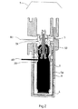
本発明は、添付の図面を参照すれば、さらによく理解されよう。添付の図面中、図1は、クラトン(登録商標)などのエラストマー材料で作られた容器の断面を示すもので、この容器には、単位分量の流体を配分するために使用され、合成樹脂製の支持体のなかに置かれたポンプを装備しており、この全体は本発明による充填装置のホルダーのなかに取り付けられている。
【0065】
【実施例】
図1では、全体が、中空針を貫通させるのに適しかつ中空針を抜き取った後にそれ自体が再び閉鎖するのに十分な弾力性を有する材料、ここではクラトン(登録商標)によって作られた容器1を見ることができるが、この容器は、貫通されそして補足的な厚さにより効果的に再び閉鎖するように特に設計された2つの部分2A、2Bを含む。
【0066】
容器1、すなわちクラトン(登録商標)でできた袋は、一方では、この室に充填される流体を後で分配することのできるポンプ3によって閉塞され、他方では、溶融によって行われる封止部4によって閉塞され、この容器1は堅固な合成樹脂でできた2つの部分5A、5Bから成るシェル5のなかに格納されており、このシェル5は前記の容器1を実質的に覆っている。
【0067】
全体は、本発明による方法を実施する目的のために、充填ユニットのホルダー6のなかに保持されている。7に、層流ガス束の到来が概示されており、この例では、この層流ガス束は充填ユニットとこれに含まれる針の全体を包む。これらの針はここでは箇所2A、2Bの左側に位置するが、ここでは図示しなかった。しかし図2では充填する状態にある。
【0068】
層流ガス束のために使用される滅菌フィルタは、「ULPA」の命名で知られている型式のもので、0.12ミクロンの開口を有し、この層流ガス束に、米国総務庁の連邦規格209、クラス10によって規定されている無菌性を保証し、すなわち、直径が0.12ミクロン以下の粒子を1立方メートル当り最高約350個しか通過させないフィルタである。
【0069】
図2では、容器1を横切る充填用中空針8Rと排出用中空針8Eを見ることができる。
【0070】
容器は、望まれるならば、たとえばガンマ線によって充填の前に滅菌を受けている。針の導入は、保持用ホルダ6が厚い部分2A、2Bのレベルを妨害しない箇所のレベルに行われる。
【0071】
充填の前に吸引ステップを実施する場合には、充填される前に、エラストマー製の容器はポンプとは反対の部分が偏平になる。
【0072】
この充填ステップは、充填の段階で形成されることになる気泡をすべて、排出用針が貫通している容器の頂部に上昇させるために、振動台の上で実施されることが好ましい。
【0073】
ここで先ず、バルブによって閉鎖され、中空針8Eによって貫通される容器のなかに含まれる流体の吸引を行ったが、この吸引によって、特にポンプ3のいろいろな空洞のなかに存在する流体を排除できた。次に中空針のために特に設計された部分2を横切って導入された中空針8Rを用いて充填を行ったが、ここでこの充填は部分的である。
【0074】
上記の例では、貫通を行うための2本の針の機械化された導入は、これらを引き抜く場合も同様に、同時に行われた。
【0075】
さらに、充填用の中空針8Rは、容器の頂部近くに導入される排出用の中空針8Eの下に位置する。
【0076】
次に針の引抜きを行い、望まれるならば、特に熱溶融による封止を行って気密化を行うが、これは図3において貫通のレベルで見ることができ、ここで針は、容器を溶融することによって貫通孔を確実に完全閉鎖させることを保証する加熱プラグ9A、9Bに置き代えられている。
【0077】
この封止は、長い期間にわたって容器を貯蔵することが特に問題となる場合に、本発明の方法と装置を特に興味あるものにする。
【0078】
その上に、この容器の全体に対して同一の材料を使用することは、本発明の方法と装置を価格の点で非常に競争力のあるものにしている。
【0079】
図2では、厚い部分2A、2Bが小さな中空円筒によって延長されているのがわかる。これらの円筒は都合よく、半球形ボタンのような、容器の外側に一種のこぶを形成する、もっと厚いものに置き代えることができる。
【0080】
したがって、加熱ジョーのヘッドは、たとえば加熱プラグ、加熱ドーム、または加熱コーンに置き代えることができる。
【0081】
さらに、変形として、層流束の供給を、密封通気フードの下で無菌状態でないものに行うことができ、この場合、この密封通気フードの下で上に述べた種々の操作のすべてまたは一部が行なわれる。この場合、作業スペースには操作者は滅菌手袋を用いてのみアクセスすることができる。
【0082】
この変形は都合よく、層流束の一時的な欠陥を回避できるようにし、また望むならば、この層流束のために、濾過の後に循環される不活性ガスを利用できるようにする。
【0083】
結果的に、本発明による方法は、特に無菌条件で充填を達成するためにわずかな操作ステップ数しか必要としない場合に、とりわけ有利であることが明らかになる。
【0084】
こうして、低いコストで実施することができ、しかも最高の安全性をもたらす方法が提供される。
【図面の簡単な説明】
【図1】クラトン(登録商標)などのエラストマー材料で作られた容器の断面であり、この容器には、単位分量の流体を配分するために使用され、合成樹脂製の支持体のなかに置かれたポンプを装備しており、この全体は本発明による充填装置のホルダーのなかに取り付けられている、前記の容器の断面図である。
【図2】常に同じ条件で、同じ要素、ならびに流体の注入及び閉鎖された密封袋のなかに先存する流体の吸引を示す図である。
【図3】同じ条件で、支持体のなかに入った容器を示し、全体が充填装置のホルダーのなかに取り付けられ、また充填用針と排出用針は引き抜かれており、代わりに、貫通開口のレベルで溶融によって完全な閉塞を行うことのできる加熱装置が取り付けられていることを示す図である。
【符号の説明】
1 容器
2A、2B 容器の部分
3 ポンプ
4 封止部
5 シェル
6 ホルダー
7 層流ガス束
8R 充填用中空針
8E 排出用中空針
9A、9B 加熱プラグ[0001]
[Industrial application fields]
The present invention relates to an industrial method for filling closed containers under aseptic conditions.
[0002]
[Prior art and problems to be solved by the invention]
The problem of rapidly industrially filling containers with fluids under aseptic conditions is of great importance in some industries, especially in the pharmaceutical industry.
[0003]
In fact, in medicine, injecting an individual into a fluid that contains a living organism of pathogenesis can have disastrous consequences.
[0004]
Already from French Patent Application No. 2509689, an apparatus and a method for reliably transferring a liquid in one container to another container in a sterilized manner are known, in which case the other container to be filled is known. Is placed in an airtight cylindrical chamber and water vapor is injected through a hypodermic needle to effect sterilization. Thus, a small bottle can be filled in half an hour using a certain predetermined needle.
[0005]
U.S. Pat. No. 2,550,066 discloses a method of filling a beverage container using a double needle injector, wherein sterilization of the interior of the container is performed by injecting steam.
[0006]
The misalignment between the filling and draining needles makes filling without gas residue (ie “airless”) impossible.
[0007]
International Patent Application No. 85/05269 describes, as its application subject, a method of manufacturing a syringe prefilled with unit quantities, as well as a device for carrying out this manufacturing method, in this case of capsules, And in some cases, the gas treatment of the injector is performed to generate a gas stream circulating from below to above that sweeps the outer wall of the capsule inside the cavity completely containing the capsule, and the swept gas flux through the injector tube To trigger.
[0008]
For this reason, it is possible to ensure maximum safety for filling containers intended to be dispensed in unit or multiple and repeated doses, especially without the use of preservatives. Always researched.
[0009]
Obviously, the greater the number of quantities to be allocated, the more this must be done with great care and especially quickly in the case of filling.
[0010]
For some products, it becomes clear that due to storage or possible degradation issues, and for hygienic reasons, it is very effective or indispensable for the filling step not to allow any fluid to come into contact with the air. Yes.
[0011]
Similarly, it is preferred that a desired fluid, such as a chemical, not be exposed to a sudden change in temperature or gas, no matter which step of the container filling operation.
[0012]
Furthermore, the filling is preferably carried out under conditions such that changes in the ambient temperature or pressure at the place where the filling is carried out do not affect the amount of pharmaceutical product distributed in the container. The amount is allocated using.
[0013]
Furthermore, similarly, it is preferable to prepare a method capable of filling a container without gas remaining.
[0014]
Finally, the filling must be performed where possible, where ambient air is necessarily sterile.
[0015]
[Means for Solving the Problems]
For this reason, what this application is directed to is an automated method for filling a closed container with fluid under aseptic conditions, said container penetrating a hollow needle. Including at least one part, made of a material that is sufficiently elastic so that it closes itself again after the hollow needle has been withdrawn,
-Through said part using a filling hollow needle to communicate with the fluid;
-Filling the container, characterized in that the piercing tip of the filling hollow needle is kept in aseptic conditions by laminar flux during these operations;
This is the method described above.
[0016]
The closure container can be of any kind. For example, it can be set as the following container.
[0017]
A glass bottle closed by a rubber stopper, eg shielded with a metal capsule, a container that can be completely penetrated, preferably filled with a gas or a gas mixture, or substantially as such In the form of a crushed sleeve, for example, a rubber bag made of a synthetic resin such as rubber, which is completely realized as one piece with the same material, or to be penetrated by a hollow needle Other types of containers suitable to contain at least one part, made of a material that is sufficiently elastic so that it closes itself again after the hollow needle has been withdrawn.
[0018]
The container is, more specifically, a synthetic resin bag that includes a side portion made of a material suitable for being pierced, said portion being thicker than the rest of the bag. It is preferable.
[0019]
The occlusion container can optionally be partially filled with other fluids or other fluids of the same nature.
[0020]
For example, a glass vial rubber material plug, particularly for injectable formulations, falls within the access zone as described above.
[0021]
The expression “closes again on its own” means that the interior of the container is substantially inaccessible to gases such as air and particles such as microorganisms, bacteria and viruses.
[0022]
The container or the entire interior of the container can be made of such a material.
[0023]
The container is, for example or preferably, made of an elastic material such as elastomer, kraton®, rubber, etc., obtained from a sealed elongated tube, especially hot, and cut with regular intervals and filled with gas Can be made into evacuated bags or vice versa. The container is quite specifically the container described below in the experimental part. A part of such a bag can be specifically designed to be penetrated by a hollow needle. This particular concept can in particular be a locally thickened material from which the bag is made, and this thick part is preferably located on the side.
[0024]
Such a thick part ensures, for example, that a complete closure is obtained, especially after the needle has been withdrawn, and on the other hand there is no risk of unwanted penetration, for example penetrating the opposite wall, only in one place. When guiding the filling hollow needle, the result that only one wall of the bag is penetrated can be facilitated.
[0025]
Suitable for piercing with a hollow needle, and with sufficient elasticity that the material itself closes again after the needle has been withdrawn, for example synthetic resin or rubber such as rubber or elastomer or especially Kraton (registered trademark) Material.
[0026]
As will be apparent to those skilled in the art, the thickness of the material at the penetration level is sufficient to effectively re-close the bag after the needle has been withdrawn, i.e., this thickness is actually It is selected in proportion to the diameter of the needle used and inversely proportional to the elasticity of the material.
[0027]
For containers having dimensions commonly used in the fields of pharmacy and medicine, this thickness is on the order of 2 mm. Considering the thickness to be penetrated, there is actually no upper limit for the thickness other than the upper limit required by the hardness of the hollow needle.
[0028]
The method according to the invention is preferably carried out at a rate that fills the entire vial in at least 10 seconds, and preferably fills the entire vial in 2 seconds, and more particularly a single bottle in 1 second. Thus, for example, it is understood that the same filling needle fills one new vial per second.
[0029]
The closure of the vial is preferably performed using techniques well known to those skilled in the art, such as applying a heating element, jaw or plug that melts at the perforation site. This closure is expediently performed using one or more laser beams concentrated at the penetration points. In this way, the energy required to melt the material constituting the part is limited to the perforated location.
[0030]
Under the preferred conditions of the above method, the filling needle (and possibly the draining needle as will be described later) is withdrawn and one or more through-sealings are performed rapidly, preferably immediately.
[0031]
The container can be of any kind of configuration, for example a bottle, ampoule, bottle, bag, sachet.
[0032]
Available filling hollow needles are well known to those skilled in the art. This needle is of the type commonly used for administering injectable preparations, for example, especially to humans, but has a large diameter, ie 0.6-3 mm, in particular 0.8-2 mm . The needle hole through which the fluid flows can also be a side hole.
[0033]
It is preferred to use needles that are well known to the expert in a form that does not remove the “punch” material or cause the formation of particles.
[0034]
Inside the hollow needle, fluids filling the container are connected. The injected fluid may be a solution, a suspension, or even a gas rather than a gel.
[0035]
The filling of the container is thus carried out according to methods well known to those skilled in the art, which are preferably automatic, for example by controlled and instantaneous pressure injection. In order to improve the filling so that no bubbles are formed, for example, the filling may preferably be carried out on a kind of shaking table.
[0036]
The essential feature of the above method is that the piercing hole tip of the filling hollow needle is aseptically obtained by pulsation of a gas bundle, in particular a laminar air bundle, at least at the level of the needle tip during any operation. It is to be maintained under. These laminar fluxes are well known in the current state of the art.
[0037]
From the laminar flux, as is well known, any element with a size below the cutoff of the selected filter is removed using at least one sterile microfilter or filter.
[0038]
The entire filling unit associated with the filling needle and the receiver that receives the bottle during filling is preferably under laminar flux suppression.
[0039]
As can be seen from the above, when only a small surface of the fluid is desired, the piercing tip of the filling hollow needle is in contact with the gas. This gas is normally the air coming out of the laminar flux generator.
[0040]
However, the laminar flux generator can be supplied with any gas, such as an inert gas, where even a very short contact between the fluid and air can cause undesirable results.
[0041]
Similarly, a gas flow of hydrogen peroxide (H 2 O 2 ) can be sent to the tip of the filling needle.
[0042]
In most cases in this case, it is preferable to be able to remove all or part of the fluid that may pre-exist in the sterile container, especially when the interior of the container is not substantially evacuated. In most cases, this fluid is from air.
[0043]
For this reason, what the present invention is directed to is a method as defined above, wherein the sterile container encloses another fluid, such as a gas or gas mixture, before filling, and also the material A part is pierced by the discharge hollow needle, a part of this material is suitable for penetrating the hollow needle, and after the hollow needle has been withdrawn, the part of the material itself is sufficiently resilient to close again. Wherein said part is the same as the part used in the filling, or preferably another part.
[0044]
Can be of the same type as used for filling, and its inside diameter is in some cases quite small, allowing penetration with a draining hollow needle to eliminate the fluid already present in the container Become. If desired, this can be done by simply injecting the fill fluid into the container. It is also possible to use a discharge device such as a pump so that this exclusion is performed simultaneously with filling. This draining can take place before, during or after filling.
[0045]
Conveniently, the ejection needle is at least 1 mm, preferably at least 5 mm, and more particularly at least 10 mm apart from the filling needle.
[0046]
In other preferred conditions for carrying out the method described above, the filling needle is in a lower position relative to the discharge needle during the filling operation. That is, it is preferable that the degree of separation is substantially the same as the above-mentioned separation. It is thus possible to carry out filling without leaving any gas in the container, ie "airless" filling.
[0047]
In this case, the penetration provided for the discharge is preferably performed near the end of the container, which is chosen to be the highest point of the container during filling.
[0048]
In yet another preferred condition for carrying out the method described above, the piercing tip of the filling hollow needle is likewise maintained in a sterile state.
[0049]
As can be seen from the above, the tip of the one or more needles is maintained in a sterile state, which is also applied at the penetration point of the container, at least when filled.
[0050]
However, aseptic conditions are also present at one or more penetrations of the container and, if necessary, at the tip of one or more hollow needles, i.e. at the critical interface level. It is preferable to apply.
[0051]
As will be apparent to those skilled in the art, if it is desired to obtain a container with sterile fluid as well as minimizing the contact of the fluid filling the container with air or other gases, fill the container. The closure container to be tried is itself sterile. This aseptic condition is well known to those skilled in the art, for example, depending on the nature of all or part of the container, radiation, especially gamma rays, beta rays, use of ethylene oxide, use of ultraviolet rays, use of electron flux Etc. can be realized.
[0052]
This sterilization is performed continuously between the coupling of the container and its filling, if desired.
[0053]
From this point of view, it is also possible to utilize means for indicating that sterilization is sufficient, for example colorimetric indicators sensitive to radiation and well known to those skilled in the art.
[0054]
As can be seen from the above, the above-described method is suitable for liquids that are filled with a fluid that is particularly sterile, does not contain any preservatives, or is fragile and is in danger of deterioration, particularly air or heat. This is a particularly interesting method.
[0055]
During the filling operation, the position of the needle and container depends on the purpose studied.
[0056]
If this position is not very important, the position of the needle or needles is pre-existing, for example, in the container, for example when it is desired to fill a bag in a substantially vacuum state. The results obtained when filling to ensure that all or nearly all of the fluid is removed can have a non-negligible effect.
[0057]
As can be easily understood, as indicated further above, for example, optional drainage occurs near the top of the container.
[0058]
A series of filling steps of the container can be as follows, for example. Attaching a container, starting a pump, introducing a hollow needle into one or more parts of the container suitable for the function of the container, opening a suction needle, opening a filling needle, filling, closing a suction needle, Withdraw these needles and seal the suction and filling ports if desired.
[0059]
The above steps can be used for aspiration and can accelerate filling, and if using two needles, then one pump for introducing fluid, air pre-existing in the container The case of using another pump for discharging fluid such as is shown.
[0060]
The start of these operations is clearly performed after the laminar flux generator has been started and the desired location (operation surface or enclosure, critical interface) has been sterilized.
[0061]
If desired, the penetrating tip of the aspiration needle can be equipped with a liquid sensitive unit so that both the filling function and the aspiration function are stopped when the detected level of filling is achieved.
[0062]
Another object of the present invention is to provide a method characterized in that it is preferable to close one or a plurality of points penetrated by a hollow needle by heat sealing or by laser beam utilization.
[0063]
Also intended by the present invention is an apparatus for carrying out the method as described above, at least an active laminar gas flux generator on the penetrating tip of the filling needle, filled with fluid during filling. Container holding means intended to be done, filling machine-driven hollow needle, if desired, a hollow needle moving on a discharge machine synchronized with the filling hollow needle in movement, holding the container Machine-moving means for moving the filling hollow needle in the direction of the means, a source of filling fluid in communication with the filling hollow needle, and, if desired, a container at a point penetrated by one or more needles Including the means for closing the device.
[0064]
The invention will be better understood with reference to the following drawings. In the accompanying drawings, FIG. 1 shows a cross section of a container made of an elastomeric material such as Kraton (registered trademark), which is used to distribute a unit amount of fluid and is made of a synthetic resin. Is mounted in a holder of the filling device according to the invention.
[0065]
【Example】
In FIG. 1, a container made entirely of material, here Kraton®, which is suitable for penetrating the hollow needle and is sufficiently elastic to itself close again after the hollow needle has been withdrawn As can be seen, this container comprises two
[0066]
The container 1, i.e. a bag made of Kraton (R), is on the one hand closed by a
[0067]
The whole is held in the
[0068]
The sterilization filter used for the laminar gas flux is of the type known by the name “ULPA” and has an opening of 0.12 microns, which is fed into the Federal Office of the United States General Administration. A filter that guarantees sterility as defined by Standard 209, Class 10, i.e., only allows up to about 350 particles per cubic meter to pass through particles with a diameter of 0.12 microns or less.
[0069]
In FIG. 2, the filling hollow needle 8R and the discharge hollow needle 8E across the container 1 can be seen.
[0070]
The container has been sterilized prior to filling, for example by gamma radiation, if desired. The introduction of the needle is performed at a level where the holding
[0071]
If the suction step is performed before filling, the elastomeric container is flattened on the opposite side of the pump before filling.
[0072]
This filling step is preferably carried out on a shaking table in order to raise all the bubbles that will be formed in the filling stage to the top of the container through which the discharge needle penetrates.
[0073]
Here, first, the fluid contained in the container which is closed by the valve and penetrated by the hollow needle 8E was sucked, but this fluid can eliminate the fluid which exists in various cavities of the
[0074]
In the above example, the mechanized introduction of the two needles for penetrating was performed simultaneously as well when pulling them out.
[0075]
Further, the filling hollow needle 8R is located under the discharge hollow needle 8E introduced near the top of the container.
[0076]
The needle is then withdrawn and, if desired, sealing is achieved, particularly by heat melting, to achieve airtightness, which can be seen at the level of penetration in FIG. 3, where the needle melts the container. Thus, the heating plugs 9A and 9B are ensured to ensure that the through holes are completely closed.
[0077]
This sealing makes the method and apparatus of the present invention particularly interesting where storage of the container over a long period of time is particularly problematic.
[0078]
Moreover, the use of the same material for the entire container makes the method and apparatus of the present invention very competitive in price.
[0079]
In FIG. 2, it can be seen that the
[0080]
Thus, the head of the heating jaw can be replaced by, for example, a heating plug, a heating dome, or a heating cone.
[0081]
Furthermore, as a variant, the laminar flux supply can be made under non-sterile conditions under a sealed ventilation hood, in which case all or part of the various operations described above under this sealed ventilation hood. Is done. In this case, the work space can only be accessed by the operator using sterile gloves.
[0082]
This variant advantageously makes it possible to avoid temporary defects in the laminar flux and, if desired, makes available an inert gas circulated after filtration for this laminar flux.
[0083]
As a result, the method according to the invention proves to be particularly advantageous, especially when only a few operating steps are required to achieve filling under aseptic conditions.
[0084]
Thus, a method is provided that can be implemented at low cost and provides the highest safety.
[Brief description of the drawings]
FIG. 1 is a cross section of a container made of an elastomeric material such as Kraton®, which is used to distribute a unit quantity of fluid and is placed in a synthetic resin support. Fig. 2 is a cross-sectional view of said container, equipped with a pump, which is mounted in a holder of a filling device according to the invention.
FIG. 2 shows the same elements, always in the same conditions, and the infusion of fluid and pre-existing fluid in a closed sealing bag.
FIG. 3 shows the container in the support under the same conditions, the whole being mounted in the holder of the filling device, and the filling and draining needles being withdrawn, instead of through openings It is a figure which shows that the heating apparatus which can perform complete obstruction | occlusion by melting at the level of is attached.
[Explanation of symbols]
DESCRIPTION OF SYMBOLS 1
Claims (10)
前記1つの部分(2B)が、流体に接続された、機械駆動される充填用中空針(8R)を用いて貫通され、
前記容器の他の部分(2A)が、前記機械駆動される充填用中空針(8R)から側方に離れた、機械駆動される排出用中空針(8E)により貫通され、前記機械駆動される充填用中空針(8R)及び排出用中空針(8E)の移動は、同期化されており、
前記容器に収容された他の流体が排出され、
前記容器(1)の充填が、前記他の流体の排出の前、後あるいはそれと同時に進められ、前記容器の前記1つの部分(2B)及び前記他の部分(2A)が、これらの作業中、層流束(7)によって無菌状態に保たれるのと同様、前記機械駆動される排出用中空針(8E)及び充填用中空針(8R)の穿孔先端も、該中空針の穿孔先端が容器(1)の外側に位置する場合に、それらの作業中、層流束(7)によって無菌状態下に保たれること
を特徴とする前記の方法。An automated method for filling a fluid in a closed container ( 1 ) under aseptic conditions, said closed container closing other fluids such as a gas or a gas mixture before filling , the closure container is made of sufficiently elastic material so that again by itself closes after pulling out the hollow needle (8R) can be through the addition pre-sterilized hollow needle (8R), at least Including one part (2B), the closure container is also remote from the one part (2B) and can pass through the discharge hollow needle (8E) and after drawing out the discharge hollow needle Has another part (2A) made of a material that is sufficiently elastic to close again on its own,
Said one part (2B) is pierced with a mechanically driven filling hollow needle (8R) connected to a fluid;
The other part (2A) of the container is penetrated by the mechanically driven discharge hollow needle (8E) laterally separated from the mechanically driven filling hollow needle (8R) and is mechanically driven. The movements of the filling hollow needle (8R) and the discharging hollow needle (8E) are synchronized,
The other fluid contained in the container is discharged,
The filling of the container (1) proceeds before, after or simultaneously with the discharge of the other fluid, and the one part (2B) and the other part (2A) of the container are in these operations, Just as maintained in a sterile condition by Soryutaba (7), piercing tip of the mechanical drive ejected hollow needle is (8E) and filling the hollow needle (8R) also has piercing tip of the hollow needle container when located outside the (1), in their work, said method comprising Rukoto kept under sterile condition by Soryutaba (7).
閉塞容器(1)が充填される間、充填中に形成され得るいかなる泡も除去するために、前記閉塞容器を振動させる手段と、
少なくとも、充填用中空針(8R)及び排気用中空針(8E)の穿孔先端上に作用する層流ガス束(7)発生器と、
充填用中空針(8R)及び排気用中空針(8E)を前記容器(1)の方向に作動させる 機械駆動手段とを含んでおり、
前記排出用中空針(8E)が前記充填用中空針(8R)から側方に離間しており、前記閉塞容器(1)の1つの部分(2B)が充填用中空針(8R)によって貫通され、該閉塞容器(1)の他の部分(2A)は、機械駆動される充填用中空針(8R)から側方に離れた、機械駆動される排気用中空針(8E)によって貫通されること、を特徴とする、請求項1から9のいずれか一項に記載の方法を実施するための装置。 A filling hollow needle (8R) in fluid communication with a source of filling fluid, and a discharge hollow needle (8E) whose movement is synchronized with the filling hollow needle (8R);
Means to vibrate the closure container to remove any bubbles that may form during filling while the closure container (1) is being filled;
A laminar gas flux (7) generator acting on at least the perforation tips of the filling hollow needle (8R) and the exhaust hollow needle (8E);
Mechanical drive means for actuating the filling hollow needle (8R) and the exhaust hollow needle (8E) in the direction of the container (1) ,
The discharge hollow needle (8E) is laterally separated from the filling hollow needle (8R), and one part (2B) of the closing container (1) is penetrated by the filling hollow needle (8R). The other part (2A) of the closure container (1) is penetrated by a mechanically driven exhaust hollow needle (8E) that is laterally separated from the mechanically driven hollow needle (8R). An apparatus for carrying out the method according to claim 1, characterized in that
Applications Claiming Priority (2)
| Application Number | Priority Date | Filing Date | Title |
|---|---|---|---|
| FR9405011 | 1994-04-26 | ||
| FR9405011A FR2719018B1 (en) | 1994-04-26 | 1994-04-26 | Method for filling a closed container under aseptic conditions. |
Publications (2)
| Publication Number | Publication Date |
|---|---|
| JPH0840494A JPH0840494A (en) | 1996-02-13 |
| JP3645002B2 true JP3645002B2 (en) | 2005-05-11 |
Family
ID=9462508
Family Applications (1)
| Application Number | Title | Priority Date | Filing Date |
|---|---|---|---|
| JP10242295A Expired - Lifetime JP3645002B2 (en) | 1994-04-26 | 1995-04-26 | Method for filling closed containers under aseptic conditions |
Country Status (13)
| Country | Link |
|---|---|
| US (1) | US5641004A (en) |
| EP (1) | EP0679574B1 (en) |
| JP (1) | JP3645002B2 (en) |
| KR (1) | KR100424827B1 (en) |
| AT (1) | ATE194113T1 (en) |
| AU (1) | AU1765495A (en) |
| BR (1) | BR9501779A (en) |
| CA (1) | CA2147414C (en) |
| DE (1) | DE69517627T2 (en) |
| DK (1) | DK0679574T3 (en) |
| ES (1) | ES2148452T3 (en) |
| FR (1) | FR2719018B1 (en) |
| PT (1) | PT679574E (en) |
Families Citing this family (58)
| Publication number | Priority date | Publication date | Assignee | Title |
|---|---|---|---|---|
| SE515221C2 (en) * | 1996-03-20 | 2001-07-02 | Scandimed Internat Ab | Process for making and installing a package with a sterile packaged container with sterile contents |
| US5749201A (en) * | 1996-08-19 | 1998-05-12 | Cochrane; Benjamin | Laser bonded tamper proof press-on cap and seal |
| US6254579B1 (en) | 1999-11-08 | 2001-07-03 | Allergan Sales, Inc. | Multiple precision dose, preservative-free medication delivery system |
| US7707807B2 (en) * | 2004-03-08 | 2010-05-04 | Medical Instill Technologies, Inc. | Apparatus for molding and assembling containers with stoppers and filling same |
| US6604561B2 (en) | 2000-02-11 | 2003-08-12 | Medical Instill Technologies, Inc. | Medicament vial having a heat-sealable cap, and apparatus and method for filling the vial |
| US7669390B2 (en) | 2004-03-08 | 2010-03-02 | Medical Instill Technologies, Inc. | Method for molding and assembling containers with stoppers and filling same |
| US7243689B2 (en) * | 2000-02-11 | 2007-07-17 | Medical Instill Technologies, Inc. | Device with needle penetrable and laser resealable portion and related method |
| US6524287B1 (en) | 2000-10-10 | 2003-02-25 | Advanced Medical Optics | Housing apparatus with rear activated return button for instilling a medication into an eye |
| CA2426182C (en) * | 2000-10-23 | 2007-03-13 | Py Patent, Inc. | Fluid dispenser having a housing and flexible inner bladder |
| US7331944B2 (en) | 2000-10-23 | 2008-02-19 | Medical Instill Technologies, Inc. | Ophthalmic dispenser and associated method |
| US6533764B1 (en) | 2000-11-06 | 2003-03-18 | Allergan, Inc. | Twist housing apparatus for instilling a medication into an eye |
| US6506183B2 (en) | 2001-02-02 | 2003-01-14 | Advanced Medical Optics | One shot actuation housing apparatus for instilling a medication into an eye |
| AU2001247981C9 (en) * | 2001-02-12 | 2006-11-16 | Medical Instill Technologies, Inc. | Medicament vial having a heat-sealable cap, and apparatus and method for filling the vial |
| US7186241B2 (en) * | 2001-10-03 | 2007-03-06 | Medical Instill Technologies, Inc. | Syringe with needle penetrable and laser resealable stopper |
| WO2003033363A1 (en) * | 2001-10-16 | 2003-04-24 | Medical Instill Technologies, Inc. | Dispenser with sealed chamber and one-way valve for providing metered amounts of substances |
| US7798185B2 (en) | 2005-08-01 | 2010-09-21 | Medical Instill Technologies, Inc. | Dispenser and method for storing and dispensing sterile food product |
| DE10210051B4 (en) * | 2002-03-07 | 2005-10-13 | Siemens Ag | Device for the electrochemical detection of a nucleotide sequence, analysis cassette for such a device and method for producing such an analysis cassette |
| EP1517834B1 (en) * | 2002-06-19 | 2012-05-23 | Medical Instill Technologies, Inc. | Sterile filling machine having needle filling station within e-beam chamber |
| WO2004014778A2 (en) | 2002-08-13 | 2004-02-19 | Medical Instill Technologies, Inc. | Container and valve assembly for storing and dispensing substances, and related method |
| CN101001782A (en) * | 2002-09-03 | 2007-07-18 | 因斯蒂尔医学技术有限公司 | Sealed containers and methods of making and filling same |
| ES2232269B1 (en) * | 2003-01-21 | 2006-03-01 | Grifols, S.A. | PROCEDURE FOR THE STERILE DOSAGE OF ROADS. |
| CN100526165C (en) * | 2003-01-28 | 2009-08-12 | 因斯蒂尔医学技术有限公司 | Medicament vial having a heat-sealable cap, and apparatus and method for filling the vial |
| GB0304386D0 (en) * | 2003-02-25 | 2003-04-02 | Glaxosmithkline Biolog Sa | Novel process |
| US7077176B2 (en) * | 2003-04-28 | 2006-07-18 | Medical Instill Technologies, Inc. | Container with valve assembly for filling and dispensing substances, and apparatus and method for filling |
| EP1636091A2 (en) | 2003-05-12 | 2006-03-22 | Medical Instill Technologies, Inc. | Dispenser and apparatus for filling a dispenser |
| DE602004031829D1 (en) | 2003-05-20 | 2011-04-28 | Collins | OPHTHALMIC DRUG DELIVERY SYSTEM |
| US8545463B2 (en) | 2003-05-20 | 2013-10-01 | Optimyst Systems Inc. | Ophthalmic fluid reservoir assembly for use with an ophthalmic fluid delivery device |
| US7226231B2 (en) * | 2003-07-17 | 2007-06-05 | Medical Instill Technologies, Inc. | Piston-type dispenser with one-way valve for storing and dispensing metered amounts of substances |
| US6883564B2 (en) * | 2003-07-22 | 2005-04-26 | Thomas M. Risch | Pressurizing system for a dispensing container |
| US7628184B2 (en) | 2003-11-07 | 2009-12-08 | Medical Instill Technologies, Inc. | Adjustable needle filling and laser sealing apparatus and method |
| US7264142B2 (en) | 2004-01-27 | 2007-09-04 | Medical Instill Technologies, Inc. | Dispenser having variable-volume storage chamber and depressible one-way valve assembly for dispensing creams and other substances |
| US7096896B2 (en) * | 2004-03-05 | 2006-08-29 | Medical Instill Technologies, Inc. | Apparatus and method for needle filling and laser resealing |
| FR2875431B1 (en) * | 2004-09-17 | 2006-12-01 | Saint Gobain Performance Plast | PROCESS, MANUFACTURING PLANT AND SILICONE ELASTOMER RESERVOIRS FOR CONTROLLED AND REGULAR RELEASE OF SUBSTANCES IN THE SURROUNDING ENVIRONMENT |
| MX2007003666A (en) * | 2004-09-27 | 2007-05-24 | Medical Instill Tech Inc | Laterally-actuated dispenser with one- way valve for storing and dispensing metered amounts of substances. |
| US7322491B2 (en) * | 2004-12-04 | 2008-01-29 | Medical Instill Technologies, Inc. | Method of using one-way valve and related apparatus |
| US7810677B2 (en) * | 2004-12-04 | 2010-10-12 | Medical Instill Technologies, Inc. | One-way valve and apparatus and method of using the valve |
| AU2006332049A1 (en) * | 2005-01-25 | 2007-08-23 | Medical Instill Technologies, Inc. | Container and closure assembly for a fat containing liquid product |
| BRPI0608419A8 (en) * | 2005-03-11 | 2018-04-03 | Medical Instill Tech Inc | APPARATUS AND METHOD FOR MOLDING AND FILLING A CONTAINER |
| WO2007047902A2 (en) | 2005-10-17 | 2007-04-26 | Medical Instill Technologies, Inc. | Sterile de-molding apparatus and method |
| US7484345B2 (en) * | 2005-11-28 | 2009-02-03 | Pdc Facilities, Inc. | Filling machine |
| MX2008013131A (en) * | 2006-04-10 | 2009-05-11 | Medical Instill Tech Inc | Ready to drink container with nipple and needle penetrable and laser resealable portion, and related method. |
| JP5566101B2 (en) | 2006-04-24 | 2014-08-06 | メディカル・インスティル・テクノロジーズ・インコーポレイテッド | Needle penetrable and laser resealable freeze-drying apparatus and related methods |
| US8356733B2 (en) * | 2006-09-08 | 2013-01-22 | Medical Instill Technologies, Inc. | Method for dispensing fluids |
| US8132695B2 (en) * | 2006-11-11 | 2012-03-13 | Medical Instill Technologies, Inc. | Multiple dose delivery device with manually depressible actuator and one-way valve for storing and dispensing substances, and related method |
| TWI472459B (en) | 2008-05-19 | 2015-02-11 | Melrose David | Headspace modification method for removal of vaccum pressure and apparatus therefor |
| BR112012011566A2 (en) * | 2009-10-09 | 2016-06-28 | Py Daniel C | co-molded locking device, one-way valves, variable volume storage chamber and related method |
| SG185436A1 (en) | 2010-05-07 | 2012-12-28 | Alps Llc | Dispensing machine valve and method |
| GB2487206B (en) * | 2011-01-12 | 2015-12-16 | White Horse Innovations Ltd | Nozzle for fluid container |
| US10028886B2 (en) * | 2011-05-17 | 2018-07-24 | Aktivax, Inc. | Filing system and methods for aseptic cartridge and dispenser arrangement |
| US20140231427A1 (en) * | 2011-10-13 | 2014-08-21 | Advanced Technology Materials, Inc. | Liner-based shipping and dispensing containers for the substantially sterile storage, shipment, and dispense of materials |
| KR101617228B1 (en) * | 2012-01-20 | 2016-05-02 | 닥터.피와이 인스터튜트, 엘엘씨 | Device with co-molded closure, one-way valve, variable-volume storage chamber and anti-spritz feature and related method |
| CA2870307C (en) | 2012-04-13 | 2017-07-25 | Dr. Py Institute Llc | Modular filling apparatus and method |
| US9415885B2 (en) | 2013-03-15 | 2016-08-16 | Dr. Py Institute Llc | Device with sliding stopper and related method |
| JP6396501B2 (en) * | 2014-05-10 | 2018-09-26 | ドクター ピー インスティチュート エルエルシー | Self-opening and closing filling needle, needle holder, filler, and method |
| US10807743B2 (en) * | 2015-09-30 | 2020-10-20 | Muffin Incorporated | Systems and methods for filling and sealing vials |
| DE102016119890A1 (en) * | 2016-10-19 | 2018-04-19 | Krones Aktiengesellschaft | Method and device for producing beverage containers with recooling and gas supply |
| MX2021005952A (en) * | 2018-11-26 | 2021-08-11 | Dispensing Tech Bv | System and method for dispensing a mixture of a liquid and an additive and cartridge for use therein. |
| DE102020129169A1 (en) * | 2020-11-05 | 2022-05-05 | Syntegon Technology Gmbh | Closing device for closing pharmaceutical containers |
Family Cites Families (12)
| Publication number | Priority date | Publication date | Assignee | Title |
|---|---|---|---|---|
| GB500354A (en) * | 1936-07-10 | 1939-02-01 | Sharp & Dohme Inc | Improvements in the preservation of desiccated biologically active substances in evacuated containers |
| US2503147A (en) * | 1944-12-21 | 1950-04-04 | Applezweig Norman | Carpule filling machine |
| US2855006A (en) * | 1955-12-16 | 1958-10-07 | Nat Phoenix Ind Inc | Beverage containers and method of filling the same |
| US3340671A (en) * | 1964-08-10 | 1967-09-12 | Carnation Co | Method of filling containers under aseptic conditions |
| BE741479A (en) * | 1969-11-10 | 1970-04-16 | ||
| US4250611A (en) * | 1979-04-19 | 1981-02-17 | Alza Corporation | Process for making drug delivery device with reservoir |
| FR2509689A1 (en) * | 1981-07-17 | 1983-01-21 | Ceca Sa | Steam sterilised tap for aseptic transfer of contained liquid to flask - uses hollow piston to locate flask and push it onto hypodermic needle |
| JPS61502099A (en) * | 1984-05-16 | 1986-09-25 | コスモノ−ル ソシエテ アノニム | Method and apparatus for manufacturing single-dose prefilled syringe |
| US4842028A (en) * | 1987-05-13 | 1989-06-27 | Baxter International Inc. | Fluid transfer apparatus |
| US5341854A (en) * | 1989-09-28 | 1994-08-30 | Alberta Research Council | Robotic drug dispensing system |
| US5129212A (en) * | 1990-11-08 | 1992-07-14 | Liqui-Box/B-Bar-B Corporation | Method and apparatus for automatically filling and sterilizing containers |
| US5411065A (en) * | 1994-01-10 | 1995-05-02 | Kvm Technologies, Inc. | Liquid specimen transfer apparatus and method |
-
1994
- 1994-04-26 FR FR9405011A patent/FR2719018B1/en not_active Expired - Fee Related
-
1995
- 1995-04-11 PT PT95400817T patent/PT679574E/en unknown
- 1995-04-11 DK DK95400817T patent/DK0679574T3/en active
- 1995-04-11 EP EP95400817A patent/EP0679574B1/en not_active Expired - Lifetime
- 1995-04-11 AT AT95400817T patent/ATE194113T1/en not_active IP Right Cessation
- 1995-04-11 DE DE69517627T patent/DE69517627T2/en not_active Expired - Lifetime
- 1995-04-11 ES ES95400817T patent/ES2148452T3/en not_active Expired - Lifetime
- 1995-04-19 US US08/424,932 patent/US5641004A/en not_active Expired - Lifetime
- 1995-04-20 CA CA002147414A patent/CA2147414C/en not_active Expired - Lifetime
- 1995-04-25 BR BR9501779A patent/BR9501779A/en not_active IP Right Cessation
- 1995-04-26 JP JP10242295A patent/JP3645002B2/en not_active Expired - Lifetime
- 1995-04-26 KR KR1019950009922A patent/KR100424827B1/en not_active IP Right Cessation
- 1995-04-26 AU AU17654/95A patent/AU1765495A/en not_active Abandoned
Also Published As
| Publication number | Publication date |
|---|---|
| DE69517627T2 (en) | 2001-03-01 |
| EP0679574A1 (en) | 1995-11-02 |
| PT679574E (en) | 2000-12-29 |
| FR2719018B1 (en) | 1996-07-12 |
| FR2719018A1 (en) | 1995-10-27 |
| KR950031009A (en) | 1995-12-18 |
| ATE194113T1 (en) | 2000-07-15 |
| EP0679574B1 (en) | 2000-06-28 |
| BR9501779A (en) | 1995-11-21 |
| DE69517627D1 (en) | 2000-08-03 |
| CA2147414A1 (en) | 1995-10-27 |
| US5641004A (en) | 1997-06-24 |
| ES2148452T3 (en) | 2000-10-16 |
| AU1765495A (en) | 1995-11-02 |
| KR100424827B1 (en) | 2004-05-24 |
| DK0679574T3 (en) | 2000-10-23 |
| CA2147414C (en) | 2007-06-26 |
| JPH0840494A (en) | 1996-02-13 |
Similar Documents
| Publication | Publication Date | Title |
|---|---|---|
| JP3645002B2 (en) | Method for filling closed containers under aseptic conditions | |
| JP4216467B2 (en) | Medical device assembly and packaging method | |
| RU2070056C1 (en) | Method of sterilization of medical instruments for injections containing a cylinder and piston | |
| JPH0349262B2 (en) | ||
| JPH0669475B2 (en) | Double chamber bottle | |
| JP2008517678A (en) | Method and apparatus for lyophilizing, reconstituting, and administering a reconstituted agent | |
| JPH08504353A (en) | Manufacturing method and manufacturing device for pre-filled sterilizing and discharging device | |
| SG192312A1 (en) | Adaptor for coupling to a medical container | |
| US5382406A (en) | Sterile filling method | |
| JP4536825B1 (en) | Manufacturing method of two-chamber type syringe for combined use and sleeve containing preparation | |
| EP0739638A1 (en) | Method of sterilizing prefilled syringe medicines | |
| FI81064C (en) | Sterilizable product channel, aseptic container filling procedure and aseptic filling and storage system | |
| JPH0788151A (en) | Drug-containing vessel | |
| JPS63248605A (en) | Germless filling method of fluid into bag | |
| JP2003093475A (en) | Medicine filling device, medicine filling method and method of manufacturing for medicine bag containing medicine | |
| JPS6144032B2 (en) | ||
| JP2003312602A (en) | Method of manufacturing sequence of containers already encasing liquid | |
| CA2128292A1 (en) | Sterile filling system | |
| MXPA00008780A (en) | Method for manufacturing, filling and packaging medical containers | |
| JP2698524C (en) |
Legal Events
| Date | Code | Title | Description |
|---|---|---|---|
| A131 | Notification of reasons for refusal |
Free format text: JAPANESE INTERMEDIATE CODE: A131 Effective date: 20040615 |
|
| A601 | Written request for extension of time |
Free format text: JAPANESE INTERMEDIATE CODE: A601 Effective date: 20040909 |
|
| A602 | Written permission of extension of time |
Free format text: JAPANESE INTERMEDIATE CODE: A602 Effective date: 20040914 |
|
| A521 | Request for written amendment filed |
Free format text: JAPANESE INTERMEDIATE CODE: A523 Effective date: 20041214 |
|
| TRDD | Decision of grant or rejection written | ||
| A01 | Written decision to grant a patent or to grant a registration (utility model) |
Free format text: JAPANESE INTERMEDIATE CODE: A01 Effective date: 20050125 |
|
| A61 | First payment of annual fees (during grant procedure) |
Free format text: JAPANESE INTERMEDIATE CODE: A61 Effective date: 20050202 |
|
| R150 | Certificate of patent or registration of utility model |
Free format text: JAPANESE INTERMEDIATE CODE: R150 |
|
| FPAY | Renewal fee payment (event date is renewal date of database) |
Free format text: PAYMENT UNTIL: 20080210 Year of fee payment: 3 |
|
| FPAY | Renewal fee payment (event date is renewal date of database) |
Free format text: PAYMENT UNTIL: 20090210 Year of fee payment: 4 |
|
| FPAY | Renewal fee payment (event date is renewal date of database) |
Free format text: PAYMENT UNTIL: 20100210 Year of fee payment: 5 |
|
| FPAY | Renewal fee payment (event date is renewal date of database) |
Free format text: PAYMENT UNTIL: 20100210 Year of fee payment: 5 |
|
| FPAY | Renewal fee payment (event date is renewal date of database) |
Free format text: PAYMENT UNTIL: 20110210 Year of fee payment: 6 |
|
| FPAY | Renewal fee payment (event date is renewal date of database) |
Free format text: PAYMENT UNTIL: 20110210 Year of fee payment: 6 |
|
| FPAY | Renewal fee payment (event date is renewal date of database) |
Free format text: PAYMENT UNTIL: 20110210 Year of fee payment: 6 |
|
| FPAY | Renewal fee payment (event date is renewal date of database) |
Free format text: PAYMENT UNTIL: 20110210 Year of fee payment: 6 |
|
| FPAY | Renewal fee payment (event date is renewal date of database) |
Free format text: PAYMENT UNTIL: 20120210 Year of fee payment: 7 |
|
| FPAY | Renewal fee payment (event date is renewal date of database) |
Free format text: PAYMENT UNTIL: 20120210 Year of fee payment: 7 |
|
| FPAY | Renewal fee payment (event date is renewal date of database) |
Free format text: PAYMENT UNTIL: 20120210 Year of fee payment: 7 |
|
| FPAY | Renewal fee payment (event date is renewal date of database) |
Free format text: PAYMENT UNTIL: 20120210 Year of fee payment: 7 |
|
| FPAY | Renewal fee payment (event date is renewal date of database) |
Free format text: PAYMENT UNTIL: 20130210 Year of fee payment: 8 |
|
| FPAY | Renewal fee payment (event date is renewal date of database) |
Free format text: PAYMENT UNTIL: 20130210 Year of fee payment: 8 |
|
| FPAY | Renewal fee payment (event date is renewal date of database) |
Free format text: PAYMENT UNTIL: 20130210 Year of fee payment: 8 |
|
| FPAY | Renewal fee payment (event date is renewal date of database) |
Free format text: PAYMENT UNTIL: 20130210 Year of fee payment: 8 |
|
| FPAY | Renewal fee payment (event date is renewal date of database) |
Free format text: PAYMENT UNTIL: 20130210 Year of fee payment: 8 |
|
| FPAY | Renewal fee payment (event date is renewal date of database) |
Free format text: PAYMENT UNTIL: 20140210 Year of fee payment: 9 |
|
| R250 | Receipt of annual fees |
Free format text: JAPANESE INTERMEDIATE CODE: R250 |
|
| R250 | Receipt of annual fees |
Free format text: JAPANESE INTERMEDIATE CODE: R250 |
|
| EXPY | Cancellation because of completion of term |