JP3640964B2 - Fast multiwavelength illumination source in quantitative luminescence ratio microscopy - Google Patents
Fast multiwavelength illumination source in quantitative luminescence ratio microscopy Download PDFInfo
- Publication number
- JP3640964B2 JP3640964B2 JP52516795A JP52516795A JP3640964B2 JP 3640964 B2 JP3640964 B2 JP 3640964B2 JP 52516795 A JP52516795 A JP 52516795A JP 52516795 A JP52516795 A JP 52516795A JP 3640964 B2 JP3640964 B2 JP 3640964B2
- Authority
- JP
- Japan
- Prior art keywords
- light
- wavelength
- light source
- emission
- sample
- Prior art date
- Legal status (The legal status is an assumption and is not a legal conclusion. Google has not performed a legal analysis and makes no representation as to the accuracy of the status listed.)
- Expired - Lifetime
Links
Images


Classifications
-
- G—PHYSICS
- G01—MEASURING; TESTING
- G01N—INVESTIGATING OR ANALYSING MATERIALS BY DETERMINING THEIR CHEMICAL OR PHYSICAL PROPERTIES
- G01N21/00—Investigating or analysing materials by the use of optical means, i.e. using sub-millimetre waves, infrared, visible or ultraviolet light
- G01N21/62—Systems in which the material investigated is excited whereby it emits light or causes a change in wavelength of the incident light
- G01N21/63—Systems in which the material investigated is excited whereby it emits light or causes a change in wavelength of the incident light optically excited
- G01N21/64—Fluorescence; Phosphorescence
- G01N21/645—Specially adapted constructive features of fluorimeters
- G01N21/6456—Spatial resolved fluorescence measurements; Imaging
- G01N21/6458—Fluorescence microscopy
-
- G—PHYSICS
- G01—MEASURING; TESTING
- G01N—INVESTIGATING OR ANALYSING MATERIALS BY DETERMINING THEIR CHEMICAL OR PHYSICAL PROPERTIES
- G01N21/00—Investigating or analysing materials by the use of optical means, i.e. using sub-millimetre waves, infrared, visible or ultraviolet light
- G01N21/62—Systems in which the material investigated is excited whereby it emits light or causes a change in wavelength of the incident light
- G01N21/63—Systems in which the material investigated is excited whereby it emits light or causes a change in wavelength of the incident light optically excited
- G01N21/64—Fluorescence; Phosphorescence
- G01N21/6428—Measuring fluorescence of fluorescent products of reactions or of fluorochrome labelled reactive substances, e.g. measuring quenching effects, using measuring "optrodes"
-
- G—PHYSICS
- G01—MEASURING; TESTING
- G01N—INVESTIGATING OR ANALYSING MATERIALS BY DETERMINING THEIR CHEMICAL OR PHYSICAL PROPERTIES
- G01N21/00—Investigating or analysing materials by the use of optical means, i.e. using sub-millimetre waves, infrared, visible or ultraviolet light
- G01N21/62—Systems in which the material investigated is excited whereby it emits light or causes a change in wavelength of the incident light
- G01N21/63—Systems in which the material investigated is excited whereby it emits light or causes a change in wavelength of the incident light optically excited
- G01N21/64—Fluorescence; Phosphorescence
- G01N2021/6417—Spectrofluorimetric devices
- G01N2021/6419—Excitation at two or more wavelengths
Abstract
Description
技術分野
本発明は、高速多重波長照明源、照明源を具備する装置、照明源および装置を使用する定量比率ルミネセンス顕微鏡法(quantitative ratio luminescence microscopy)の発光サンプルを照射する方法に関する。
発明の背景
定量蛍光顕微鏡法で拡大しつつある分野が、2つ以上の光の波長で検体の同じフィールドを連続的に照らし出し、各イメージを捕捉してから、2つの結果として生じるイメージ(あるいはイメージ内での関心のある領域)の強度を分割し、2つのイメージの強度率を求めることを必要とする比率イメージングである。典型的なケースでは、検体は蛍光染料により分類され、その蛍光率は染料の定量特性または蛍光染料の蛍光性に影響を及ぼす別の物質との相互作用と関係付けられる。多重放出率測光法および多重放出比率イメージング用の方法および装置の一例は、1992年8月26日に提出された米国出願番号07/935,873、現在は1994年7月26日に発行された米国特許第5,332,905号に記述され、その全内容は参照により本明細書中に取り入れられている。
定量蛍光比率イメージングまたは(「定量比率イメージング」または「定量比率測光法」としても既知の)蛍光比率測光法において、蛍光化合物または種を含有する検体は、2つの異なる波長の光(λ1およびλ2)により照らし出される。その結果生じる各蛍光強度(I1およびI2)が、測光器により蛍光検体上の関心のある事前に決定された任意の数の領域で測定される。代わりに、蛍光強度I1およびI2は、蛍光検体のイメージの作成または観察、あるいはその両方を行うことができるように、イメージング検出器により1列のピクセルとして検出することもできる。
2つのそれぞれの励起波長λ1およびλ2のそれぞれでの蛍光放出強度の比率(I1/I2)の関係性は、蛍光染料と関連または相互作用する物質の濃度の関数である。蛍光性に影響を及ぼす物質([物質])は、以下に示す等式(1)により定義される。

もう一つの方法は、サンプル上に焦点が合った2つの光源の単色光の間で交番する方法である。これは、現在では、図2に示されるように、2つの光源22と23および検体24の間に配置される機械的手段21により達成される。機械的手段21は、一般的には、シャッターを交互に開閉するか、チョッパー・ホイールを回転させることのどちらかにより、光の1つのビームを選択式で遮る。光ビームは、機械的手段21を通過した後、検体24を照射する前にフィルター25または26を通過する。
フィルター・ホイール、シャッターまたはチョッパー・ブレードを利用するアプローチは、フィルター、シャッター、チョッパー・ブレードを変更するのに必要となる機械的な運動の速度により制限を受ける。対照的に、新しい測定を行ったり新しい測定を処理するために検出器を交番する速度は、測定装置を制御する電子回路によってのみ制限される。一般的に、電子インパルスは、フィルター・ホイール、シャッター、またはチョッパー・ブレードのような機械的装置よりかなり高速な速度で変化できる。したがって、測光技術においては、機械的な運動の速度でではなく、電子回路の速度で異なる波長の光源を(繰り返し)変更するまたは異なる波長の光源間で切り換えるための手段の実現が望ましい目標となる。
さらに、機械的に切り替わるフィルター、シャッター、またはチョッパー・ブレードは、測定装置の振動も引き起こす。このような振動は、(特に検体が顕微鏡の下で見られている場合に)測定中のサンプルの位置の変化につながり、それにより測定から求められるデータの信頼性を破壊する可能性がある。
現在利用できる最高速度のフィルター・ホイールは、異なる励起波長間の切り替えを約2.5−5ミリ秒(ms)からの時間期間で行う機能を提供する。しかしながら、このようなフィルター・ホイールは動作中一定運動を行う。一定運動は、サンプルを照射できる期間を制限するだけではなく、励起光をフィルターする上で非均一な干渉パターンを生じさせる。
発明の開示
したがって、本発明の第1の目的は、光の2つの波長の間で変更するための電子手段を具備する新規の照明源を提供することである。
本発明のさらなる目的は、照明源を具備する発光サンプルを照射するための新規装置を提供することである。
本発明のさらなる目的は、照明源および装置を使用する発光放射比率測光法および多重放出比率イメージングの新規の方法を提供することである。
本発明のさらなる目的とは、フィルター・ホイール、フィルター・アーム、チョッパー・ホイール、および照射の波長あるいは励起光の波長を変更するためのそれ以外の過去の装置に固有な振動というリスクが生じるのを回避する放出比率イメージングおよび放出比率測光法を実施するための新規の方法および装置を提供することである。
本発明のさらなる目的とは、異なった波長、または機械的な切換装置により制限されない速度での光の強度、あるいはその両方の間での切り替えを可能にする、サンプルを照射するための新規の方法および装置を提供することである。
本発明のさらなる目的とは、ミリ秒およびミリ秒以下の規模で発光物質と発光性に影響を及ぼす物質(を含む運動現象)の間の相互作用の変化をモニターすることができる発光放出比率測光およびイメージングを実施するための新規の方法および装置を提供することである。
本発明のさらなる目的とは、ミリ秒およびミリ秒以下の規模で蛍光物質とルミネセンスに影響を及ぼす物質を含む運動現象をモニターすることができる、蛍光放出比率測光法およびイメージングを実施するための新規の方法および装置を提供することである。
本発明のそれ以外のさまざまな目的、特徴および付随する優位点は、類似する参照文字がいくつかの図面全体で類似する部分または対応する部分を指定し、実施例の次に示す詳細な記述が、前記の問題を克服する本発明により提供されている、付随の図面に関連して考慮される場合に、以下の詳細な記述から同発明がさらによく理解されるに従い、より完全に認識される。
【図面の簡単な説明】
本発明および付随するその優位点のより完全な理解は、同発明が、付随する図面に関連して考慮される場合に以下の詳細な説明を参照することによりさらによく理解されるに従い、容易に得られるであろう。
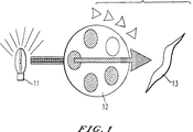
図1は、フィルター・ホイールを使用することにより照射の波長を変更する従来の方法を図解する。
図2は、シャッターまたは回転するチョッパー・ホイールを使用して照射の波長を変更する従来の方法を図解する。
図3は、2つの独立した光源を電子的に制御することにより励起エネルギーの波長を変更する方法を図解する。
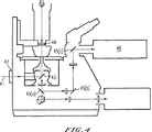
図4は、放出比率測光法または放出比率イメージングあるいはその両方を実施するための装置の概要図である。
図5は、多重アーク切り替え源の性能特性を図解する。
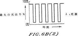
図6Aおよび図6Bは、電子制御および切り替えの結果として、2つの独立した光源のそれぞれのアーク電流および光出力の変化を図表で描画する。
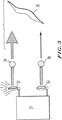
図7は、アーク電流と光強度の間の一般的な関係性を図解する。
図8は、ビーム結合装置と組み合わせた本発明の照明源の代替実施例を図解する。
図9は、パイロット・アークおよび運転アークを利用する多重アーク・ランプを具備する本発明の照明源の代替実施例を図解する。
発明を実施するための最良の形態
類似する参照数字が、複数の図面で同一部分または対応する部分を示す図面、さらに特定するとその図3を参照すると、本発明の方法の光の2つの異なる波長でサンプルを連続して照射する方法および方法に適した装置の第1ステップが、静的に図解されている。図3では、電子電流制御手段31は、第1光源32に対し比較的高い電流を提供する。第1光源32は、第1波長特殊フィルター34を通過する励起光を提供し、それから発光(蛍光性であることが望ましい)物質を含有する検体36に当たる(または照射する)第1波長λ1の光を生成する。と同時に、相対的に低い電流が、第2光源33に対し電子電流制御手段31により提供される。電流の第2光源33に対する相対的な割合は、第1波長λ1の励起光での照射により引き起こされ、第1光源32および第1波長特殊フィルター34により生成される、検体36の発光放出(複数の場合がある)に干渉しない、あるいは検体36の発光放出(複数の場合がある)に影響を及ぼさないほど十分に低い。
技術において理解されているように、光のエネルギーはその波長に反比例する。用語「エネルギー」および「波長」は、光に関しては取り換えて使用できる。さらに用語「発光」および「ルミネセンス」は、両方とも蛍光性の現象および燐光性の現象を指す。
励起光の波長を変更するためには、電子電流制御手段31は、それぞれの光源(例えば、アーク・ランプ32および33)を通って流れる電流の相対量を交互に変更する。その結果、電子電流制御手段31は、第1光源32および第2光源33の強度も交互に変更する。図3に示される第1ステップから、第2光源33を通って流れる電流を増大させ、第1光源32を通って流れる電流を減少させることにより、サンプル36に当たる光の波長が変化する。
このようにして電流を変更すると、各光源の光強度の瞬間的な変化が引き起こされる。2つの源を使用するシステムのケースでは、電流が(λ1を制御する)第1ランプ32で増加し、電流が(λ2を制御する)第2ランプ33で減少すると、その結果生じる効果は、λ1光で検体36を照明することである。それから電流が(λ2を制御する)第2ランプ33で上昇し、電流が(λ1を制御する)第1ランプ32で減少すると、その結果として生じる効果は、λ2光で検体36を照明することである。その結果、光のこれらの2つの波長で検体を交互に照らし出すために、電子電流制御手段31が提供することができる周波数でサイクルを繰り返すことができる。
また、光の異なる波長を変更したり、光の異なる波長の間で切り替えるための前記の同じ方法で、第1光源および第2光源により生成される光の異なる強度を変更したり、第1光源および第2光源により生成される光の異なる強度の間で切り替える、あるいはその両方を行うこともできる。したがって、光の異なる強度を変更したり、光の異なる強度間で切り替えたり、あるいはその両方を行う場合には、第1光源および第2光源、ならびにそれと関連するあらゆる波長選択手段により提供される第1光ビームおよび第2光ビームは、同じである場合(λ1=λ2)もあれば、異なる場合(λ1≠λ2)もある。
したがって、本発明のある面は、
(A)第1波長、第1強度、または第1波長と第1強度の両方を有する光で前記サンプルを照射するステップと、
(B)第2波長、第2強度、または第2波長と第2強度の両方を有する光で、前記照射ステップ(A)の1ナノ秒(1ns)から1秒(1s)の時間期間内で前記サンプルを照射するステップと、
から構成される、サンプルを照射する方法に関する。
便宜上、以下の説明(複数の場合がある)では、同じ技法は、光の異なる強度へ変更したり、光の異なる強度の間で交互に切り替えたりすることにも適用できるが、光の異なる波長を変更したり、光の異なる波長の間で交互に切り替えたりするための方法および装置に集中する。
本発明のサンプルを照射する方法の照射ステップ(A)は、第1値を有する電流に第1光源を通過させることを含むのが望ましく、照射ステップ(B)は、第2値を有する電流に第2光源を通過させることを含むのが望ましい。照射ステップ(A)は、第3値が電流の第2値を下回る、第3値を有する電流に第2光源を通過させることも含み、照射ステップ(B)が、第4値が電流の第1値を下回る、第4値を有する電流に第1光源を通過させることも含むのが更に望ましい。
本発明の別の面では、サンプルを照射する方法は、照射ステップ(A)の後で、照射ステップ(B)の前に、
(A‘)第1光源の電流の第1値を電流の第4値まで減少させるステップと、
(A“)第2光源の電流の第3値を電流の第2値まで増大させるステップと、
をさらに具備する。
本発明のさらに別の面では、サンプルを照射する方法の高速かつ正確な反復性が優位に利用されている。したがって、方法は、さらに、照射ステップ(B)の後の1nsから1sの時間期間内で、照射ステップ(A)を反復することを含む。
本発明のさらに別の面は、
(A)第1波長、第1強度、または第1波長と第1強度の両方を有する第1光ビームを生成する第1光源と、
(B)第2波長、第2強度、または第2波長と第2強度の両方を有する第2光ビームを生成する第2光源であって、前記第2波長が前記第1波長と異なるか、前記第2強度が前記第1強度と異なるか、あるいは前記第2波長および前記第2強度が前記第1波長および第1強度と異なる第2光源と、
(C)前記第1光源および前記第2光源のそれぞれに対する電流を制御するための制御手段であって、前記制御手段が第1光源および第2光源に電気的に接続されている制御手段と、
を具備する、2つまたはそれ以上の波長、強度、あるいは光の波長と強度でサンプルを連続して照射するための装置に関する。
光の第1波長および第2波長のそれぞれは、光の波長のバンドまたは範囲の中間波長あるいは平均波長(例えば、300nmから340nmあるいは380nmから400nm)を表すか、あるいは選択されたまたは希望の波長より大きなバンドまたは範囲[例えば、500nmまたはそれ以上の波長を持つ光が通過できるようにする長パス・フィルターのような「長パス・フィルター」]を表す場合がある。したがって、本発明の装置は、さらに、光のバンドを選択するための第1手段および第2手段も具備し、その場合、手段は、フィルター、回折格子モノクロメーター、あるいは光の波長の選択されたバンドを実現するそれ以外の同等な装置である可能性がある。本発明の光のバンドを選択するための手段は、光源により生成された後で、サンプルに当たるまたはサンプルを照射する前に、各光ビームを遮る。
任意のバンド幅を持つ光のバンドを選択できるが、波長の第1バンドおよび第2バンドのそれぞれが40nmまたはそれ以下の帯域幅となるか、あるいは希望の波長または選択された波長より大きいか、希望の波長または選択された波長に等しくなることが望ましい。このような光の波長のバンドは、それぞれが第1光源および第2光源により生成される光の経路内に配置される第1フィルターおよび第2フィルターにより実現される。このようなフィルターは、任意の数の適切な従来の波長選択物質からできている可能性があり、一般的に技術で既知である。代わりに、希望の励起波長を提供する従来の回折格子モノクロメーターが、第1フィルターおよび第2フィルターのどちらかまたは両方の代わりに使用される場合がある。このようにして、優位な実施例においては、本発明の装置が、光の2つまたは3つ以上の波長でサンプルを照射する。第1波長は、波長の第1バンドの中間波長または平均波長であり、第2波長は、波長の第2バンドの中間波長または平均波長であり、波長の第1バンドおよび第2バンドのそれぞれは、(a)40nmまたはそれ以下の帯域幅となるか、(b)希望の波長または事前に選択された波長を上回るか、希望の波長または事前に選択された波長と等しくなる。
本発明の別の面では、サンプルを光の2つまたは3つ以上の波長で連続して照射するための装置での第1光源(A)は第1アークであり、第2光源(B)は第2アークである。装置の1つの実施例では、第1アークは第1アーク・ランプであり、第2アークは第2アーク・ランプである。
本発明では、サンプルにおいて任意の数の発光放出を作成するために十分な励起光を提供するアーク・ランプが使用されることがある。光源は、例えば10Wから2000Wのワット数のアーク・ランプである場合がある。適切なアーク・ランプの選択は、必要となる照明(励起光)の量、光源により作り出される光の強度、またはそれ以外の関連する要因(複数の場合がある)、あるいはそのすべてに基づいて決定される。本発明による装置および方法の1つの優位点は、利用できる光源の柔軟性にある。例えば、第1源を光の第1強度を提供するアーク・ランプ(例えば、500ワット(W)のアーク・ランプ)とし、第2光源が光の第2の相対的に高い強度または相対的に低い強度(例えば、10Wまたは2000Wのアーク・ランプ)を提供する場合がある。
本発明の方法および装置の別の優位点とは、光の2つの異なる波長でサンプルを同時に照射できるという点である。例えば、第1光源は、発光化合物または染料を励起する照射光の第1波長を実現し、第2光源が技術(Ann.Rev.Biophys.Chem.,第18巻、239頁(1989年)のJ.A.マックレイ(McCray)その他、およびオレゴン州、ジャンクション・シティーにある分子プローブ社(Molecular Probe)により配布されるカタログの品目番号4287を参照のこと)で既知の方法で光活性化可能なケージに入れられた(caged)プローブを「アンケージ(uncage)する」か、起動するために照射光の第2波長を提供することができる。代わりに、第1光源が、光の第1波長でサンプルの連続照射を行い、第2光源がサンプルの間欠照射を行う(例えば「点滅」照射)場合がある。したがって、本発明の方法は、照射ステップの任意の特定な時相シーケンスに制限されない。
本発明は、2つ以上の光源および2つ以上の光の波長を含むように拡張されることもある。理論的には、生成される光ビームが照射のためにサンプルに向けることができる限り、光源の数に制限は存在しない。同様に、選択された波長のそれぞれを、サンプルを照射するために作り出し使用できる限り、選択可能な光の波長の数に制限はない。
図4は、放出比率測光法またはイメージングを実施するためのある特定な装置の典型的な図を示す。光源41は、希望の放出現象を生じさせるために、適切な励起エネルギーの光を提供する。本発明では、光源41は、電子電流制御手段31および第1光源32と第2光源33を具備する図3に図示される装置であるのが望ましい。光源41からの光は(図3に図示されるように、第1フィルター34および第2フィルター35を具備することがある)濾過装置42を通過してから、二色性ミラー43によりサンプル取付け領域または取付けプラットホーム44に向かって反射される。それから、励起光は取付けプラットホーム44上に配置または取り付けられたサンプルにより吸収される。サンプルは、発光(蛍光性または燐光性)物質または発光合成物を含有し、合成物は、発光物質および発光性に影響を及ぼす種類を含む。発光物質または合成物は、励起状態になり、その後励起光より低いエネルギーで、長い波長の光を放出する。発光物質から放出される光は、二色性ミラー43を通過し、放出が測定される検出器46に向かって、一連のミラー45(a)、45(b)、および45(c)により反射される。
それから、第2放出を得るために、プロセスが繰り返される。任意の数の追加発光物質または合成物を有するサンプルの場合、プロセスは追加発光物質または合成物ごとにさらに二度繰り返される。放出のそれぞれが、適切に装備された検出器により個別にモニターされる。
本発明に従って、光波長を変更するためのこのような機械的な装置は、本発明の慣行には使用されないという点は除くが、任意の数のランプ源が、シャッターまたはチョッパーを使用して前記の従来の方法(複数の場合がある)でのように検体を照らし出すことができるように配置される。
図5に図解されるように、励起光の第1波長(λ1)から励起光の第2波長(λ2)への変更は、電子電流制御手段51を使用して電子的に達成される。電流を光源に制御する制御手段が、ソリッド・ステートの電子回路により提供されるのが望ましい。
図5により示される静的図解では、電子電流制御手段51は、この静的図解では活性光源である第1光源52に対して相対的に高い電流を提供する。例えば、第1光源に流れる電流の相対パーセンテージは、電子電流制御手段51により第1光源52および第2光源53の両方に供給される総電流の>90%となることがある。不活性光源を通して小さな電流を維持することの方が望まれることを考えると、電流の活性光源に対する最大相対パーセンテージは、すべての光源に対して電子電流制御手段により供給される総電流の95%から99%となるのが望ましい。したがって、図5の静的な図解においては、第1光源52に対して供給される電流の相対パーセンテージは、第1光源52および第2光源53の両方に電子電流制御装置51により供給される総電流の、95−99%となるのが望ましく、第2光源53に供給される電流の相対パーセンテージは1−5%となるのが望ましい。
第1光源52は、第1波長特殊フィルター54を通過する第1光ビームを提供し、それから第1検出器56にあたる第1波長λ1の光を生成する。同時に、相対的に低い電流が、第2波長特殊フィルター55を通過する第2光ビームを提供し、それから第2検出器57にあたる第2波長λ2の光を生成する。
励起光の異なる波長の間で切り替えを行うために、電子電流制御手段51は、各光源52および53を通って流れる電流の量を交互に変更することによって、各光源52および53の相対強度を交互に変更する。光源52および53は、例えば、アーク・ランプである。光源53を通って流れる電流を増大させ、第1光源52を通って流れる電流を減少させることによって、第1検出器56および第2検出器57にあたる光の各波長の強度は、互いに対して変化する。代わりに、あるいはさらに、電子電流制御手段51を使用することによって、励起光の異なる強度を切り替え、各光源52および53を通って流れる電流の相対量を交互に変更することができる。
光源(例えば、アーク・ランプ)の強度が減少状態にあるときには、光源で最小の電流を維持することが優位である。光源の、およびさらに特定するとアーク・ランプでの「最小電流」とは、小さなアークをサポートするのに十分な電流ではあるが、相対的に大きな電流にそれを通過させる光源からの光での照射から生じる放出の測定との干渉を生じさせない電流のことである。最小電流で動作するアークを「パイロット」状態にあると考えることができる。ランプにかけられる最大電流の最低1%またはそれ以下の電流でアークを活性状態で維持できる。アークが活性状態である限り、増大した電流をかけると瞬間的に新しいレベルの照明になる。パイロット状態にあるアークが消えてしまうと、高速切り替えは可能ではない。アークを確立し直すには、比較的に長い時間量(例えば、約1−20秒)が必要である。
パイロット状態にアークを維持すると、新しく安定した光の強度を瞬間的に確立することが容易になる。新しい強度の安定性および再現性は、発光種または発光性に影響を及ぼす種の未知の濃度分布を含むサンプルの放出強度を照射または測定する前に、適切な基準により校正することにより優位に強化できる。したがって、アーク・ランプ源は、瞬間的な非機械的な振動を免れた電子制御という重要な特徴により、高速切り替えされる光強度の幅広い動的な範囲を実現するために優位に利用できる。
図5に示されるように、電流の相対的に高い割合および相対的に低い割合が、第1光源52と第2光源53の間で交番され、生成される各光ビームの強度は、第1検出器56および第2検出器57でモニターされ、図6Aおよび図6Bに示される光対時間強度が観測される。第1検出器56および第2検出器57は、例えば、高速光ダイオード検出器である。増大した電流を瞬間的にかけると、光強度はただちに増加する。同様にして、電流の即座の減少は、光出力(強度)の即座の比例する損失につがなる。図6Aおよび図6Bに示される例では、λ1またはλ2による1回の照射は、1ナノ秒ほどの短さから理論的には無限に近づく長さまで変化するが、実際上の理由から、図6Aおよび図6Bに示される結果として生じる反復性で2時間から4時間の長さになる場合がある。
図6Aおよび図6Bを参照すると、サンプルがλ2光で照射される時間期間「a」およびサンプルがλ1で照射される時間期間「b」は、電子的に制御可能な任意の期間とすることができる。理論的には、サンプルを光の片方の波長または両方の波長で照射可能な時間の長さに上限はない。ただし、実際的な見地から、サンプルは、1nsから24hまで、さらに優位には1nsから1sまで、あるいはさらに優位には1nsから2.5msまでの時間の長さの間光の1つの波長で照射される。
さらに、片方の光源(例えば、アーク・ランプ)からの光出力の強度は、光源にかけられる電流の量に線状に比例する。
図8に示されるように、2つの光源82および83(例えば、アーク・ランプ・ビーム)が、検体を照らし出すために従来のビーム結合装置84内で結合されるように、装置の構成要素を配置することにより、本発明を顕微鏡内の蛍光比率測光法およびイメージングのために構成することもできる。例えば、適切なビーム結合装置は、ドイツ、オベルコチェン(Oberkochen)のカール・ザイス(Carl Zeiss)社製のものである。電子電流制御81は、希望するようにサイクルごとに1nsから24hの周波数でλ1光源82とλ2光源83の間で照明を交番する。
本発明による照明源のオプションの実施例では、互いに電気的に接続されるのが望ましいパイロット・アークおよび運転アークを備える多重アーク・ランプが利用される。このようにして、アーク強度切り替えの代替方法および本発明に従った代替装置は、2つまたは3つ以上のアークが維持される(多重アーク・ランプ)の光源の内少なくとも1つを利用し、その場合、一方のアークはパイロット・アークであり、もう一方のアークが運転アークである。
本発明の多重アーク・ランプでは、各光源の一方のアークは光源内で最小の電流を維持するために「パイロット」状態にある光学軸から外れたままであり、各光源のもう一方のアークは光学軸内に配置される(「運転」アーク)。運転アークは、オンまたはオフに切り替えたり、その強度をそれを通過する電流を電子的に変化させることにより調整させることができる。
パイロット・アークおよび運転アーク付きの多重アーク・ランプは、図9に図示される。メイン・アーク91(「運転」アーク)は、多重アーク・ランプにより生成される光のビームの光学軸93と一直線になる。相対的に高い事前に選択された電流量または希望の電流量が、電子電流制御手段(図示されていない)により供給され、メイン・アーク91を通過し、サンプルの照射のために光λ1の第1波長を提供する。電子電流制御手段は、「パイロット」状態を維持するために、パイロット・アーク92に最小電流を提供する。
パイロット・アークが電気的に運転アークに接続されている場合、パイロット・アークの機能は、光源の光提供手段(多重アーク)を通して最小電流を維持することである。この実施例は、特に、運転アークがオンとオフに交互に切り替えられる方法で優位である。運転アークを通過する電流が、(相対的に低い値からまたはゼロ電流から)相対的に高い値に上昇すると、パイロット・アークは、運転アーク内でアークを瞬間的に確立し直す電流を実現する。本発明の多重アーク・ランプの別の優位点とは、パイロット・アークにより生成される光が光学軸と一列になっていない(実質上または完全に整列状態から外れている)という点である。したがって、多重アーク・ランプは、単独アーク・ランプより「パイロット」状態で維持されるアークから生成する干渉光が少なくなる。
サンプル照射光の波長をλ1からλ2に切り換えるには、電子電流制御手段がメイン・アーク91の電流を最小電流、あるいは望ましくはゼロ電流に減少させる。同時にあるいは連続的に、(図9には図示されていない、単独アーク・ランプまたは多重アーク・ランプのどちらかである)第2光源への電流がサンプルの照射のために励起波長λ2を提供するのに十分なほど上昇する。パイロット・アーク92に提供される電流は(前記に定義されるように)最小電流で維持され、優位なことに一定電流で維持される。特に優位な実施例では、第2光源が第2多重アーク・ランプであり、サンプル照射光の波長または強度を切り換えることは、波長λ2のまたは第2強度を持つ光ビームを提供するのに十分なほど第2光多重アーク・ランプの運転アークに対する電流を増大させることを含む。
本発明の照明源および装置は、特に、多重放出比率測光法およびイメージング、ならびに蛍光放出比率測光法およびイメージングを含む、放出比率測光法および放出比率イメージングの方法で有効である。ただし、本発明は、これらの特殊な有用性に制限されていない。
したがって、本発明の別の面は、
(a)サンプル内で少なくとも1つの発光化合物を電子的に励起するために十分なエネルギーを持つ第1光ビームを生成する第1光源と、
(b)前記サンプル内で少なくとも1つの発光化合物を電子的に励起するために十分なエネルギーを持つ第2光ビームを生成する第2光源と、
(c)第1光源および第2光源のそれぞれに対する電流を制御するための制御手段であって、第1光源および第2光源のそれぞれに電気的に接続されている制御手段と、
(d)第1光ビームに第1波長を提供するために、第1光ビームの経路に配置される光の波長を選択するための第1手段と、
(e)第2光ビームに第2波長を提供するために第2光ビームの経路に配置される光の波長を選択するための第2手段であって、第2波長が第1波長と異なる第2手段と、
(f)前記サンプル用の取付けプラットホームであって、発光化合物が発光放出を作り出すように、第1光ビームおよび第2光ビームのそれぞれがサンプルにあたるように配置される取付けプラットホームと、
(g)発光放出を受け取るために配置される検出器と、
を具備するルミネセンス放出測光法用の装置に関する。
望ましい実施例においては、ルミネセンス放出測光法用の本発明の装置は、さらに、
(h−1)サンプルが位置する可能性がある取付けプラットホーム上のロケーションに第1光ビームおよび第2光ビームのそれぞれを反射するために、(それぞれ第1波長および第2波長を有する)第1光ビームおよび第2光ビームのそれぞれの経路内に配置される二色性ミラーと、
(h−2)ビーム結合装置と、
(h−3)第2検出器と、
あるいはそのあらゆる組み合わせと、
を具備する。
ルミネセンス放出測光法用の本発明の装置の別の面では、検出器(d)(または第2検出器(h−3)あるいはその両方)は、約2nsから1分の時間期間内で少なくとも2回検出器の感度を調整するための電子切換装置を具備する。
望ましい実施例では、検出器は、1992年8月26日に提出され、現在では許可されている米国出願番号07/935,873に記述される検出器のような感光要素を備えるカメラおよび感光要素内で作り出される電気信号を増加させるための手段を具備する。当業者には既知である、従来の増強された電荷結合素子(CCD)が、検出器としての使用に適している。ただし、望ましい感光要素および電気信号を増加させるための手段を具備する望ましいカメラは、ATTOFLUOR(登録商標)デジタル蛍光顕微鏡法システム(商標、Atto計器、ロックビル、メリーランド)を伴うカメラである。
第2検出器を具備する実施例では、第1検出器(前記検出器(g))は、第1光ビームによる励起に応えてサンプルからの放出を検出する。第2検出器は、第2光ビームによる励起に応えてサンプルからの放出を検出する。
オプションで、検出器には、第1カメラおよび第2カメラを取り付けることができる。従来のビーム・スプリッターは、一般的に技術で既知である任意の数の適当な従来の波長選択物質から作られるフィルターによる放出ビームの妨害の前に、構成要素波長範囲の中に反射された放出ビームを分離するために使用できる。ビーム・スプリッター8によりカメラ7(a)に反射される放出ビーム波長範囲は、プリズムまたはミラー11によりフィルター10(a)に向けられる。2台カメラ・システムは、2つの独立した放出を正確に同時モニタするという点で優位点を提供する。ただし、2台カメラ・システムの不利な点とは、信頼できる結果を実現するためには感光装置が正確に位置合わせされなければならないという点である。
本発明の別の面は、
(A)第1波長を持ち、サンプルに第1発光放出を、1nsから1分の時間期間内に、放出させるのに十分なエネルギーを持つ光でサンプルを照射するステップと、
(B)第2波長を持ち、サンプルに第2発光放出を放出させるのに十分なエネルギーを持つ光でサンプルを照射するステップと、
(C)第1発光放出および第2発光放出のそれぞれの強度を測定するステップと、
(D)発光放出強度の1つの発光放出強度の残りの一方に対する比率を決定するステップと、
(E)サンプル中のルミネセンスに影響を及ぼす化学種の濃度に比率を相関付けるステップと、
を含む、発光放射を放出することができるサンプルでルミネセンスに影響を及ぼす化学種の濃度を決定する方法に関する。
本発明の望ましい実施例では、ルミネセンスは蛍光性である。
本発明のその他の特徴は、本発明の図解のために示されるが、それを制限することを意図としていない典型的な実施例に関する以下の記述の過程で明らかになる。
例1
ガラス製のカバースリップ上で育てられた培養星状細胞腫細胞は、5mMのブドウ糖を含有する生理食塩溶液中で20分間5μM Fura−2 AM(オレゴン州、ジャンクション・シティーのモレキュラ・プローブ社が市販している蛍光染料)で分類される。細胞は、媒体から過剰なFura−2 AMを除去するために洗浄される。それから細胞はザイス・アキシオバート(Zeiss Axiovert)135顕微鏡のステージ上に装填され、ザイス・アクロスチグマ40パワー・オイル浸漬対物レンズ(Zeiss Achrostigmat 40 power oil immersion objective)で観察される。細胞は、(第1アークまたは第1光源および第2アークまたは第2光源を備える)二重励起光源により励起(照射)された。各光源のそれぞれの電流は、図5の概要図に図示される制御手段51により表されるコンピュータにより制御される。ビームは、図8に図示される(ドイツ、オバーコチェンのカール・ザイス(Carl Zeiss)社製の)ビーム結合装置84を使用して結合される。図5を参照すると、第1アーク源52および第2アーク源53は、各100ワットの水銀アーク・ソースであり、干渉フィルター54は、平均波長334nmの光を通過させる10nmのバンドパス(帯域幅)フィルターであり、干渉フィルター55は、平均波長380nmの光を通過させる10nmの帯域フィルターである。395nm以下の光を反射し、この波長以上の光を通過させることにより、放出光から励起光を分離する二色性ミラーは、サンプルからの放出だけではなく二重励起光源により生成される第1光ビームおよび第2光ビームの両方を妨害するために配置される。例えば、図4を参照すると、光源41により生成される(交番する334nmおよび380nmの光のある)励起ビームは、二色性ミラー43に当り、細胞サンプル44上に反射される。Fura−2(またはFura−2 AMあるいはその両方)をロードされた細胞からの蛍光性放出は、500nm光の範囲内にある。蛍光性放出は、二色性ミラー43を通過し、二色性ミラーと光検出器の間の光経路内に配置される495nmの長パス・フィルターを通過した後にカメラまたは光検出器46まで反射される。334nmと380nmの間の照明を交番させることにより、細胞は、細胞内のカルシウム・イオンの濃度に比例して交互に蛍光を放出する。
明らかに、前記教示を鑑みると、本発明の多数の改良およびバリエーションが可能である。したがって、本発明を、添付請求項の範囲内で本明細書に明記される以外に実施できることが理解されるべきである。Technical field
The present invention relates to a fast multi-wavelength illumination source, a device comprising the illumination source, a method for irradiating a luminescent sample for quantitative ratio luminescence microscopy using the illumination source and device.
Background of the Invention
An expanding field of quantitative fluorescence microscopy is to illuminate the same field of an analyte at two or more wavelengths of light, capture each image, and then create two resulting images (or within an image). Is a ratio imaging that requires dividing the intensity of the region of interest) and determining the intensity rate of the two images. In typical cases, analytes are categorized by fluorescent dye, and the fluorescence rate is related to the quantitative properties of the dye or its interaction with another substance that affects the fluorescence of the fluorescent dye. An example of a method and apparatus for multiple emission rate photometry and multiple emission ratio imaging is US patent application Ser. No. 07 / 935,873 filed Aug. 26, 1992, now U.S. patent issued Jul. 26, 1994. No. 5,332,905, the entire contents of which are incorporated herein by reference.
In quantitative fluorescence ratio imaging or fluorescence ratio photometry (also known as “quantitative ratio imaging” or “quantitative ratio photometry”), an analyte containing a fluorescent compound or species contains two different wavelengths of light (λ 1 And λ 2 ). Each resulting fluorescence intensity (I 1 And I 2 ) Is measured by the photometer in any number of predetermined areas of interest on the fluorescent specimen. Instead, fluorescence intensity I 1 And I 2 Can be detected as a row of pixels by an imaging detector so that an image of the fluorescent analyte can be created and / or viewed.
Two respective excitation wavelengths λ 1 And λ 2 Ratio of fluorescence emission intensity at each 1 / I 2 ) Relationship is a function of the concentration of the substance associated or interacting with the fluorescent dye. A substance that affects fluorescence ([substance]) is defined by equation (1) shown below.
Another method is to alternate between monochromatic light of two light sources focused on the sample. This is currently accomplished by mechanical means 21 located between the two
Approaches that utilize filter wheels, shutters, or chopper blades are limited by the speed of mechanical movement required to change the filter, shutter, chopper blade. In contrast, the rate at which the detector alternates to make a new measurement or process a new measurement is limited only by the electronics that control the measurement device. In general, electronic impulses can change at a much faster rate than mechanical devices such as filter wheels, shutters, or chopper blades. Therefore, in photometric technology, it is a desirable goal to implement means for (repetitively) changing light sources of different wavelengths or switching between light sources of different wavelengths not at the speed of mechanical movement but at the speed of the electronic circuit. .
Furthermore, mechanically switched filters, shutters, or chopper blades also cause vibrations of the measuring device. Such vibrations can lead to changes in the position of the sample being measured (especially when the specimen is viewed under a microscope), thereby destroying the reliability of the data required from the measurement.
The highest speed filter wheel currently available provides the ability to switch between different excitation wavelengths in a time period from about 2.5-5 milliseconds (ms). However, such filter wheels make a constant movement during operation. The constant motion not only limits the period during which the sample can be illuminated, but also produces a non-uniform interference pattern in filtering the excitation light.
Disclosure of the invention
Accordingly, it is a first object of the present invention to provide a novel illumination source comprising electronic means for changing between two wavelengths of light.
A further object of the present invention is to provide a novel apparatus for illuminating a luminescent sample comprising an illumination source.
It is a further object of the present invention to provide a novel method of emission emission ratio photometry and multiple emission ratio imaging using an illumination source and apparatus.
A further object of the present invention is that the risk of vibration inherent in filter wheels, filter arms, chopper wheels, and other past devices for changing the wavelength of illumination or excitation light arises. It is to provide a novel method and apparatus for performing avoidance emission ratio imaging and emission ratio photometry.
A further object of the present invention is a novel method for illuminating a sample that allows switching between different wavelengths or intensity of light at a speed not limited by a mechanical switching device, or both And providing a device.
A further object of the present invention is to provide emission emission ratio photometry that can monitor changes in the interaction between luminescent materials and luminescent materials (including kinetic phenomena) on a millisecond and sub-millisecond scale. And providing a novel method and apparatus for performing imaging.
A further object of the present invention is to perform fluorescence emission ratio photometry and imaging capable of monitoring kinetic phenomena involving fluorescent substances and substances that affect luminescence on a millisecond and sub-millisecond scale. It is to provide a new method and apparatus.
Various other objects, features, and attendant advantages of the present invention are obtained when the like reference characters designate similar or corresponding parts throughout the several views, and the detailed description that follows the examples is The invention will be more fully appreciated as the invention is better understood from the following detailed description when considered in connection with the accompanying drawings provided by the invention that overcome the above-mentioned problems .
[Brief description of the drawings]
A more complete understanding of the present invention and the attendant advantages thereof will be readily apparent as the same is better understood by reference to the following detailed description when considered in connection with the accompanying drawings. Will be obtained.
FIG. 1 illustrates a conventional method of changing the wavelength of illumination by using a filter wheel.
FIG. 2 illustrates a conventional method of changing the wavelength of illumination using a shutter or rotating chopper wheel.
FIG. 3 illustrates a method of changing the wavelength of excitation energy by electronically controlling two independent light sources.
FIG. 4 is a schematic diagram of an apparatus for performing emission ratio photometry and / or emission ratio imaging.
FIG. 5 illustrates the performance characteristics of a multiple arc switching source.
6A and 6B graphically depict changes in arc current and light output of each of two independent light sources as a result of electronic control and switching.
FIG. 7 illustrates the general relationship between arc current and light intensity.
FIG. 8 illustrates an alternative embodiment of the illumination source of the present invention in combination with a beam combiner.
FIG. 9 illustrates an alternative embodiment of the illumination source of the present invention comprising multiple arc lamps utilizing pilot and operating arcs.
BEST MODE FOR CARRYING OUT THE INVENTION
Referring to the drawings wherein like reference numerals indicate the same or corresponding parts in several drawings, and more particularly to FIG. 3, a method of sequentially irradiating a sample with two different wavelengths of light of the method of the present invention And the first step of the device suitable for the method is illustrated statically. In FIG. 3, the electronic current control means 31 provides a relatively high current to the
As understood in the art, the energy of light is inversely proportional to its wavelength. The terms “energy” and “wavelength” can be used interchangeably with respect to light. Furthermore, the terms “luminescence” and “luminescence” both refer to the phenomenon of fluorescence and phosphorescence.
In order to change the wavelength of the excitation light, the electronic current control means 31 alternately changes the relative amount of current flowing through the respective light sources (eg,
Changing the current in this way causes an instantaneous change in the light intensity of each light source. In the case of a system using two sources, the current is (λ 1 The
Also, the different light intensities generated by the first light source and the second light source can be changed in the same way as described above for changing different wavelengths of light or switching between different wavelengths of light, And switching between different intensities of the light generated by the second light source, or both. Thus, when changing different intensities of light, switching between different intensities of light, or both, the first light source and the second light source and the associated first wavelength selection means are provided. If the one light beam and the second light beam are the same (λ 1 = Λ 2 ) Or different (λ 1 ≠ λ 2 There is also.
Thus, one aspect of the present invention is
(A) irradiating the sample with light having a first wavelength, a first intensity, or both a first wavelength and a first intensity;
(B) With light having the second wavelength, the second intensity, or both the second wavelength and the second intensity, within a time period of 1 nanosecond (1 ns) to 1 second (1 s) of the irradiation step (A). Irradiating the sample;
To a method of irradiating a sample.
For convenience, in the following description (s), the same technique can be applied to changing to different intensities of light or switching between different intensities of light, but at different wavelengths of light. Focus on methods and apparatus for changing or alternating between different wavelengths of light.
Preferably, the irradiating step (A) of the method for irradiating a sample of the present invention includes passing a first light source through a current having a first value, and the irradiating step (B) is performed with a current having a second value. It preferably includes passing the second light source. The irradiation step (A) includes passing the second light source through a current having a third value, the third value being lower than the second value of the current, and the irradiation step (B) is a fourth value having a current value of the first current. It is further desirable to include passing the first light source through a current having a fourth value that is less than one value.
In another aspect of the invention, a method for irradiating a sample comprises: after irradiating step (A), before irradiating step (B);
(A ′) reducing the first value of the current of the first light source to a fourth value of the current;
(A ") increasing the third value of the current of the second light source to the second value of the current;
Is further provided.
In yet another aspect of the invention, the rapid and accurate repeatability of the method of illuminating the sample is used to advantage. Thus, the method further includes repeating the irradiation step (A) within a time period of 1 ns to 1 s after the irradiation step (B).
Yet another aspect of the present invention is:
(A) a first light source that generates a first light beam having a first wavelength, a first intensity, or both a first wavelength and a first intensity;
(B) a second light source that generates a second light beam having a second wavelength, a second intensity, or both a second wavelength and a second intensity, wherein the second wavelength is different from the first wavelength; A second light source, wherein the second intensity is different from the first intensity, or the second wavelength and the second intensity are different from the first wavelength and the first intensity;
(C) control means for controlling currents to each of the first light source and the second light source, wherein the control means is electrically connected to the first light source and the second light source;
The apparatus for continuously irradiating a sample with two or more wavelengths, intensities, or light wavelengths and intensities.
Each of the first wavelength and the second wavelength of light represents an intermediate wavelength or average wavelength (eg, 300 nm to 340 nm or 380 nm to 400 nm) of the band or range of the wavelength of light, or from a selected or desired wavelength It may represent a large band or range [eg, a “long pass filter” such as a long pass filter that allows light having a wavelength of 500 nm or higher to pass through]. Accordingly, the apparatus of the present invention further comprises a first means and a second means for selecting a light band, in which case the means is selected from a filter, a grating monochromator, or a wavelength of light. It may be an equivalent device other than that that realizes the band. The means for selecting a light band of the present invention blocks each light beam after being generated by the light source and before hitting or illuminating the sample.
A band of light with an arbitrary bandwidth can be selected, but each of the first and second bands of wavelengths has a bandwidth of 40 nm or less, or is greater than the desired or selected wavelength, It is desirable to be equal to the desired or selected wavelength. Such a wavelength band of light is realized by the first filter and the second filter, which are arranged in the path of light generated by the first light source and the second light source, respectively. Such filters can be made of any number of suitable conventional wavelength selective materials and are generally known in the art. Alternatively, a conventional grating monochromator that provides the desired excitation wavelength may be used in place of either or both of the first filter and the second filter. Thus, in an advantageous embodiment, the apparatus of the present invention illuminates the sample at two or more wavelengths of light. The first wavelength is the intermediate wavelength or average wavelength of the first band of wavelengths, the second wavelength is the intermediate wavelength or average wavelength of the second band of wavelengths, and each of the first and second bands of wavelengths is (A) a bandwidth of 40 nm or less, or (b) above the desired wavelength or preselected wavelength, or equal to the desired wavelength or preselected wavelength.
In another aspect of the invention, the first light source (A) in the apparatus for continuously irradiating the sample with two or more wavelengths of light is the first arc and the second light source (B). Is the second arc. In one embodiment of the apparatus, the first arc is a first arc lamp and the second arc is a second arc lamp.
In the present invention, an arc lamp may be used that provides sufficient excitation light to create any number of emission emissions in the sample. The light source may be an arc lamp with a wattage of 10 W to 2000 W, for example. The selection of the appropriate arc lamp is based on the amount of illumination (excitation light) required, the intensity of the light produced by the light source, and / or other relevant factors (s) Is done. One advantage of the apparatus and method according to the present invention is the flexibility of the available light sources. For example, the first source may be an arc lamp that provides a first intensity of light (eg, a 500 watt (W) arc lamp) and the second light source may be a second relatively high intensity or relatively May provide low intensity (eg, 10W or 2000W arc lamp).
Another advantage of the method and apparatus of the present invention is that the sample can be illuminated simultaneously at two different wavelengths of light. For example, the first light source realizes the first wavelength of irradiation light that excites the luminescent compound or dye, and the second light source is the technology (Ann. Rev. Biophys. Chem., Vol. 18, 239 (1989)). In a cage that is photoactivatable in a manner known by JA McCray et al. (See catalog item number 4287 distributed by Molecular Probes, Junction City, Oregon). A second wavelength of illumination light can be provided to “uncage” or activate the caged probe. Alternatively, the first light source may provide continuous illumination of the sample at the first wavelength of light, and the second light source may provide intermittent illumination of the sample (eg, “flashing” illumination). Thus, the method of the present invention is not limited to any particular temporal sequence of irradiation steps.
The present invention may be extended to include more than one light source and more than one wavelength of light. Theoretically, there is no limit to the number of light sources as long as the generated light beam can be directed to the sample for illumination. Similarly, there is no limit to the number of wavelengths of light that can be selected as long as each of the selected wavelengths can be created and used to illuminate the sample.
FIG. 4 shows a typical view of one particular apparatus for performing emission ratio photometry or imaging. The
The process is then repeated to obtain a second release. For samples with any number of additional luminescent materials or compounds, the process is repeated twice more for each additional luminescent material or compound. Each emission is individually monitored by a suitably equipped detector.
According to the present invention, such a mechanical device for changing the light wavelength is not used in the practice of the present invention, except that any number of lamp sources can be used using a shutter or chopper. The specimen is arranged so that it can be illuminated as in the conventional method (s).
As illustrated in FIG. 5, the first wavelength (λ 1 ) To the second wavelength (λ 2 Is electronically achieved using the electronic current control means 51. The control means for controlling the current to the light source is preferably provided by a solid state electronic circuit.
In the static diagram shown by FIG. 5, the electronic current control means 51 provides a relatively high current to the
A
In order to switch between different wavelengths of excitation light, the electronic current control means 51 alters the relative intensity of each
When the intensity of a light source (eg, an arc lamp) is in a decreasing state, it is advantageous to maintain a minimum current at the light source. The “minimum current” of a light source, and more particularly in an arc lamp, is irradiation with light from a light source that is sufficient to support a small arc, but passes a relatively large current through it. Is the current that does not cause interference with the measurement of the emission resulting from. An arc operating at minimum current can be considered to be in a “pilot” state. The arc can be kept active at a current of at least 1% of the maximum current applied to the lamp or less. As long as the arc is active, applying an increased current momentarily results in a new level of illumination. If the arc in the pilot state disappears, high-speed switching is not possible. Reestablishing the arc requires a relatively long amount of time (eg, about 1-20 seconds).
Maintaining the arc in the pilot state makes it easier to instantaneously establish a new and stable light intensity. New intensity stability and reproducibility are significantly enhanced by calibrating according to appropriate criteria before irradiating or measuring the emission intensity of samples containing luminescent species or unknown concentration distributions of species that affect luminescence it can. Thus, the arc lamp source can be advantageously used to achieve a wide dynamic range of light intensity that is switched at high speeds due to the important feature of electronic control that is immune to instantaneous non-mechanical vibrations.
As shown in FIG. 5, a relatively high and relatively low proportion of current is alternated between the
6A and 6B, the sample is λ 2 The time period “a” irradiated with light and the sample is λ 1 The period of time “b” irradiated with can be any period that can be electronically controlled. Theoretically, there is no upper limit to the length of time that the sample can be irradiated at one or both wavelengths of light. However, from a practical standpoint, the sample is irradiated with one wavelength of light for a length of time from 1 ns to 24 h, more preferentially from 1 ns to 1 s, or more preferentially from 1 ns to 2.5 ms. The
Further, the intensity of light output from one light source (eg, an arc lamp) is linearly proportional to the amount of current applied to the light source.
As shown in FIG. 8, the apparatus components are configured such that two
In an optional embodiment of the illumination source according to the present invention, a multi-arc lamp with a pilot arc and an operating arc that are preferably electrically connected to each other is utilized. Thus, an alternative method of arc intensity switching and an alternative apparatus according to the present invention utilizes at least one of the light sources in which two or more arcs are maintained (multiple arc lamp), In that case, one arc is a pilot arc and the other arc is an operating arc.
In the multi-arc lamp of the present invention, one arc of each light source remains off the optical axis in the “pilot” state to maintain minimal current in the light source, while the other arc of each light source is optical. Placed in the axis ("running" arc). The operating arc can be switched on or off and its intensity adjusted by electronically changing the current passing through it.
A multi-arc lamp with pilot and operating arcs is illustrated in FIG. The main arc 91 ("running" arc) is aligned with the
When the pilot arc is electrically connected to the operating arc, the function of the pilot arc is to maintain a minimum current through the light providing means (multiple arc) of the light source. This embodiment is particularly advantageous in the way that the operating arc is switched on and off alternately. When the current through the operating arc rises to a relatively high value (from a relatively low value or from zero current), the pilot arc provides a current that instantaneously reestablishes the arc within the operating arc . Another advantage of the multi-arc lamp of the present invention is that the light produced by the pilot arc is not in line with the optical axis (substantially or completely out of alignment). Thus, multiple arc lamps produce less interference light from arcs that are maintained in a “pilot” state than single arc lamps.
The wavelength of sample irradiation light is λ 1 To λ 2 To switch to, the electronic current control means reduces the current of the
The illumination source and apparatus of the present invention are particularly useful in emission ratio photometry and emission ratio imaging methods, including multiple emission ratio photometry and imaging, and fluorescence emission ratio photometry and imaging. However, the present invention is not limited to these special utilities.
Therefore, another aspect of the present invention is
(A) a first light source that generates a first light beam having sufficient energy to electronically excite at least one luminescent compound in the sample;
(B) a second light source that generates a second light beam having sufficient energy to electronically excite at least one luminescent compound in the sample;
(C) control means for controlling currents to each of the first light source and the second light source, the control means being electrically connected to each of the first light source and the second light source;
(D) first means for selecting a wavelength of light disposed in the path of the first light beam to provide the first wavelength to the first light beam;
(E) Second means for selecting a wavelength of light disposed in the path of the second light beam to provide the second wavelength to the second light beam, the second wavelength being different from the first wavelength A second means;
(F) a mounting platform for the sample, wherein the mounting platform is arranged such that each of the first light beam and the second light beam strikes the sample such that the luminescent compound produces a luminescent emission;
(G) a detector arranged to receive the luminescent emission;
To a device for luminescence emission photometry.
In a preferred embodiment, the device of the invention for luminescence emission photometry further comprises:
(H-1) a first (respectively having a first wavelength and a second wavelength) for reflecting each of the first and second light beams to a location on the mounting platform where the sample may be located; Dichroic mirrors disposed in respective paths of the light beam and the second light beam;
(H-2) a beam combiner;
(H-3) a second detector;
Or any combination of them,
It comprises.
In another aspect of the apparatus of the present invention for luminescence emission photometry, the detector (d) (or the second detector (h-3) or both) is at least within a time period of about 2 ns to 1 minute. It has an electronic switching device for adjusting the sensitivity of the detector twice.
In the preferred embodiment, the detector is within a camera and photosensitive element comprising a photosensitive element such as the detector described in US application Ser. No. 07 / 935,873, filed Aug. 26, 1992 and now permitted. Means are provided for increasing the electrical signal produced. Conventional enhanced charge coupled devices (CCDs) known to those skilled in the art are suitable for use as detectors. However, the preferred camera with the desired photosensitive element and means for increasing the electrical signal is a camera with an ATTOFLUOR® digital fluorescence microscopy system (trademark, Atto Instrument, Rockville, Maryland).
In an embodiment comprising a second detector, the first detector (the detector (g)) detects the emission from the sample in response to excitation by the first light beam. The second detector detects emission from the sample in response to excitation by the second light beam.
Optionally, a first camera and a second camera can be attached to the detector. Conventional beam splitters generally reflect emission into the component wavelength range prior to interference of the emitted beam by a filter made from any number of suitable conventional wavelength selective materials known in the art. Can be used to separate beams. The emission beam wavelength range reflected by the
Another aspect of the present invention is:
(A) irradiating the sample with light having a first wavelength and sufficient energy to cause the sample to emit a first emission emission within a time period of 1 ns to 1 minute;
(B) illuminating the sample with light having a second wavelength and sufficient energy to cause the sample to emit a second emission emission;
(C) measuring the intensity of each of the first emission emission and the second emission emission;
(D) determining a ratio of the emission emission intensity to the other one of the emission emission intensity;
(E) correlating the ratio to the concentration of a chemical species affecting luminescence in the sample;
To a method for determining the concentration of a chemical species that affects luminescence in a sample capable of emitting luminescent radiation.
In a preferred embodiment of the invention, the luminescence is fluorescent.
Other features of the present invention will become apparent in the course of the following description of exemplary embodiments which are presented for purposes of illustration of the invention but are not intended to limit it.
Example 1
Cultured astrocytoma cells grown on glass coverslips are 5 μM Fura-2 AM (commercially available from Molecular Probes of Junction City, Oregon) for 20 minutes in saline solution containing 5 mM glucose. Fluorescent dyes). The cells are washed to remove excess Fura-2 AM from the medium. The cells are then loaded onto the stage of a Zeiss Axiovert 135 microscope and viewed with a Zeiss Achrostigmat 40 power oil immersion objective. The cells were excited (irradiated) with a dual excitation light source (comprising a first arc or first light source and a second arc or second light source). The current of each light source is controlled by a computer represented by the control means 51 shown in the schematic diagram of FIG. The beams are combined using a beam combiner 84 (manufactured by Carl Zeiss, Oberkochen, Germany) illustrated in FIG. Referring to FIG. 5, the
Obviously, many modifications and variations of the present invention are possible in light of the above teachings. Accordingly, it is to be understood that the invention can be practiced otherwise than as specifically described herein within the scope of the appended claims.
Claims (24)
(B)第2光源を用いて、第2波長、第2強度、または第2波長および第2強度の両方を有する光で、前記照射ステップ(A)の1ナノ秒(1ns)から1秒(1s)の時間期間内で、前記サンプルを照射するステップと、
を含み、
前記第1光源および第2光源の少なくとも1つが、パイ ロット・アークおよび運転アークを具備する多重アーク ・ランプである、サンプルを照射する方法。(A) irradiating the sample with light having a first wavelength, a first intensity, or both a first wavelength and a first intensity using a first light source ;
(B) Using the second light source, the light having the second wavelength, the second intensity, or both the second wavelength and the second intensity is used in the irradiation step (A) from 1 nanosecond (1 ns) to 1 second ( Irradiating the sample within a time period of 1 s);
Only including,
Wherein at least one of the first and second light sources is a multiple arc lamp having a pilot arc and operating arcs, a method of irradiating the sample.
前記照射ステップ(B)が、第4の値を持つ電流に前記第1光源を通過させることを含み、前記第4値が前記第1値より少ない請求項4に記載される方法。The irradiating step (A) further includes passing the second light source through a current having a third value, wherein the third value is less than the second value;
Wherein the irradiation step (B) comprises passing a first light source into a current having a fourth value, said fourth value is described in less claim 4 than the first value.
(A')前記第1光源内の電流の前記第1値を前記第4値まで減少させることと、
(A")前記第2光源内の電流の前記第3値を前記第2値まで増加させることと、
を含む請求項5に記載される方法。Furthermore, after the irradiation step (A) and before the irradiation step (B),
(A ′) reducing the first value of the current in the first light source to the fourth value;
(A ") increasing the third value of the current in the second light source to the second value;
The method of claim 5 comprising:
(B)第2波長、第2強度、または第2波長および第2強度の両方を持つ第2光ビームを生成する第2光源であって、前記第2波長が前記第1波長と異なるか、前記第2強度が前記第1強度と異なるか、あるいは前記第2波長および前記第2強度が前記第1波長及び前記第1強度と異なる第2光源と、
(C)前記第1光源および第2光源のそれぞれに対する電流を制御するための制御手段であって、前記第1光源および第2光源に電気的に接続されている制御手段と、
を具備し、
前記第1光源および第2光源の少なくとも1つが、パイ ロット・アークおよび運転アークを具備する多重アーク ・ランプである、
2つまたはそれ以上の波長、強度または光の波長および強度でサンプルを連続して照射するための装置。(A) a first light source that generates a first light beam having a first wavelength, a first intensity, or both a first wavelength and a first intensity;
(B) a second light source that generates a second light beam having a second wavelength, a second intensity, or both a second wavelength and a second intensity, wherein the second wavelength is different from the first wavelength; A second light source in which the second intensity is different from the first intensity or the second wavelength and the second intensity are different from the first wavelength and the first intensity;
(C) control means for controlling current to each of the first light source and the second light source, the control means being electrically connected to the first light source and the second light source;
Equipped with,
At least one of said first and second light sources, but a multiple arc lamp having a pilot arc and operating arcs,
An apparatus for continuously irradiating a sample with two or more wavelengths, intensities or wavelengths and intensities of light.
(D)前記第1光ビームを妨害する光のバンドを選択するための第1手段と、
(E)前記第2光ビームを妨害する光のバンドを選択するための第2手段と、
を具備する請求項8乃至11のいずれかに記載される装置。further,
(D) first means for selecting a band of light that interferes with the first light beam;
(E) second means for selecting a band of light that interferes with the second light beam;
12. An apparatus according to any one of claims 8 to 11 comprising:
(b)希望の波長または事前に選択された波長より大きいか、希望の波長または事前に選択された波長に等しい請求項11に記載される装置。The apparatus continuously illuminates a sample at two or more wavelengths of light, the first wavelength is an intermediate wavelength or average wavelength of a first band of wavelengths, and the second wavelength is a second band of wavelengths An intermediate wavelength or an average wavelength, and each of the first band and the second band of wavelengths has (a) a bandwidth of 40 nm or less,
12. The apparatus of claim 11 , wherein (b) is greater than or equal to a desired wavelength or a preselected wavelength.
(b)前記サンプル内で少なくとも1つの発光化合物を電子的に励起するのに十分なエネルギーを持つ第1光ビームを生成する第2光源と、
(c)前記第1光源と第2光源のそれぞれに対する電流を制御するための制御手段であって、前記第1光源と第2光源のそれぞれに電気的に接続される制御手段と、
(d)光の波長を選択するための第1手段であって、前記第1光ビームに第1波長を提供するために前記第1光ビームの経路内に配置される第1手段と、
(e)光の波長を選択するための第2手段であって、前記第2光ビームに第2波長を提供するために前記第2光ビームの経路内に配置され、前記第2波長が前記第1波長と異なる第2手段と、
(f)前記サンプル用の取付けプラットホームであって、前記発光化合物が発光放出を作り出すように、前記第1光ビームおよび第2光ビームが前記サンプルに当たるように配置される取付けプラットホームと、
(g)前記発光放出を受け取るために配置される検出器と、
を具備し、
前記第1光源および第2光源の少なくとも1つが、パイ ロット・アークおよび運転アークを具備する多重アーク ・ランプである、
ルミネセンス放出測光法用の装置。(A) a first light source that generates a second light beam having sufficient energy to electronically excite at least one luminescent compound in the sample;
(B) a second light source that generates a first light beam having sufficient energy to electronically excite at least one luminescent compound in the sample;
(C) control means for controlling currents to each of the first light source and the second light source, the control means being electrically connected to each of the first light source and the second light source;
(D) first means for selecting a wavelength of light, the first means disposed in the path of the first light beam to provide the first wavelength to the first light beam;
(E) second means for selecting a wavelength of light, wherein the second means is disposed in a path of the second light beam to provide a second wavelength to the second light beam, and the second wavelength is A second means different from the first wavelength;
(F) a mounting platform for the sample, wherein the mounting platform is arranged such that the first and second light beams impinge on the sample such that the luminescent compound produces a luminescent emission;
(G) a detector arranged to receive the luminescent emission;
Equipped with,
At least one of said first and second light sources, but a multiple arc lamp having a pilot arc and operating arcs,
Device for luminescence emission photometry.
(h)前記第1光ビームおよび第2光ビームのそれぞれを、前記サンプルが位置する可能性がある前記取付けプラットホーム上のロケーションに反射するために、前記第1光ビームおよび第2光ビームのそれぞれの経路内に配置される二色性ミラーとを具備する請求項14乃至16の いずれかに記載される装置。further,
(H) each of the first and second light beams to reflect each of the first and second light beams to a location on the mounting platform where the sample may be located; 17. A device according to any one of claims 14 to 16, comprising a dichroic mirror disposed in the path.
(B)第2波長を持ち、前記サンプルに第2発光放出を放出させるのに十分なエネルギーを持つ光で、前記サンプルを照射するステップと、
(C)前記第1発光放出および第2発光放出のそれぞれの強度を測定するステップと、
(D)前記第1発光放出強度および第2発光放出強度の一方の前記第1発光放出強度および第2発光放出強度の残りの一方に対する比率を決定するステップと、
(E)前記比率を前記サンプル内の前記ルミネセンスに影響を及ぼす化学種の前記濃度に相関付けるステップと、
を含み、
前記第1光源および第2光源の少なくとも1つが、パイ ロット・アークおよび運転アークを具備する多重アーク ・ランプである、
発光放射を放出することができるサンプル内で、ルミネセンスに影響を及ぼす化学種の濃度を決定する方法。(A) irradiating the sample with light having a first wavelength and sufficient energy to cause the sample to emit a first emission emission within a time period of 1 ns to 1 s;
(B) irradiating the sample with light having a second wavelength and sufficient energy to cause the sample to emit a second emission emission;
(C) measuring the intensity of each of the first emission emission and the second emission emission;
(D) determining a ratio of one of the first emission emission intensity and the second emission emission intensity to the other one of the first emission emission intensity and the second emission emission intensity;
(E) correlating the ratio to the concentration of a chemical species affecting the luminescence in the sample;
Only including,
At least one of said first and second light sources, but a multiple arc lamp having a pilot arc and operating arcs,
A method for determining the concentration of a chemical species that affects luminescence in a sample capable of emitting luminescent radiation.
Applications Claiming Priority (3)
| Application Number | Priority Date | Filing Date | Title |
|---|---|---|---|
| US08/217,883 US5491343A (en) | 1994-03-25 | 1994-03-25 | High-speed multiple wavelength illumination source, apparatus containing the same, and applications thereof to methods of irradiating luminescent samples and of quantitative luminescence ratio microscopy |
| US217,883 | 1994-03-25 | ||
| PCT/US1995/002682 WO1995026498A1 (en) | 1994-03-25 | 1995-03-10 | High-speed multiple wavelength illumination source in quantitative luminescence ratio microscopy |
Publications (2)
| Publication Number | Publication Date |
|---|---|
| JPH10500479A JPH10500479A (en) | 1998-01-13 |
| JP3640964B2 true JP3640964B2 (en) | 2005-04-20 |
Family
ID=22812880
Family Applications (1)
| Application Number | Title | Priority Date | Filing Date |
|---|---|---|---|
| JP52516795A Expired - Lifetime JP3640964B2 (en) | 1994-03-25 | 1995-03-10 | Fast multiwavelength illumination source in quantitative luminescence ratio microscopy |
Country Status (8)
| Country | Link |
|---|---|
| US (1) | US5491343A (en) |
| EP (1) | EP0783680B1 (en) |
| JP (1) | JP3640964B2 (en) |
| AT (1) | ATE341759T1 (en) |
| AU (1) | AU1977995A (en) |
| CA (1) | CA2186241C (en) |
| DE (1) | DE69535254T2 (en) |
| WO (1) | WO1995026498A1 (en) |
Families Citing this family (85)
| Publication number | Priority date | Publication date | Assignee | Title |
|---|---|---|---|---|
| US5734498A (en) * | 1994-05-09 | 1998-03-31 | The Regents Of The University Of California | Illuminator elements for conventional light microscopes |
| US5894347A (en) * | 1997-06-16 | 1999-04-13 | Johnson & Johnson Clinical Diagnostics, Inc. | Fluorimeter and detection method |
| US6097025A (en) * | 1997-10-31 | 2000-08-01 | Ljl Biosystems, Inc. | Light detection device having an optical-path switching mechanism |
| US6071748A (en) * | 1997-07-16 | 2000-06-06 | Ljl Biosystems, Inc. | Light detection device |
| US6469311B1 (en) | 1997-07-16 | 2002-10-22 | Molecular Devices Corporation | Detection device for light transmitted from a sensed volume |
| GB9717021D0 (en) * | 1997-08-12 | 1997-10-15 | Kalibrant Limited | A detector |
| US6576476B1 (en) | 1998-09-02 | 2003-06-10 | Ljl Biosystems, Inc. | Chemiluminescence detection method and device |
| WO2000006991A2 (en) | 1998-07-27 | 2000-02-10 | Ljl Biosystems, Inc. | Apparatus and methods for spectroscopic measurements |
| US6992761B2 (en) * | 1997-09-20 | 2006-01-31 | Molecular Devices Corporation | Broad range light detection system |
| US6297018B1 (en) | 1998-04-17 | 2001-10-02 | Ljl Biosystems, Inc. | Methods and apparatus for detecting nucleic acid polymorphisms |
| US6825921B1 (en) | 1999-11-10 | 2004-11-30 | Molecular Devices Corporation | Multi-mode light detection system |
| US6982431B2 (en) * | 1998-08-31 | 2006-01-03 | Molecular Devices Corporation | Sample analysis systems |
| US6326605B1 (en) | 1998-02-20 | 2001-12-04 | Ljl Biosystems, Inc. | Broad range light detection system |
| WO2000050877A1 (en) | 1999-02-23 | 2000-08-31 | Ljl Biosystems, Inc. | Frequency-domain light detection device |
| US6055451A (en) | 1997-12-12 | 2000-04-25 | Spectrx, Inc. | Apparatus and method for determining tissue characteristics |
| US20030135122A1 (en) * | 1997-12-12 | 2003-07-17 | Spectrx, Inc. | Multi-modal optical tissue diagnostic system |
| US6818437B1 (en) * | 1998-05-16 | 2004-11-16 | Applera Corporation | Instrument for monitoring polymerase chain reaction of DNA |
| ATE403856T1 (en) * | 1998-05-16 | 2008-08-15 | Applera Corp | DEVICE FOR MONITORING THE POLYMERASE CHAIN REACTION OF DNA |
| US7498164B2 (en) | 1998-05-16 | 2009-03-03 | Applied Biosystems, Llc | Instrument for monitoring nucleic acid sequence amplification reaction |
| AU5667599A (en) | 1998-07-27 | 2000-02-21 | Ljl Biosystems, Inc. | Apparatus and methods for time-resolved spectroscopic measurements |
| AU6139199A (en) * | 1998-09-11 | 2000-04-03 | Spectrx, Inc. | Multi-modal optical tissue diagnostic system |
| US6320196B1 (en) | 1999-01-28 | 2001-11-20 | Agilent Technologies, Inc. | Multichannel high dynamic range scanner |
| WO2000055882A1 (en) | 1999-03-18 | 2000-09-21 | Cambridge Research & Instrumentation Inc. | High-efficiency multiple probe imaging system |
| US20040147843A1 (en) * | 1999-11-05 | 2004-07-29 | Shabbir Bambot | System and method for determining tissue characteristics |
| DE10038185C2 (en) * | 2000-08-04 | 2003-05-28 | Siemens Ag | Device for detecting different fluorescence signals of a sample holder illuminated over the entire area with different excitation wavelengths |
| WO2002033430A1 (en) * | 2000-10-17 | 2002-04-25 | Acr Automation In Cleanroom Gmbh | Device for testing solar cells |
| WO2002041064A1 (en) | 2000-11-17 | 2002-05-23 | Universal Imaging Corporation | Rapidly changing dichroic beamsplitter |
| US6309078B1 (en) | 2000-12-08 | 2001-10-30 | Axon Instruments, Inc. | Wavelength-selective mirror selector |
| US6583424B2 (en) * | 2001-06-25 | 2003-06-24 | Agilent Technologies Inc. | Scanning system with calibrated detection and method |
| US6750006B2 (en) | 2002-01-22 | 2004-06-15 | Microbiosystems, Limited Partnership | Method for detecting the presence of microbes and determining their physiological status |
| US7186990B2 (en) * | 2002-01-22 | 2007-03-06 | Microbiosystems, Limited Partnership | Method and apparatus for detecting and imaging the presence of biological materials |
| US7211377B1 (en) | 2002-01-22 | 2007-05-01 | Microbiosystems, Limited Partnership | Method for detecting the presence of dormant cryptobiotic microorganisms |
| GB0216934D0 (en) * | 2002-07-20 | 2002-08-28 | Council Cent Lab Res Councils | Optical apparatus |
| WO2004046691A2 (en) * | 2002-11-18 | 2004-06-03 | Genospectra, Inc. | Uncaging devices |
| DE10314125B4 (en) * | 2003-03-28 | 2005-02-24 | Carl Zeiss Jena Gmbh | Arrangement for illuminating objects with light of different wavelengths |
| JP2005121479A (en) * | 2003-10-16 | 2005-05-12 | Tokyo Instruments Inc | Confocal microscopic spectroscope |
| KR100657268B1 (en) * | 2004-07-15 | 2006-12-14 | 학교법인 대양학원 | Scalable encoding and decoding method of color video, and apparatus thereof |
| WO2006010252A1 (en) * | 2004-07-27 | 2006-02-02 | National Research Council Of Canada | Multi-wavelength fluorometric system for on-line monitoring of bioprocesses |
| EP1788993A1 (en) * | 2004-08-23 | 2007-05-30 | Rajeev Raut | Incising cell to basement membrane bonds |
| DE102005005984B4 (en) * | 2005-02-09 | 2019-10-24 | Leica Instruments (Singapore) Pte. Ltd. | Fluorescence / infrared device for surgical microscopes |
| US20070122344A1 (en) | 2005-09-02 | 2007-05-31 | University Of Rochester Medical Center Office Of Technology Transfer | Intraoperative determination of nerve location |
| JP2007093370A (en) * | 2005-09-28 | 2007-04-12 | Olympus Corp | Fluorescence spectroscopic analyzer |
| EP1942334A4 (en) * | 2005-09-28 | 2011-01-12 | Olympus Corp | Fluorescence spectral analyzer |
| US20080161744A1 (en) | 2006-09-07 | 2008-07-03 | University Of Rochester Medical Center | Pre-And Intra-Operative Localization of Penile Sentinel Nodes |
| US7738094B2 (en) | 2007-01-26 | 2010-06-15 | Becton, Dickinson And Company | Method, system, and compositions for cell counting and analysis |
| US7615761B2 (en) * | 2007-09-10 | 2009-11-10 | Coherent, Inc. | Trace evidence detection using multiple laser light sources |
| JP2009081512A (en) * | 2007-09-25 | 2009-04-16 | Fujitsu Ltd | Optical transmitting apparatus, and setting-value determining method |
| US8406860B2 (en) | 2008-01-25 | 2013-03-26 | Novadaq Technologies Inc. | Method for evaluating blush in myocardial tissue |
| DE102008057115B4 (en) | 2008-11-13 | 2013-11-28 | Lre Medical Gmbh | Method for the quantitative determination of the concentration of fluorophores of a substance in a sample and apparatus for carrying it out |
| WO2010065538A1 (en) * | 2008-12-02 | 2010-06-10 | The Regents Of The University Of California | Imaging arrangement and microscope |
| US10492671B2 (en) | 2009-05-08 | 2019-12-03 | Novadaq Technologies ULC | Near infra red fluorescence imaging for visualization of blood vessels during endoscopic harvest |
| CN102985809B (en) * | 2010-05-12 | 2016-11-09 | 利康股份有限公司 | There is the HDR scanning of the channels crosstalk of minimizing |
| US9174216B2 (en) | 2013-03-13 | 2015-11-03 | DeNovo Science, Inc. | System for capturing and analyzing cells |
| US9404864B2 (en) * | 2013-03-13 | 2016-08-02 | Denovo Sciences, Inc. | System for imaging captured cells |
| WO2013019491A1 (en) | 2011-08-01 | 2013-02-07 | Denovo Sciences | Cell capture system and method of use |
| US10466160B2 (en) | 2011-08-01 | 2019-11-05 | Celsee Diagnostics, Inc. | System and method for retrieving and analyzing particles |
| DE102011111315A1 (en) * | 2011-08-26 | 2013-02-28 | Bundesrepublik Deutschland, vertreten durch das Bundesministerium für Wirtschaft und Technologie, dieses vertreten durch den Präsidenten der Physikalisch-Technischen Bundesanstalt | Method for fluorescence measurement |
| EP3441142A1 (en) | 2011-11-16 | 2019-02-13 | Becton, Dickinson and Company | Methods and systems for detecting an analyte in a sample |
| EP2863801B1 (en) | 2012-06-21 | 2024-04-24 | Stryker European Operations Limited | Quantification and analysis of angiography and perfusion |
| US9678065B2 (en) | 2013-01-11 | 2017-06-13 | Becton, Dickinson And Company | Low-cost point-of-care assay device |
| US9752181B2 (en) | 2013-01-26 | 2017-09-05 | Denovo Sciences, Inc. | System and method for capturing and analyzing cells |
| US9707562B2 (en) | 2013-03-13 | 2017-07-18 | Denovo Sciences, Inc. | System for capturing and analyzing cells |
| US10391490B2 (en) | 2013-05-31 | 2019-08-27 | Celsee Diagnostics, Inc. | System and method for isolating and analyzing cells |
| US9856535B2 (en) | 2013-05-31 | 2018-01-02 | Denovo Sciences, Inc. | System for isolating cells |
| CN106029863A (en) | 2013-11-06 | 2016-10-12 | 贝克顿·迪金森公司 | Microfluidic devices, and methods of making and using the same |
| US10018640B2 (en) | 2013-11-13 | 2018-07-10 | Becton, Dickinson And Company | Optical imaging system and methods for using the same |
| EP3201607B1 (en) | 2014-09-29 | 2020-12-30 | Novadaq Technologies ULC | Imaging a target fluorophore in a biological material in the presence of autofluorescence |
| KR102012880B1 (en) | 2014-10-09 | 2019-08-22 | 노바다크 테크놀러지즈 유엘씨 | Quantification of absolute blood flow in tissue using fluorescence-mediated photoplethysmography |
| ES2897931T3 (en) | 2014-10-14 | 2022-03-03 | Becton Dickinson Co | Blood sample management using open cell foam |
| BR122020024283B1 (en) | 2014-10-14 | 2023-02-23 | Becton, Dickinson And Company | BLOOD TRANSFER DEVICE ADAPTED TO RECEIVE A BLOOD SAMPLE |
| EP4350351A2 (en) | 2015-03-10 | 2024-04-10 | Becton, Dickinson and Company | Biological fluid micro-sample management device |
| ES2857873T3 (en) | 2015-09-01 | 2021-09-29 | Becton Dickinson Co | Depth filtration device to separate phases of samples |
| CN106125068B (en) * | 2016-07-22 | 2018-11-23 | 武汉海达数云技术有限公司 | Echo signal reception device in laser ranging |
| WO2018145193A1 (en) | 2017-02-10 | 2018-08-16 | Novadaq Technologies ULC | Open-field handheld fluorescence imaging systems and methods |
| EP3651903A4 (en) | 2017-08-29 | 2021-06-16 | Bio-Rad Laboratories, Inc. | System and method for isolating and analyzing cells |
| US10337857B2 (en) | 2017-10-17 | 2019-07-02 | Raytheon Company | Multi-spectral boresight alignment methods and systems |
| US10436640B2 (en) | 2017-10-17 | 2019-10-08 | Raytheon Company | Alignment assembly and method for multi-spectral optical systems |
| US10633693B1 (en) | 2019-04-16 | 2020-04-28 | Celsee Diagnostics, Inc. | System and method for leakage control in a particle capture system |
| KR20220016477A (en) | 2019-05-07 | 2022-02-09 | 바이오 래드 래버러토리스 인코오포레이티드 | Systems and Methods for Automated Single Cell Processing |
| US11273439B2 (en) | 2019-05-07 | 2022-03-15 | Bio-Rad Laboratories, Inc. | System and method for target material retrieval from microwells |
| SG11202112898WA (en) | 2019-06-14 | 2021-12-30 | Bio Rad Laboratories | System and method for automated single cell processing and analyses |
| US11504719B2 (en) | 2020-03-12 | 2022-11-22 | Bio-Rad Laboratories, Inc. | System and method for receiving and delivering a fluid for sample processing |
| US10793772B1 (en) | 2020-03-13 | 2020-10-06 | Accelovant Technologies Corporation | Monolithic phosphor composite for sensing systems |
| US11359976B2 (en) | 2020-10-23 | 2022-06-14 | Accelovant Technologies Corporation | Multipoint surface temperature measurement system and method thereof |
| CA3137183C (en) | 2020-11-05 | 2024-02-20 | Accelovant Technologies Corporation | Optoelectronic transducer module for thermographic temperature measurements |
Family Cites Families (7)
| Publication number | Priority date | Publication date | Assignee | Title |
|---|---|---|---|---|
| DE298309C (en) * | ||||
| EP0241268A3 (en) * | 1986-04-11 | 1989-02-08 | Sclavo Inc.West Coast | Improved pulse light system fluorometer |
| DD298309A5 (en) * | 1987-12-07 | 1992-02-13 | Medizinische Akadmie Magdeburg,De | 2-CHANNEL FLUORIMETERS / REFLECTOMETERS FOR LONG-TERM MEASUREMENTS IN BIOREACTORS |
| US5053626A (en) * | 1989-09-29 | 1991-10-01 | Boston University | Dual wavelength spectrofluorometer |
| US5102625A (en) * | 1990-02-16 | 1992-04-07 | Boc Health Care, Inc. | Apparatus for monitoring a chemical concentration |
| US5332905A (en) * | 1992-08-26 | 1994-07-26 | Atto Instruments, Inc. | Apparatus and method for multiple emission ratio photometry and multiple emission ratio imaging |
| US5294799A (en) * | 1993-02-01 | 1994-03-15 | Aslund Nils R D | Apparatus for quantitative imaging of multiple fluorophores |
-
1994
- 1994-03-25 US US08/217,883 patent/US5491343A/en not_active Expired - Lifetime
-
1995
- 1995-03-10 DE DE69535254T patent/DE69535254T2/en not_active Expired - Lifetime
- 1995-03-10 CA CA002186241A patent/CA2186241C/en not_active Expired - Lifetime
- 1995-03-10 JP JP52516795A patent/JP3640964B2/en not_active Expired - Lifetime
- 1995-03-10 WO PCT/US1995/002682 patent/WO1995026498A1/en active IP Right Grant
- 1995-03-10 AU AU19779/95A patent/AU1977995A/en not_active Abandoned
- 1995-03-10 EP EP95912716A patent/EP0783680B1/en not_active Expired - Lifetime
- 1995-03-10 AT AT95912716T patent/ATE341759T1/en not_active IP Right Cessation
Also Published As
| Publication number | Publication date |
|---|---|
| JPH10500479A (en) | 1998-01-13 |
| AU1977995A (en) | 1995-10-17 |
| CA2186241C (en) | 2008-07-22 |
| EP0783680B1 (en) | 2006-10-04 |
| DE69535254T2 (en) | 2007-04-05 |
| US5491343A (en) | 1996-02-13 |
| EP0783680A1 (en) | 1997-07-16 |
| DE69535254D1 (en) | 2006-11-16 |
| CA2186241A1 (en) | 1995-10-05 |
| ATE341759T1 (en) | 2006-10-15 |
| WO1995026498A1 (en) | 1995-10-05 |
| EP0783680A4 (en) | 1997-05-09 |
Similar Documents
| Publication | Publication Date | Title |
|---|---|---|
| JP3640964B2 (en) | Fast multiwavelength illumination source in quantitative luminescence ratio microscopy | |
| US6154282A (en) | Semiconductor based excitation illuminator for fluorescence and phosphorescence microscopy | |
| US5705821A (en) | Scanning fluorescent microthermal imaging apparatus and method | |
| US6654119B1 (en) | Scanning spectrophotometer for high throughput fluroescence detection | |
| JP2009145242A (en) | Light measuring device | |
| JP2011002415A (en) | Fluorescence correlation spectroscopic device | |
| KR20030062278A (en) | Fluorescence, phosphorescence measuring apparatus | |
| Kricka et al. | 9 Optical Techniques | |
| CN106066317A (en) | Optical chopper using method in delayed luminescence measurement system | |
| JP4545337B2 (en) | microscope | |
| JP2006084465A (en) | Optical system for analyzing multi-channel sample and multi-channel sample analyzer using it | |
| US7474403B2 (en) | Device and method for measuring the optical properties of an object | |
| JP3093009B2 (en) | Epi-fluorescence microscope | |
| JP2002286639A (en) | Time-resolved fluorescence detecting device | |
| JP2005091701A (en) | Fluorescence microscope and exciting light source control method thereof | |
| JP2006058105A (en) | Ratio imaging apparatus | |
| CN206573777U (en) | A kind of column type optical chopper and spectrometer and imaging device | |
| Mitaku et al. | Construction of a nanosecond fluorometric system for applications to biological samples at cell or tissue levels | |
| JP2749928B2 (en) | Sample measuring method and sample measuring device | |
| JP4446396B2 (en) | Microphotoluminescence measuring apparatus and measuring method | |
| JP3311406B2 (en) | Spectrometer | |
| JP3676212B2 (en) | Fluorescence or phosphorescence measuring device | |
| JP3273815B2 (en) | Spectrometry | |
| JP2836859B2 (en) | Three-dimensional spatial and time-resolved absorption spectrum measurement device | |
| JP3102954U (en) | Fluorescence observation system with fiber pipette as excitation light source and built-in light intensity detector |
Legal Events
| Date | Code | Title | Description |
|---|---|---|---|
| A131 | Notification of reasons for refusal |
Free format text: JAPANESE INTERMEDIATE CODE: A131 Effective date: 20040427 |
|
| A601 | Written request for extension of time |
Free format text: JAPANESE INTERMEDIATE CODE: A601 Effective date: 20040723 |
|
| A602 | Written permission of extension of time |
Free format text: JAPANESE INTERMEDIATE CODE: A602 Effective date: 20040906 |
|
| A521 | Request for written amendment filed |
Free format text: JAPANESE INTERMEDIATE CODE: A523 Effective date: 20041026 |
|
| TRDD | Decision of grant or rejection written | ||
| A01 | Written decision to grant a patent or to grant a registration (utility model) |
Free format text: JAPANESE INTERMEDIATE CODE: A01 Effective date: 20041221 |
|
| A61 | First payment of annual fees (during grant procedure) |
Free format text: JAPANESE INTERMEDIATE CODE: A61 Effective date: 20050120 |
|
| R150 | Certificate of patent or registration of utility model |
Free format text: JAPANESE INTERMEDIATE CODE: R150 |
|
| FPAY | Renewal fee payment (event date is renewal date of database) |
Free format text: PAYMENT UNTIL: 20090128 Year of fee payment: 4 |
|
| FPAY | Renewal fee payment (event date is renewal date of database) |
Free format text: PAYMENT UNTIL: 20090128 Year of fee payment: 4 |
|
| FPAY | Renewal fee payment (event date is renewal date of database) |
Free format text: PAYMENT UNTIL: 20100128 Year of fee payment: 5 |
|
| FPAY | Renewal fee payment (event date is renewal date of database) |
Free format text: PAYMENT UNTIL: 20110128 Year of fee payment: 6 |
|
| FPAY | Renewal fee payment (event date is renewal date of database) |
Free format text: PAYMENT UNTIL: 20120128 Year of fee payment: 7 |
|
| FPAY | Renewal fee payment (event date is renewal date of database) |
Free format text: PAYMENT UNTIL: 20130128 Year of fee payment: 8 |
|
| R250 | Receipt of annual fees |
Free format text: JAPANESE INTERMEDIATE CODE: R250 |
|
| R250 | Receipt of annual fees |
Free format text: JAPANESE INTERMEDIATE CODE: R250 |
|
| EXPY | Cancellation because of completion of term |