JP3640903B2 - Method and apparatus for joining and discharging food materials - Google Patents
Method and apparatus for joining and discharging food materials Download PDFInfo
- Publication number
- JP3640903B2 JP3640903B2 JP2001132938A JP2001132938A JP3640903B2 JP 3640903 B2 JP3640903 B2 JP 3640903B2 JP 2001132938 A JP2001132938 A JP 2001132938A JP 2001132938 A JP2001132938 A JP 2001132938A JP 3640903 B2 JP3640903 B2 JP 3640903B2
- Authority
- JP
- Japan
- Prior art keywords
- food material
- food
- joining
- casing
- supply device
- Prior art date
- Legal status (The legal status is an assumption and is not a legal conclusion. Google has not performed a legal analysis and makes no representation as to the accuracy of the status listed.)
- Expired - Fee Related
Links
Images

Description
【0001】
【発明の属する技術分野】
本発明は、内側食品材料としての内包材と外側食品材料としての外皮材を接合し、連続的に棒状食品材料を吐出する接合吐出方法および装置に係り、さらに詳細には、食品成形機における饅頭等の成形工程において、饅頭を球状成形する工程の前段階として、連続棒状食品材料を成形する食品材料の接合吐出方法および装置に関する。
【0002】
【従来の技術】
本発明に関する従来方法としては、特公平7−34703号(従来例1)の第1図に示されるように、外皮材の供給部材の外周にチューブ状のジャケットを設け、その中に冷却液や冷却ガスを流して、外皮材が内包材に接合する位置付近の外皮材をその供給部材によって周囲より冷却する製造方法が示されている。
この製造方法においては、一応、外皮材を冷却するものの、外皮材をその供給部材を介して冷却するため、高温の外皮材を用いた場合には、供給部材に熱が蓄積し、冷却効率が低減してしまう問題があった。
【0003】
また、上記した従来例1は、棒状の食品材料がその吐出装置より吐出される以前の工程において冷却される製造方法が示されているが、特公平7−40871号(従来例2)には、ペースト状の内包材とチーズの外皮材からなる棒状食品材料をシャッターにより包被切断した後、その包被食品を冷却する製造方法が示されている。
しかしながら、例えば、アイスクリームの内包材と求肥餅の外皮材からなる餅アイスの製造においては、外皮材の求肥餅を蒸練機等で製造した後、高温の状態で包あん機のごとく食品成形装置に供給するような場合には、従来例2のごとく包被切断後の包被食品を冷却する製造方法では、求肥餅の熱によりアイスクリームが溶解しその性状が変質してしまい、さらには、包被食品が球状を保持できずに偏平になる問題があった。
【0004】
【発明が解決しようとする課題】
本発明は、複数の食品材料を接合し、連続的に棒状食品材料として吐出する接合吐出方法および装置において、それら食品材料同士の温度差による食品材料の変質を抑制することを目的とするものである。
【0005】
【課題を解決するための手段】
本発明は、上記の課題を解決したもので、その方法は、ケーシング内に内側食品材料の供給装置から内側食品材料として例えば冷菓を供給し、外側食品材料の供給装置から外側食品材料して餅生地を供給して、前記内側食品材料の外周部と外側食品材料を接合し、前記接合吐出された棒状の食品材料の周囲に直接冷気を吹きつけるものである。
【0006】
また、内側食品材料をケーシング内に供給するための内側食品材料の供給装置と外側食品材料をケーシング内に供給するための外側食品材料の供給装置を設け、前記ケーシング内に内側食品材料の通路を設け、前記内側食品材料の通路の周囲に隔壁を介して円環状の前記外側食品材料の通路を設け、前記内側食品材料の通路と前記外側食品材料の通路との接する位置において内側食品材料と外側食品材料を接合し、接合した内側食品材料と外側食品材料からなる棒状の食品材料に直接冷気を吹きつけるものである。
【0007】
また、前記ケーシング出口に、前記出口より吐出される棒状の食品材料の周囲に間隔をあけて冷気を保持するためのカバーを設けたものである。
【0008】
【発明の実施の形態】
本発明の実施の形態に係る包あん機1は、図2に概念的に示すように、架台3を備えており、この架台3の上部には、内側食品材料としての内包材5を供給するための内包材用ホッパー7が設けてあると共に、外側食品材料としての外皮材9を供給するための外皮材用ホッパー11が設けてある。上記内包材用ホッパー7の下側には、内包材をケーシングである重合ノズル13へ供給するための内包材供給装置15が設けてあり、外皮材用ホッパー11の下側には外皮材を上記重合ノズル13へ供給する外皮材供給装置17が設けてある。そして、内包材供給装置15と外皮材供給装置17との間に前記重合ノズル13が設けてある。
【0009】
前記重合ノズル13の下側には、当該重合ノズル13において内包材の外側に外皮材を重合した状態の棒状の食品材料19を包被切断する包被切断装置21が設けてあり、この包被切断装置21の下側には、上記包被切断装置21によって包被切断された包被食品23を次工程へ送るためのコンベヤ装置25が設けられている。
【0010】
なお、上記内包材供給装置15、外皮材供給装置17、包被切断装置21及びコンベヤ装置25は公知の構成で良いものであるから、その構成、作用についての詳細な説明は省略する。
【0011】
図2を参照するに、前記重合ノズル13は、前記内包材供給装置15に接続した接続口27および前記外皮材供給装置17に接続した接続口29を各々側部に設けた上部ケーシング31を備ている。また、この上部ケーシング31には、内包材5が通過自在の中空の内筒33が前記接続口27に連接するよう嵌入され、さらに、前記内筒33の外方に内筒33とほぼ同芯状に外皮材9が通過自在の外筒35が前記接続口29に連接して設けられている。
【0012】
前記上部ケーシング31の下端部には、軸受37が装嵌され、螺子39により上部ケーシング31に螺合されて設けられてある。この軸受37にはさらに下側に円筒状のリングギヤ41が回転自在に嵌入し設けらてある。また、前記リングギヤ41の下側は、下部ケーシング47に螺子49にて固定された軸受45と嵌合している。
【0013】
前記リングギヤ41の内周には、突出した羽根43を設けている。この回転子である羽根43は、食品材料の通路である前記内筒33と前記リングギヤ41との間の円環状の通路Sに位置されるものであり、この通路Sの壁面つまり、前記内筒33の外周表面33Aおよびリングギヤ41の円筒状の内周表面41Aとの一定の隙間C1おおよびC2を有している。
なお、回転子の形状は、本実施例に示すような板状のものに限定されるものではなく、丸棒状のものなど適宜選択できるものであり、外皮材9の性状によっては回転子そのものを省略することができる。
また、軸受45および軸受37は滑り軸受を用いてケーシング内のスペースを小さくしようとするものであるが、特にに滑り軸受けメタルのようなものに限定されるものではない。
【0014】
前記内筒33の下端部には、内包材用ノズル53を着脱交換可能に螺着固定し設けている。このように、前記接続口27から前記内筒33および内包材ノズル53によって形成される中空部Mには、エルボー75およびパイプ77が装着されている。このエルボー75のフランジ部75Aを前記接続口27より嵌入し、さらに、前記エルボー75の側面に設けた接続口75Bに上記パイプ77の一方の端を嵌入し、他方の端を前記内包材用ノズル53の内側の傾斜部53Aに接するように設けている。
このような構造にすることにより、前記内筒33とエルボー75およびパイプ77との間に断熱空間Nが形成される。したがってパイプ77と断熱空間N、内筒33にて隔壁が構成される。この隔壁にて温度差のある内包材5と外皮材9との間の熱移動を抑制することができる。
【0015】
また、前記リングギヤ41の下端部には、上記内包材用ノズル53と円環状の通路Sを保持するように上記内包材用ノズル53を囲繞して外皮材用ノズル55が着脱交換可能に螺着されている。
【0016】
さらに、この外皮用ノズル55の外方には、カバー79を前記下部ケーシング47の下端部に設けた螺子部47Aにに螺着固定しおり、カバー79の下端部中央には、前記重合ノズル13において接合吐出された棒状の食品材料19の進行を妨げない程度の開口79Aを設けている。
また、上記カバー79の側面部に孔79Bを設けている。
【0017】
前記下部ケーシング47は、その上端部に前記軸受37、リングギヤ41及び軸受45などを覆うように略環状の壁部51を有している。壁部51の内周51Aに前記軸受37の外周37Aを嵌入することにより、前記上部ケーシング31に組付けられている。
【0018】
上記のごとき組み立てられた重合ノズル13を架台3に設けられたベース59に装着し、取り付け部材61を介してノブボルト63にて固定している。前記リングギヤ41は、前記包あん機1の内部に設けられたモータ(図示省略)の出力軸に適宜に連結されることにより連動し、前記外皮材用ノズル55と共に回転することとなる。
【0019】
以上のごとき構成の包あん機1において、内包材5は冷菓としてアイスクリームを用い、外皮材9は蒸練機にて用意した求肥餅をそれぞれ内包材供給装置15と外皮材供給装置17に収容し、重合ノズル13にてこれらの材料を接合吐出させる。用いた食品材料19を棒状吐出する場合において、氷点下の冷気を前記棒状の食品材料19に直接吹きつけている。つまり、冷気71を前記カバー79の側面の孔79Bに螺合された配管材73を通じて冷気送風装置(図示省略)より供給し、カバー79の内側と前記外皮材用ノズル55によって形成された空間Qに冷気71を供給、保持させることにより、前記食品材料19を直接冷却する。冷気送風装置による冷気の温度は、氷点下が好ましいが、生産速度や食品材料の温度や包あん成形後の製品の状態を考慮して、種々選択調整するものである。
【0020】
前記食品材料19は、前記外皮材用ノズル55が回転することにより、前記重合ノズル13より回転しながら吐出されるため、食品材料19の全周にわたり効率よく冷却されることになる。
【0021】
前記配管材73より前記空間Qに供給された冷気71は、前記開口79Aと前記食品材料19との隙間より徐々に逸散して、前記空間Q内には常に新しい冷気が供給されるものである。
【0022】
従前の重合ノズルでは、内包材5のアイスクリームが外皮材9の求肥餅の熱により溶解することにより変質し、さらに、包被食品が球状を保持できず偏平にだれてしまい商品価値を低下させてしまい問題があったが、本実施例によれば、冷却後の外皮材9(求肥餅)の温度低下させ、次工程の箱詰め、そして、冷却までの間の内包材5(アイスクリーム)の溶解を抑制することができた。
【0023】
本実施例においては、カバー79を回転する外皮材用ノズル55の外方に設け、空間Qを形成し、その空間Qに冷気71を供給、保持させることにより食品材料19を冷却したが、これに限定されるものではない。
例えば、外皮材用ノズルを回転せず、固定して装着されるものにしてもよい。また、前記カバー79を用いず、吐出された食品材料19の側方に冷気71の吹きつけノズル(図示省略)を適宜設け、冷気71を食品材19に直接吹きつけることにより冷却してもよく、さらに、前記固定式の外皮材用ノズルを用いる場合には、前記吹きつけノズルを円周方向に複数設けることにより、食品材19を効果的に冷却することもできる。
【0024】
さらに、本実施例においては、前記内筒33と前記パイプ77の間に空間Nを設け、外皮材9(求肥餅)の熱で内包材5(アイスクリーム)が融解することを抑制しているが、この空間Nに冷気、あるいは冷水等を循環させることにより、積極的に外皮材9(求肥餅)を冷却することもできる。
【0025】
また、本実施例では内包材5としてアイスクリームを用いたが、それに限らずラクトアイスや氷菓などの冷菓を用いても同様の効果がある。
【0026】
なお、内包材5の流路を短かいケーシングを用いる場合には、隔壁の一部であるエルボー75、パイプ77を省略でき、内筒33のみを使用することも可能である。
【0027】
また、上記実施例の他に、内包材5として餡を用い、外皮材9として高温の餅生地を用いた大福を生産する場合にも本装置を使用することができる。
この場合には、餅生地の熱による餡の変質はあまり認められないものの、棒状の食品材料19を冷気71で冷却することにより、包被食品23(大福)を放冷工程をとらずに直接包装することが可能となる。
【0028】
上記実施例においては、食品材19を冷却する場合を説明したが、例えば、大福餅の生産において、冷却保存した餅生地を外皮材9として用いる場合には、前記空間Nに温風を供給し、外皮材9(餅)を温めてもよい。
【0029】
10℃程度に冷めた餅生地は、弾性が強く、前記包あん機で一般的に用いられる包被切断装置21で包被切断する際、その切断部分の生地伸びが悪く、包被食品23の外皮材が均一な厚みにならないという問題があった。
このような場合には、前記空間Nに温風を供給し、前記外皮材9(餅生地)を直接温めることにより、前記餅生地の伸びを改善することになり、均一な外皮材9で包被された包被食品を成形することが出来るようになる。
【0030】
【発明の効果】
本発明によれば、複数の食品材料を接合し、連続的に棒状食品材料として吐出する接合吐出方法および装置において、それら食品材料同士の温度差による食品材料の変質を抑制することができる。
【図面の簡単な説明】
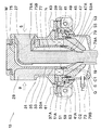
【図1】本発明の実施の形態に係る吐出装置の要部の構成を示す断面図である。
【図2】本発明の実施の形態に係る成形機の全体的構成を概略的に示した説明図である。
【符号の説明】
1 包あん機
5 内包材
9 外皮材
13 重合ノズル
15 内包材供給装置
17 外皮材供給装置
19 (棒状の)食品材料
31 上部ケーシング
33 内筒
35 外筒
37 軸受
41 リングギヤ
43 羽根
45 軸受
47 下部ケーシング
51 壁部
51A 内周
71 冷気
S 通路
M 空間
N 断熱空間[0001]
BACKGROUND OF THE INVENTION
The present invention relates to a joining and discharging method and apparatus that joins an inner packaging material as an inner food material and an outer skin material as an outer food material, and continuously discharges a rod-shaped food material, and more particularly, a wharf in a food molding machine The present invention relates to a food material joining and discharging method and apparatus for forming a continuous bar-shaped food material as a pre-stage of the step of spherically forming a bun in a molding process such as the above.
[0002]
[Prior art]
As a conventional method relating to the present invention, as shown in FIG. 1 of Japanese Examined Patent Publication No. 7-34703 (Conventional Example 1), a tube-shaped jacket is provided on the outer periphery of a supply member of an outer skin material, and a coolant or A manufacturing method is shown in which a cooling gas is flowed to cool the outer skin material near the position where the outer skin material is joined to the inner packaging material by the supply member.
In this manufacturing method, the outer skin material is temporarily cooled. However, since the outer skin material is cooled through the supply member, heat is accumulated in the supply member when the high temperature outer skin material is used, and the cooling efficiency is improved. There was a problem of reduction.
[0003]
In addition, the above-described conventional example 1 shows a manufacturing method in which a rod-shaped food material is cooled in a process before being discharged from the discharge device, but Japanese Patent Publication No. 7-40871 (conventional example 2) describes A manufacturing method is shown in which a rod-shaped food material made of a paste-like inner packaging material and a cheese shell material is encapsulated and cut by a shutter, and then the encapsulated food is cooled.
However, for example, in the manufacture of strawberry ice consisting of an ice cream envelope material and a fertilizer rind shell material, after forming the shell material fertilizer mash with a steaming machine, etc., the food is molded like a wrapping machine at a high temperature. In the case of supplying to the apparatus, in the manufacturing method of cooling the encapsulated food after encapsulating cutting as in Conventional Example 2, the ice cream is dissolved by the heat of the fertilizer and its properties are altered, There was a problem that the encapsulated food could not keep a spherical shape and became flat.
[0004]
[Problems to be solved by the invention]
An object of the present invention is to suppress deterioration of food materials due to a temperature difference between the food materials in a joining and discharging method and apparatus for joining a plurality of food materials and continuously discharging them as stick-shaped food materials. is there.
[0005]
[Means for Solving the Problems]
The present invention solves the above-described problems. In the method, for example, frozen confectionery is supplied as an inner food material from the inner food material supply device into the casing, and the outer food material is supplied from the outer food material supply device. The dough is supplied, the outer periphery of the inner food material and the outer food material are joined, and cold air is blown directly around the joined and discharged rod-shaped food material.
[0006]
Further, an inner food material supply device for supplying the inner food material into the casing and an outer food material supply device for supplying the outer food material into the casing are provided, and a passage for the inner food material is provided in the casing. An annular outer food material passage is provided around a partition wall around the inner food material passage, and the inner food material and the outer portion are disposed at a position where the inner food material passage and the outer food material passage are in contact with each other. The food material is joined, and cold air is blown directly onto the rod-shaped food material made of the joined inner food material and outer food material.
[0007]
The casing outlet is provided with a cover for holding cold air at intervals around the rod-shaped food material discharged from the outlet.
[0008]
DETAILED DESCRIPTION OF THE INVENTION
As shown conceptually in FIG. 2, the
[0009]
Below the
[0010]
In addition, since the said inner packaging
[0011]
Referring to FIG. 2, the
[0012]
A
[0013]
The shape of the rotor is not limited to a plate-like shape as shown in the present embodiment, but can be appropriately selected such as a round bar shape. Depending on the properties of the
In addition, the
[0014]
An
With such a structure, a heat insulating space N is formed between the
[0015]
The outer
[0016]
Further, outside the
Further, a
[0017]
The
[0018]
The superposed
[0019]
In the
[0020]
The
[0021]
The
[0022]
In the conventional polymerization nozzle, the ice cream of the
[0023]
In the present embodiment, the
For example, the outer material nozzle may be fixedly mounted without rotating. Further, without using the
[0024]
Furthermore, in the present embodiment, a space N is provided between the
[0025]
Further, in this embodiment, ice cream is used as the
[0026]
When a casing having a short flow path for the
[0027]
In addition to the above embodiment, this apparatus can also be used for producing Daifuku using straw as the
In this case, although the transformation of the koji due to the heat of the koji dough is not so much observed, by cooling the stick-shaped
[0028]
In the above-described embodiment, the case where the
[0029]
The koji dough cooled to about 10 ° C. has strong elasticity, and when the
In such a case, by supplying warm air to the space N and directly heating the skin material 9 (skin fabric), the stretch of the silk fabric is improved. It becomes possible to mold the covered food.
[0030]
【The invention's effect】
ADVANTAGE OF THE INVENTION According to this invention, in the joining discharge method and apparatus which join a some food material and discharge continuously as a rod-shaped food material, the quality change of the food material by the temperature difference between these food materials can be suppressed.
[Brief description of the drawings]
FIG. 1 is a cross-sectional view showing a configuration of a main part of a discharge device according to an embodiment of the present invention.
FIG. 2 is an explanatory view schematically showing an overall configuration of a molding machine according to an embodiment of the present invention.
[Explanation of symbols]
DESCRIPTION OF
Claims (5)
Priority Applications (1)
| Application Number | Priority Date | Filing Date | Title |
|---|---|---|---|
| JP2001132938A JP3640903B2 (en) | 2001-04-27 | 2001-04-27 | Method and apparatus for joining and discharging food materials |
Applications Claiming Priority (1)
| Application Number | Priority Date | Filing Date | Title |
|---|---|---|---|
| JP2001132938A JP3640903B2 (en) | 2001-04-27 | 2001-04-27 | Method and apparatus for joining and discharging food materials |
Publications (2)
| Publication Number | Publication Date |
|---|---|
| JP2002325538A JP2002325538A (en) | 2002-11-12 |
| JP3640903B2 true JP3640903B2 (en) | 2005-04-20 |
Family
ID=18980878
Family Applications (1)
| Application Number | Title | Priority Date | Filing Date |
|---|---|---|---|
| JP2001132938A Expired - Fee Related JP3640903B2 (en) | 2001-04-27 | 2001-04-27 | Method and apparatus for joining and discharging food materials |
Country Status (1)
| Country | Link |
|---|---|
| JP (1) | JP3640903B2 (en) |
Cited By (1)
| Publication number | Priority date | Publication date | Assignee | Title |
|---|---|---|---|---|
| CN111315242A (en) * | 2017-11-09 | 2020-06-19 | 雷恩自动机株式会社 | Food material discharging device |
Families Citing this family (6)
| Publication number | Priority date | Publication date | Assignee | Title |
|---|---|---|---|---|
| JP4287323B2 (en) * | 2004-04-22 | 2009-07-01 | 株式会社日本製鋼所 | Jerky manufacturing method and jerky manufacturing die |
| JP4814605B2 (en) * | 2005-10-07 | 2011-11-16 | レオン自動機株式会社 | Food dough discharging apparatus and method |
| JP2010136687A (en) * | 2008-12-12 | 2010-06-24 | Nissei Maryland Cup Kk | Nozzle for filling food material |
| US8926308B2 (en) | 2010-04-21 | 2015-01-06 | Intercontinental Great Brands Llc | Dough extruders and methods |
| JP6596619B2 (en) * | 2017-06-06 | 2019-10-30 | 株式会社コバード | Method and apparatus for producing sandwiched food |
| EP3884779A1 (en) * | 2020-03-27 | 2021-09-29 | Albert Handtmann Maschinenfabrik GmbH & Co. KG | Method and device for processing dough |
-
2001
- 2001-04-27 JP JP2001132938A patent/JP3640903B2/en not_active Expired - Fee Related
Cited By (2)
| Publication number | Priority date | Publication date | Assignee | Title |
|---|---|---|---|---|
| CN111315242A (en) * | 2017-11-09 | 2020-06-19 | 雷恩自动机株式会社 | Food material discharging device |
| CN111315242B (en) * | 2017-11-09 | 2021-12-17 | 雷恩自动机株式会社 | Food material discharge device, method of operating the same, and wrapped food manufacturing apparatus |
Also Published As
| Publication number | Publication date |
|---|---|
| JP2002325538A (en) | 2002-11-12 |
Similar Documents
| Publication | Publication Date | Title |
|---|---|---|
| RU2214101C2 (en) | Frozen aerated confectionery product with pictures, method and apparatus for producing the same | |
| JP3640903B2 (en) | Method and apparatus for joining and discharging food materials | |
| NO312051B1 (en) | Process, product, and apparatus for making frozen aerated products | |
| KR100923120B1 (en) | Manufacturing apparatus for a stick of rounded rice cake | |
| JPH03504198A (en) | Granulator and method of making frozen pellets | |
| JP2001505144A (en) | Equipment for homogenization, mixing and / or granulation of chemicals | |
| WO1997038844A1 (en) | Method and arrangement for cooling an extruded hollow product | |
| FR2572899A1 (en) | Method and installation for manufacturing a filled product | |
| US10159263B2 (en) | Apparatus and methods for making frozen banana food products | |
| NO156392B (en) | PROCEDURE AND APPARATUS FOR THE PREPARATION OF A HOLLYWOOD BAKING COVER, WHICH IS AT LEAST SUBJECTED ON THE INSIDE AND MAY BE FILLED AT LEAST PART. | |
| JPS6324B2 (en) | ||
| JP2006516015A (en) | Conveyor screw for use as a surface scraper in cooling and refrigeration units | |
| JP2011525801A (en) | Molding method of food by low temperature extrusion using predictive temperature control | |
| CN106262001A (en) | The secondary low temperature of fish pill surpasses processing method for quick-freezing and machining production line thereof | |
| JP3218042B2 (en) | Frozen food whose outer surface is covered with ice coating and method thereof | |
| JP3817335B2 (en) | Chocolate production method | |
| EA018468B1 (en) | Process and apparatus for manufacturing frozen aerated confections | |
| JPS59173073A (en) | Preparation of rolled kamaboko having rod-shaped core | |
| JP4009675B2 (en) | Twist food molding equipment | |
| KR100698967B1 (en) | Underground conduit forming apparatus | |
| JP3968727B2 (en) | Composite chocolate confectionery and manufacturing method thereof, composite chocolate confectionery manufacturing apparatus | |
| EP3280269B1 (en) | System and method for extruding confectionery products | |
| CN210646275U (en) | Rotary drum structure for flaker | |
| JP3693589B2 (en) | Method and apparatus for discharging food material | |
| KR0140926B1 (en) | Apparatus for making chocolate |
Legal Events
| Date | Code | Title | Description |
|---|---|---|---|
| A977 | Report on retrieval |
Free format text: JAPANESE INTERMEDIATE CODE: A971007 Effective date: 20040913 |
|
| TRDD | Decision of grant or rejection written | ||
| A01 | Written decision to grant a patent or to grant a registration (utility model) |
Free format text: JAPANESE INTERMEDIATE CODE: A01 Effective date: 20050118 |
|
| A61 | First payment of annual fees (during grant procedure) |
Free format text: JAPANESE INTERMEDIATE CODE: A61 Effective date: 20050119 |
|
| R150 | Certificate of patent or registration of utility model |
Free format text: JAPANESE INTERMEDIATE CODE: R150 |
|
| FPAY | Renewal fee payment (event date is renewal date of database) |
Free format text: PAYMENT UNTIL: 20110128 Year of fee payment: 6 |
|
| FPAY | Renewal fee payment (event date is renewal date of database) |
Free format text: PAYMENT UNTIL: 20110128 Year of fee payment: 6 |
|
| FPAY | Renewal fee payment (event date is renewal date of database) |
Free format text: PAYMENT UNTIL: 20110128 Year of fee payment: 6 |
|
| FPAY | Renewal fee payment (event date is renewal date of database) |
Free format text: PAYMENT UNTIL: 20120128 Year of fee payment: 7 |
|
| FPAY | Renewal fee payment (event date is renewal date of database) |
Free format text: PAYMENT UNTIL: 20120128 Year of fee payment: 7 |
|
| FPAY | Renewal fee payment (event date is renewal date of database) |
Free format text: PAYMENT UNTIL: 20130128 Year of fee payment: 8 |
|
| FPAY | Renewal fee payment (event date is renewal date of database) |
Free format text: PAYMENT UNTIL: 20130128 Year of fee payment: 8 |
|
| FPAY | Renewal fee payment (event date is renewal date of database) |
Free format text: PAYMENT UNTIL: 20130128 Year of fee payment: 8 |
|
| R250 | Receipt of annual fees |
Free format text: JAPANESE INTERMEDIATE CODE: R250 |
|
| R250 | Receipt of annual fees |
Free format text: JAPANESE INTERMEDIATE CODE: R250 |
|
| R250 | Receipt of annual fees |
Free format text: JAPANESE INTERMEDIATE CODE: R250 |
|
| LAPS | Cancellation because of no payment of annual fees |