JP3640496B2 - Repair method for plate heat exchanger - Google Patents
Repair method for plate heat exchanger Download PDFInfo
- Publication number
- JP3640496B2 JP3640496B2 JP05970197A JP5970197A JP3640496B2 JP 3640496 B2 JP3640496 B2 JP 3640496B2 JP 05970197 A JP05970197 A JP 05970197A JP 5970197 A JP5970197 A JP 5970197A JP 3640496 B2 JP3640496 B2 JP 3640496B2
- Authority
- JP
- Japan
- Prior art keywords
- heat transfer
- transfer plate
- nozzle
- pair
- welded
- Prior art date
- Legal status (The legal status is an assumption and is not a legal conclusion. Google has not performed a legal analysis and makes no representation as to the accuracy of the status listed.)
- Expired - Fee Related
Links
Images


Description
【0001】
【発明の属する技術分野】
本発明は、複数の伝熱板容器の内外に伝熱媒体を循環させて伝熱板の表裏を流れる流体間で熱交換を行うプレート式熱交換器の補修方法に関する。
【0002】
【従来の技術】
従来、たとえばプレート式熱交換器の製造方法は、図5(a)に示すように、プレス加工して、その表面に複数の凹部2の天面2aとノズル孔4が形成されるとともに、裏面に周縁部3と凹部2の開口面2bが形成された伝熱板1を製造し、ついで図5(b)に示すように、これら伝熱板1,1の裏面同志を重ね合わせ周縁部3,3を外側から溶接により接合して中空の伝熱板容器5を形成し、さらに図5(c)に示すように、これら複数の伝熱板容器5,5を積層してノズル孔4の縁部同志を溶接して組み立て、伝熱板容器群6を形成していた。
【0003】
また、伝熱板容器5に破孔が発生した場合、破孔箇所を特定した後、破孔のある伝熱板容器6全体をノズル筒4の縁部を切断して取り除き、上記と同様にして組み立てられた伝熱板容器(群)6を、ノズル孔4を溶接して補修していた。
【0004】
【発明が解決しようとする課題】
しかし、上記組立作業で伝熱板1の周縁部3の溶接は外周側から実施できるため容易であるが、ノズル口4の縁部の溶接は、その外周部で凹部2の底面2b同志が互いに接近しているため、ノズル口4の内側から行う必要がある。したがって、このノズル口4の縁部の溶接作業では、多く伝熱板容器6が積層されるほど溶接部が深くなり、作業性が悪くなって高度の溶接技術を必要とするという問題があった。
【0005】
本発明は、上記問題点を解決して、高度の技術を必要とせず、作業性のよいプレート式熱交換器の補修方法を提供することを目的とする。
【0008】
【課題を解決するための手段】
上記目的を達成するために本発明は、裏面側に周縁部と凹部の開口面とが形成されるとともに表面側に凹部の底面およびノズル口が形成された伝熱板と、一対の前記伝熱板の裏面同志を突き合わせ周縁部同志が接合された中空状の伝熱板容器と、これら複数の伝熱板容器のノズル口の縁部同志が接合されて積層された伝熱板容器群からなるプレート式熱交換器を補修するに際し、破損箇所を含む所定範囲の伝熱板容器群を、その両端のノズル口の縁部を切断して除去した後、この除去部分に臨む端面に新設伝熱板の表面を突き合わせてノズル口の縁部同志をノズル口の内側から溶接して連結し、ついで伝熱板の表面同志を突き合わせてノズル口の縁部同志をノズル口の内側から溶接して伝熱板対を組み立て、前記伝熱板対または、伝熱板対の表面同志を重ねて周縁部を溶接した伝熱板対容器群を前記除去部分に挿入して前記新設伝熱板の裏面に重ね合わせ、その周縁部同士を溶接し接合するものである。
【0009】
上記構成によれば、ノズル口の縁部を切断して破損箇所を含む伝熱板容器群を除去した後、切断部にノズル口を突き合わせ浅い位置で溶接して新設伝熱板を取り付け、さらに除去部分に伝熱板対または伝熱板対容器群を除去部に挿入して、伝熱板の周縁部を外周側から溶接して取り付けるので、ノズル筒の縁部の溶接部深さを浅くすることができ、最後に伝熱板の周縁部を溶接して組み立てるので、高度な溶接技術も不要となり、作業性を高めることができる。
【0010】
【発明の実施の形態】
ここで、本発明に係るプレート&シェル形熱交換器の製造方法および補修方法の実施の形態を図1〜図3に基づいて説明する。
【0011】
このプレート&シェル形熱交換器は、図3に示すように、第1熱媒液Aが流送されるシェル11内に、第2熱媒液Bが内部に流送される積層形伝熱板容器群12を内蔵したものである。前記シェル11は、円筒状の側壁21と底壁22と開閉可能な蓋体23とで円筒容器状に形成され、側壁21に熱媒入口24と熱媒出口25とが形成され、そして蓋体23に第2熱媒液Bの給排出用のノズル管14を介して伝熱板容器群12が配設されている。
【0012】
前記伝熱板容器群12は、図1(a),(b)に示すように、プレス加工により、素材プレートPが、周縁部32と複数の凹部33とノズル口34を有する伝熱板31が形成される。すなわち互いに平行な平面である表面と裏面のうち、裏面側に周縁部32と凹部33の開口面33aが形成されるとともに、表面側に凹部33の底面33bおよびノズル口34が形成されている。そしてこの一対の伝熱板31の裏面を重ね合わせて周縁部32,32を接合し伝熱板容器13が形成されている。この伝熱板容器13は、たとえば図1(a)に実線と波線で示すように、その凹部33,33を交差状になるように重ねられその開口部33aが点接触させて強度が向上されるとともに、凹部33により形成される中空部にノズル口34から第2熱媒液Bが流通するように構成される。また端部伝熱板31aを除く各伝熱板31には、第2熱媒液Bの流入口および排出口となるノズル口34がそれぞれ形成され、その縁部が凹部33の底面33bより少し突出されて隣接する伝熱板容器13のノズル口34の縁部と溶接により接合されている。また蓋体23側のノズル口34には、蓋体23を貫通するノズル管14が溶接により接合されている。
【0013】
次にこのプレート&シェル形熱交換器における伝熱板容器群12の製造方法を説明する。
1.図1(a)および(b)に示すように、まず素材プレートPからプレス加工により、周縁部32と凹部33とノズル口34を有する伝熱板31を成形する。
【0014】
2.図1(c)に示すように、一対の伝熱板31の表面を突き合わせてノズル口34の縁部を内側から溶接し伝熱板対15を形成する。この溶接作業は、ノズル口34の内側から内部を通して溶接することになるが、深さが小さいため高度な技術も不要で容易に行え、作業性がよい。
【0015】
3.図2(a)に示すように、伝熱板対15同士を積層して接合し伝熱板対容器16を形成する。すなわち各伝熱板対15の伝熱板31の裏面同志を重ね合わして周縁部32を外側から溶接により接合し、さらに伝熱板対15を追加して伝熱板対容器群16を形成する。
【0016】
4.図2(b)に示すように、伝熱板対容器群16の一端面に、ノズル口34の形成していない端部伝熱板31aをその裏面同志を重ね合わして周縁部32を外側から溶接により接合する。また他端側には、伝熱板31をその裏面同志を重ね合わして周縁部33を外側から溶接し接合した後、この伝熱板31のノズル口34にノズル管14を溶接し、さらにこのノズル管14を蓋体23の貫通孔に嵌合して溶接固定する。
【0017】
上記実施の形態によれば、最初にノズル口34の縁部を溶接して伝熱板対15を形成し、次いで複数の伝熱板対15の伝熱板31の裏面同志を重ねてその周縁部32を溶接することにより伝熱板対容器群16を組み立てるので、内部からの溶接を必要とするノズル口34の接合を浅い位置で行うことができ、したがって高度な溶接技術を必要とせず、作業性がよい。
【0018】
次に本発明に係る熱交換器用伝熱板群の補修方法の実施の形態を図3に基づいて説明する。なお、上記実施の形態と同一部材には同一符号を付して説明は省略する。
【0019】
伝熱板容器群12の一部に破損が生じて破孔した場合、
1.シェル11から伝熱板容器群12を外に取り出し、気密試験などにより破断部や破孔部を特定する。
【0020】
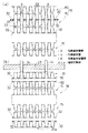
2.そして、図4(a)に示すように、破断部、破孔部が形成された少なくとも1個の伝熱板容器13からなる伝熱板容器群13Bを、ワイヤカットソーなどによりノズル口36の縁部を切断部Cで切断して取り外す。
【0021】
3.図4(b)に示すように、この切断部Cに新設伝熱板31bをノズル口34の縁部同士を溶接して接合する。この溶接作業も、ノズル口34内から内部を通して溶接するが、ノズル口34の深さが浅いために高度な技術も不要で容易に行え、作業性がよい。
【0022】
4.図4(b)に示すように、一対の伝熱板31の表面同志を突き合わせてノズル口34の縁部同士を溶接し伝熱板対15を形成する。この溶接作業も、ノズル口34から内部を通して溶接することになるが、深さが短いため、高度な技術も不要で容易に行え、作業性がよい。さらに削除した伝熱容器群(両端部の伝熱板31を除く)に対応して複数の伝熱板対15同志をその周縁部32を溶接して伝熱板対容器群16を形成するが、図4のように削除部分の伝熱板容器13が2個の場合には、この作業はない。
【0023】
5.図4(c)に示すように、伝熱板対15(または伝熱板対容器群)を新設伝熱板31aの間に配置して周縁部32を溶接により接合する。なお、削除部分の伝熱板容器13が1個の場合には、新設伝熱板31a同志を溶接して接合すればよい。
【0024】
上記実施の形態によれば、最初に切断部にノズル口34の縁部を溶接して新設伝熱板31bを接合し、次いで先にノズル筒36同士を接合した伝熱板対15(または伝熱板対容器群16)を配置して周縁部32を溶接し接合するので、内部からの溶接を必要とするノズル口34の溶接を浅い位置で行うことができ、したがって高度な溶接技術を必要とせず、補修を迅速に行うことができる。
【0026】
【発明の効果】
以上に述べたごとく本発明は、ノズル口の縁部を切断して破損箇所を含む伝熱板容器群を除去した後、切断部にノズル口を突き合わせ溶接して新設伝熱板を取り付け、さらに除去部分に伝熱板対または伝熱板対容器群を、伝熱板の周縁部を溶接して取り付けるので、ノズル筒の溶接部の深さを浅くすることができ、最後に伝熱板の周縁部を溶接して組み立てるので、高度な溶接技術も不要となり、作業性を高めることができる。
【図面の簡単な説明】
【図1】本発明に係る伝熱板群の製造方法の実施の形態を示し、(a)〜(c)はそれぞれ手順を示す説明図である。
【図2】同伝熱板群の製造方法の実施の形態を示し、(a),(b)はそれぞれ手順を示す説明図である。
【図3】同伝熱板群を内蔵したプレート&シェル形熱交換器の分解図である。
【図4】(a)〜(c)は同伝熱板群の補修方法を説明する分解図である。
【図5】(a)〜(c)は従来の伝熱板容器群の製造方法の説明図である。
【符号の説明】
11 シェル
12 伝熱板容器群
13 伝熱板容器
14 ノズル口
15 伝熱板対
16 伝熱板対容器群
31 伝熱板
31a 端部伝熱板
31b 端部伝熱板
32 周縁部
33 横部壁
33a 開口面
33b 底部
34 ノズル口[0001]
BACKGROUND OF THE INVENTION
The present invention relates to a repair method for a plate heat exchanger in which a heat transfer medium is circulated in and out of a plurality of heat transfer plate containers to exchange heat between fluids flowing on the front and back of the heat transfer plate.
[0002]
[Prior art]
Conventionally, for example, in a method for manufacturing a plate heat exchanger, as shown in FIG. 5 (a), the
[0003]
Further, when a hole is generated in the heat
[0004]
[Problems to be solved by the invention]
However, the
[0005]
An object of the present invention is to provide a method for repairing a plate heat exchanger that solves the above-described problems and does not require a high level of technology and has good workability.
[0008]
[Means for Solving the Problems]
To achieve the above object, the present invention provides a heat transfer plate in which a peripheral edge and an opening surface of a recess are formed on the back surface side, and a bottom surface of the recess and a nozzle port are formed on the front surface side, and a pair of the heat transfer plates It consists of a hollow heat transfer plate container in which the back sides of the plate are abutted and the peripheral edge members are bonded, and a group of heat transfer plate containers in which the edge portions of the nozzle ports of the plurality of heat transfer plate containers are bonded and stacked. When repairing a plate heat exchanger, the heat transfer plate container group in a specified range including the damaged part is removed by cutting the edges of the nozzle openings at both ends, and then newly installed on the end face facing the removed part. The plate surfaces are butted together and the nozzle edges are welded from the inside of the nozzle port, and then the heat transfer plate surfaces are butted together and the nozzle port edges are welded from the inside of the nozzle port. Assembling the heat plate pair, the heat transfer plate pair or the heat transfer plate pair The heat transfer plate pairs container group with a welded peripheral portion overlapping a face each other and inserted into the removed portion overlaid on the back surface of the newly heat transfer plate, it is to weld joining the peripheral edge portions.
[0009]
According to the above configuration, after cutting the edge portion of the nozzle port and removing the heat transfer plate container group including the damaged portion, the nozzle port is butted against the cutting portion and welded at a shallow position, and the newly installed heat transfer plate is attached. The heat transfer plate pair or heat transfer plate pair container group is inserted into the removal part at the removal part, and the peripheral part of the heat transfer plate is welded and attached from the outer peripheral side, so the welded part depth at the edge of the nozzle cylinder is shallow. Finally, since the peripheral edge portion of the heat transfer plate is assembled by welding, an advanced welding technique is not required and workability can be improved.
[0010]
DETAILED DESCRIPTION OF THE INVENTION
Here, an embodiment of a method for manufacturing and repairing a plate-and-shell heat exchanger according to the present invention will be described with reference to FIGS.
[0011]
As shown in FIG. 3, this plate & shell type heat exchanger has a laminated heat transfer in which the second heat transfer fluid B is flowed into the
[0012]
As shown in FIGS. 1A and 1B, the heat transfer
[0013]
Next, the manufacturing method of the heat-transfer
1. As shown in FIGS. 1A and 1B, first, a
[0014]
2. As shown in FIG. 1C, the surfaces of the pair of
[0015]
3. As shown in FIG. 2A, the heat
[0016]
4). As shown in FIG. 2 (b), the end
[0017]
According to the above embodiment, the edge of the
[0018]
Next, an embodiment of a method for repairing a heat exchanger plate group for a heat exchanger according to the present invention will be described with reference to FIG. In addition, the same code | symbol is attached | subjected to the same member as the said embodiment, and description is abbreviate | omitted.
[0019]
When a part of the heat transfer
1. The heat transfer
[0020]
2. 4A, the heat transfer
[0021]
3. As shown in FIG. 4B, the newly installed
[0022]
4). As shown in FIG. 4 (b), the surfaces of the pair of
[0023]
5. As shown in FIG.4 (c), the heat exchanger plate pair 15 (or heat exchanger plate pair container group) is arrange | positioned between the newly installed
[0024]
According to the above embodiment, the edge of the
[0026]
【The invention's effect】
As described above, the present invention cuts the edge of the nozzle port and removes the heat transfer plate container group including the damaged portion, and then attaches the newly installed heat transfer plate by butt welding the nozzle port to the cut portion. Since the heat transfer plate pair or heat transfer plate pair container group is attached to the removed portion by welding the peripheral edge of the heat transfer plate, the depth of the welded portion of the nozzle tube can be reduced, and finally the heat transfer plate Since the peripheral portion is welded and assembled, an advanced welding technique is not required, and workability can be improved.
[Brief description of the drawings]
FIG. 1 shows an embodiment of a method for producing a heat transfer plate group according to the present invention, and (a) to (c) are explanatory views showing procedures.
FIG. 2 shows an embodiment of a method for producing the heat transfer plate group, and (a) and (b) are explanatory views showing procedures.
FIG. 3 is an exploded view of a plate and shell type heat exchanger incorporating the heat transfer plate group.
4A to 4C are exploded views for explaining a repair method for the heat transfer plate group. FIG.
5A to 5C are explanatory views of a conventional method for manufacturing a heat transfer plate container group.
[Explanation of symbols]
11
Claims (1)
破損箇所を含む所定範囲の伝熱板容器群を、その両端のノズル口の縁部を切断して除去した後、After removing the heat transfer plate container group in a predetermined range including the damaged portion by cutting the edges of the nozzle ports at both ends,
この除去部分に臨む端面に新設伝熱板の表面を突き合わせてノズル口の縁部同志をノズル口の内側から溶接して連結し、The surface of the newly installed heat transfer plate is abutted against the end face facing this removed part, and the edges of the nozzle opening are welded from the inside of the nozzle opening and connected,
ついで伝熱板の表面同志を突き合わせてノズル口の縁部同志をノズル口の内側から溶接して伝熱板対を組み立て、Next, the surfaces of the heat transfer plates are matched, and the edges of the nozzle port are welded from the inside of the nozzle port to assemble the heat transfer plate pair.
前記伝熱板対または、伝熱板対の表面同志を重ねて周縁部を溶接した伝熱板対容器群を前記除去部分に挿入して前記新設伝熱板の裏面に重ね合わせ、その周縁部同士を溶接し接合するThe heat transfer plate pair or a heat transfer plate pair container group in which the surfaces of the heat transfer plate pair are overlapped and the peripheral portion is welded is inserted into the removal portion and overlapped on the back surface of the newly installed heat transfer plate, and the peripheral portion Weld and join each other
ことを特徴とするプレート式熱交換器の補修方法。A method for repairing a plate heat exchanger.
Priority Applications (1)
| Application Number | Priority Date | Filing Date | Title |
|---|---|---|---|
| JP05970197A JP3640496B2 (en) | 1997-03-14 | 1997-03-14 | Repair method for plate heat exchanger |
Applications Claiming Priority (1)
| Application Number | Priority Date | Filing Date | Title |
|---|---|---|---|
| JP05970197A JP3640496B2 (en) | 1997-03-14 | 1997-03-14 | Repair method for plate heat exchanger |
Publications (2)
| Publication Number | Publication Date |
|---|---|
| JPH10253281A JPH10253281A (en) | 1998-09-25 |
| JP3640496B2 true JP3640496B2 (en) | 2005-04-20 |
Family
ID=13120791
Family Applications (1)
| Application Number | Title | Priority Date | Filing Date |
|---|---|---|---|
| JP05970197A Expired - Fee Related JP3640496B2 (en) | 1997-03-14 | 1997-03-14 | Repair method for plate heat exchanger |
Country Status (1)
| Country | Link |
|---|---|
| JP (1) | JP3640496B2 (en) |
Families Citing this family (1)
| Publication number | Priority date | Publication date | Assignee | Title |
|---|---|---|---|---|
| SE534915C2 (en) * | 2010-06-18 | 2012-02-14 | Alfa Laval Corp Ab | Plate heat exchanger and method for manufacturing a plate heat exchanger |
-
1997
- 1997-03-14 JP JP05970197A patent/JP3640496B2/en not_active Expired - Fee Related
Also Published As
| Publication number | Publication date |
|---|---|
| JPH10253281A (en) | 1998-09-25 |
Similar Documents
| Publication | Publication Date | Title |
|---|---|---|
| US2961222A (en) | Heat exchanger | |
| EP2583045B1 (en) | Plate heat exchanger and method of producing a plate heat exchanger | |
| JPH07227631A (en) | Guide tube for heat exchanging in laminated layer type heat exchanger and its manufacture | |
| US10598440B2 (en) | Method of manufacturing heat exchanger | |
| JPH06506054A (en) | Welded plate-shaped fin type heat exchanger and method for manufacturing plate-shaped fins for heat exchanger | |
| TWI787474B (en) | Honeycomb panel, manufacturing method thereof, and shell | |
| FI70471C (en) | PLATTVAERMEVAEXLARE | |
| US20100175861A1 (en) | Laser-welded heat exchanger tube assembly | |
| JP2002137054A (en) | Heat exchanger and its production method | |
| JP3640496B2 (en) | Repair method for plate heat exchanger | |
| JP3590634B2 (en) | Plate heat exchanger | |
| EP0706634B1 (en) | Welded plate heat exchanger and method for welding heat transfer plates to a plate heat exchanger | |
| JP2003194490A (en) | Heat exchanger unit | |
| JP2002107090A (en) | Plate-type heat exchanger and producing method | |
| EP0805330B1 (en) | Heat exchanger enabling leak test of chambers in tank separated by single partition | |
| JPH0429257Y2 (en) | ||
| JP4471423B2 (en) | Plate heat exchanger | |
| JPH0989477A (en) | Manufacture of heat exchanger | |
| JP3316082B2 (en) | Heat exchanger header tank | |
| JP4409723B2 (en) | High pressure heat exchanger | |
| JPH05118774A (en) | Laminated heat exchanger | |
| JPH063076A (en) | Manufacture of laminated heat exchanger | |
| JP2004270972A (en) | Lamination type heat exchanger and its manufacturing method | |
| JPH01203892A (en) | Plate type heat exchanger | |
| JP3661955B2 (en) | Heat exchanger for liquid heating and manufacturing method thereof |
Legal Events
| Date | Code | Title | Description |
|---|---|---|---|
| A131 | Notification of reasons for refusal |
Free format text: JAPANESE INTERMEDIATE CODE: A131 Effective date: 20040928 |
|
| A521 | Written amendment |
Free format text: JAPANESE INTERMEDIATE CODE: A523 Effective date: 20041126 |
|
| TRDD | Decision of grant or rejection written | ||
| A01 | Written decision to grant a patent or to grant a registration (utility model) |
Free format text: JAPANESE INTERMEDIATE CODE: A01 Effective date: 20041221 |
|
| A61 | First payment of annual fees (during grant procedure) |
Free format text: JAPANESE INTERMEDIATE CODE: A61 Effective date: 20050118 |
|
| FPAY | Renewal fee payment (event date is renewal date of database) |
Free format text: PAYMENT UNTIL: 20090128 Year of fee payment: 4 |
|
| FPAY | Renewal fee payment (event date is renewal date of database) |
Free format text: PAYMENT UNTIL: 20090128 Year of fee payment: 4 |
|
| FPAY | Renewal fee payment (event date is renewal date of database) |
Free format text: PAYMENT UNTIL: 20100128 Year of fee payment: 5 |
|
| FPAY | Renewal fee payment (event date is renewal date of database) |
Free format text: PAYMENT UNTIL: 20110128 Year of fee payment: 6 |
|
| LAPS | Cancellation because of no payment of annual fees |