JP3637700B2 - Clutch cable mounting structure - Google Patents
Clutch cable mounting structure Download PDFInfo
- Publication number
- JP3637700B2 JP3637700B2 JP27883796A JP27883796A JP3637700B2 JP 3637700 B2 JP3637700 B2 JP 3637700B2 JP 27883796 A JP27883796 A JP 27883796A JP 27883796 A JP27883796 A JP 27883796A JP 3637700 B2 JP3637700 B2 JP 3637700B2
- Authority
- JP
- Japan
- Prior art keywords
- clutch
- stiffener
- clutch cable
- cable
- mounting structure
- Prior art date
- Legal status (The legal status is an assumption and is not a legal conclusion. Google has not performed a legal analysis and makes no representation as to the accuracy of the status listed.)
- Expired - Fee Related
Links
Images


Landscapes
- Arrangement And Mounting Of Devices That Control Transmission Of Motive Force (AREA)
- Flexible Shafts (AREA)
- Mechanical Operated Clutches (AREA)
Description
【0001】
【発明の属する技術分野】
この発明はクラッチケーブル取付構造に係り、特にスティフナにブラケット機能を付加し、クラッチケーブル支持用のブラケットを不要としてスペースの有効利用を図り、クラッチケーブルの配索を簡易化し得るとともに、部品点数を削減し得るクラッチケーブル取付構造に関する。
【0002】
【従来の技術】
クラッチケーブルは、クラッチペダル等のクラッチ操作手段と手動変速機用クラッチ間に配設され、クラッチ操作手段の断続操作によってクラッチ内のレリーズフォークを起動し、クラッチを断続させている。
【0003】
また、エンジンには、シリンダブロックと手動変速機とを保持するためにスティフナが設けられている。
【0004】
前記クラッチケーブル取付構造としては、実開平6−40465号公報に開示されるものがある。この公報に開示される摩擦クラッチの防水構造は、クラッチハウジングの上部に形成された開孔から挿入されるクラッチレリーズレバーを有する摩擦クラッチの防水構造において、クラッチレリーズレバーのクラッチハウジング外側部分に、クラッチハウジング外表面との間に隙間を形成しつつ開孔を遮蔽し得るプレートを装着し、構造を簡略し、取り付け作業性を向上させるとともに、十分な防水性及び放熱性を確保している。
【0005】
【発明が解決しようとする課題】
ところで、従来のクラッチケーブル取付構造においては、四輪駆動車の手動変速機用のクラッチケーブルを支持する際に、クラッチケーブル支持用のブラケットを別途設け、このブラケットをエンジン側に固定ボルトによって固定したり、エンジンマウントに溶接していた。
【0006】
この結果、固定ボルトによるブラケットの締結等によって組付工数が多く、組付性が悪く、実用上不利であるという不都合がある。
【0007】
また、ブラケットを溶接にてエンジンマウントに固着する際には、溶接作業によってコストが大となり、経済的に不利であるという不都合がある。
【0008】
更に、クラッチケーブルを配索する際には、ブラケットを使用していることにより、配索スペースが小となり、クラッチケーブルのレイアウトが困難となるという不都合がある。
【0009】
【課題を解決するための手段】
そこで、この発明は、上述不都合を除去するために、手動変速機用クラッチに連絡されこのクラッチを断続させるクラッチケーブル取付構造において、エンジンのシリンダブロックと手動変速機とを保持するスティフナを設け、このスティフナは前記クラッチのクラッチハウジングプレートに対して面接触する基部とこの基部から前記シリンダブロック側方向である垂直方向に延びる腕部からなり、前記基部に略円形状の座面を設けるとともに座面中央部位には前記クラッチケーブルを支持する支持孔部を設け、該支持孔部を介して前記腕部に沿わせて前記クラッチケーブルを取り付けたことを特徴とする。
【0010】
【発明の実施の形態】
上述の如く発明したことにより、クラッチの遊び調整を行う際には、アウタを回動動作させてスティフナの支持孔部を貫通するクラッチケーブルの長さを調節し、クラッチの遊び調整を行い、スティフナにブラケット機能を付加し、スペースの有効利用を図り、クラッチケーブルの配索を簡易化するとともに、クラッチケーブル支持用のブラケットを不要とし、部品点数を削減している。
【0011】
【実施例】
以下図面に基づいてこの発明の実施例を詳細に説明する。
【0012】
図1〜図11はこの発明の実施例を示すものである。図5及び図8において、2はエンジン、4はシリンダブロック、6は手動変速機である。
【0013】
前記エンジン2のシリンダブロック4に、スティフナ8によって手動変速機6を保持して設ける。
【0014】
つまり、図5及び図8に示す如く、手動変速機6はクラッチ10を有しており、このクラッチ10と前記シリンダブロック4間にクラッチハウジングプレート12を介し、クラッチ10と前記シリンダブロック4とを前記スティフナ8によって固定するものである。
【0015】
前記手動変速機6用のクラッチ10には、このクラッチ10内の図示しないレリーズフォークを起動してクラッチ10の断続を行うべくクラッチケーブル14を連絡して設ける。
【0016】
そして、前記スティフナ8に略円形状の座面16を設けるとともに、座面16の中央部位に前記クラッチケーブル14を支持する支持孔部18を設ける構成とする。
【0017】
詳述すれば、前記スティフナ8は、図5、図8、図10及び図11に夫々示す如く、前記クラッチ10のクラッチハウジングプレート12に対して面接触する基部20と、この基部20から前記エンジン2のシリンダブロック4側方向である垂直方向に延びる腕部22とからなり、前記座面16を基部20に設けるものである。
【0018】
また、前記支持孔部18は、図1及び図2に示す如く、クラッチケーブル14の外径よりも大なる内径を有するように形成する。そして、図3に示す如く、前記支持孔部18を介して前記腕部22に沿わせて前記クラッチケーブル14を取り付ける。
【0019】
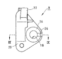
前記スティフナ8は、座面16の中央部位に設けた支持孔部18にてクラッチケーブル14を支持するとともに、クラッチ10の遊び調整を行うアウタ24の回り止めを行う切欠き部26を有している。
【0020】
クラッチ10の遊び調整は、図2及び図4に示す如く、アウタ24と、このアウタ24内に形成した螺刻部28に螺合し且つ両端にクラッチケーブル14が連絡する雌ネジ部材30とによって行われる。
【0021】
また、前記切欠き部26を、図1に示す如く、スティフナ8の支持孔部18と外周部位とを連絡すべく形成し、このとき、切欠き部26の深さを、図9及び図10に示す如く、スティフナ8の基部20の厚みの略半分とする。
【0022】
そして、前記スティフナ8の支持孔部18にクラッチケーブル14を貫通支持させる際には、スティフナ8の基部20とアウタ24間に回り止め部材32を介設する。
【0023】
この回り止め部材32は、前記支持孔部18に嵌入され且つ雌ネジ部材30を挿通させる筒状部32aと、筒状部32aの端部に形成した一部がアウタ24よりも外側部位に突出する変形フランジ部32bと、この変形フランジ部32bの突出部位に設けた係合ピン32cとからなる。
【0024】
更に、前記アウタ24の外周部位に、例えば6個の円弧状凹部24aを円周等間隔に形成し、アウタ24の回動動作にて雌ネジ部材30を進退動作させてクラッチケーブル14の長さを調節し、前記クラッチ10の遊び調整を行った後に、アウタ24の外周部位の円弧状凹部24aに回り止め部材32の係合ピン32cを係合させるとともに、係合ピン32cを前記スティフナ8の切欠き部26にも係合させ、アウタ24の回り止めを行う構成とする。
【0025】
次に作用について説明する。
【0026】
前記クラッチ10の遊び調整を行う際には、アウタ24を回動動作させて雌ネジ部材30を進退動作させ、この雌ネジ部材30を進退動作よってクラッチケーブル14の長さを調節し、前記クラッチ10の遊び調整を行う。
【0027】
そして、前記クラッチ10の遊び調整を行った後には、アウタ24の外周部位の円弧状凹部24aに回り止め部材32の係合ピン32cを係合させるとともに、係合ピン32cを前記スティフナ8の切欠き部26にも係合させ、アウタ24の回り止めを行う。
【0028】
これにより、前記スティフナ8にブラケット機能を付加することができ、従来のクラッチケーブル支持用のブラケットが不要となってスペースの有効利用が図れ、クラッチケーブル14の配索を簡易化し得て、実用上有利である。
【0029】
また、クラッチケーブル支持用のブラケットが不要となることにより、部品点数を削減し得て、コストダウンを果たし得るとともに、アウタ24や回り止め部材32の取付性を向上し得る。
【0030】
更に、前記スティフナ8が、座面16の中央部位に設けた支持孔部18にてクラッチケーブル14を支持するとともに、クラッチ10の遊び調整を行うアウタ24の回り止めを行う切欠き部26を有していることにより、スティフナ8の切欠き部26によってアウタ24の回り止めを確実に行うことができ、クラッチ10の遊び調整を確実に果たし得るものである。
【0031】
【発明の効果】
以上詳細に説明した如くこの発明によれば、手動変速機用クラッチに連絡されこのクラッチを断続させるクラッチケーブル取付構造において、エンジンのシリンダブロックと手動変速機とを保持するスティフナを設け、このスティフナはクラッチのクラッチハウジングプレートに対して面接触する基部とこの基部からシリンダブロック側方向である垂直方向に延びる腕部からなり、基部に略円形状の座面を設けるとともに座面中央部位にはクラッチケーブルを支持する支持孔部を設け、支持孔部を介して腕部に沿わせてクラッチケーブルを取り付けたので、前記スティフナにブラケット機能を付加することができ、スペースの有効利用が図れ、クラッチケーブルの配索を簡易化し得て、実用上有利である。また、クラッチケーブル支持用のブラケットが不要となることにより、部品点数を削減し得て、コストダウンを果たし得るとともに、アウタ等の取付性を向上し得る。更に、前記スティフナが、座面の中央部位に設けた支持孔部にてクラッチケーブルを支持するとともに、クラッチの遊び調整を行うアウタの回り止めを行う切欠き部を有していれば、スティフナの切欠き部によってアウタの回り止めを確実に行うことができ、クラッチの遊び調整を確実に果たし得る。
【図面の簡単な説明】
【図1】 この発明の実施例を示すスティフナの基部部分の要部拡大図である。
【図2】 クラッチケーブル装着時のスティフナの基部部分の要部拡大図である。
【図3】 スティフナ取付時の拡大図である。
【図4】 支持孔部に係合されるアウタ部分の要部拡大断面図である。
【図5】 手動変速機とクラッチ部分の概略図である。
【図6】 クラッチ部分の正面図である。
【図7】 図6の矢視VII部分の概略図である。
【図8】 エンジンのシリンダブロックと手動変速機部分の概略図である。
【図9】 図1のIX−IX線による断面図である。
【図10】 スティフナの平面図である。
【図11】 スティフナの正面図である。
【符号の説明】
2 エンジン
4 シリンダブロック
6 手動変速機
8 スティフナ
10 クラッチ
14 クラッチケーブル
16 座面
18 支持孔部
20 基部
22 腕部
24 アウタ
24a 円弧状凹部
26 切欠き部
28 螺刻部
30 雌ネジ部材
32 回り止め部材
32a 筒状部
32b 変形フランジ部
32c 係合ピン[0001]
BACKGROUND OF THE INVENTION
The present invention relates to a clutch cable mounting structure, and in particular, a bracket function is added to a stiffener to eliminate the need for a bracket for supporting the clutch cable, to effectively use the space, to simplify the routing of the clutch cable, and to reduce the number of parts. The present invention relates to a possible clutch cable mounting structure.
[0002]
[Prior art]
The clutch cable is disposed between a clutch operating means such as a clutch pedal and a manual transmission clutch, and activates a release fork in the clutch by the on / off operation of the clutch operating means to engage / disengage the clutch.
[0003]
The engine is also provided with a stiffener for holding the cylinder block and the manual transmission.
[0004]
As the clutch cable mounting structure, there is one disclosed in Japanese Utility Model Publication No. 6-40465. The waterproof structure of a friction clutch disclosed in this publication is a friction clutch waterproof structure having a clutch release lever inserted from an opening formed in an upper portion of the clutch housing. A plate capable of shielding the opening while forming a gap with the outer surface of the housing is mounted, the structure is simplified, the mounting workability is improved, and sufficient waterproofness and heat dissipation are ensured.
[0005]
[Problems to be solved by the invention]
By the way, in the conventional clutch cable mounting structure, when supporting a clutch cable for a manual transmission of a four-wheel drive vehicle, a bracket for supporting the clutch cable is separately provided, and this bracket is fixed to the engine side with a fixing bolt. Or welded to the engine mount.
[0006]
As a result, there are inconveniences that the number of assembling steps is large due to the fastening of the bracket with the fixing bolts, the assembling property is poor, and it is disadvantageous in practice.
[0007]
Further, when the bracket is fixed to the engine mount by welding, there is an inconvenience that the cost is high due to the welding operation, which is economically disadvantageous.
[0008]
Further, when the clutch cable is routed, the use of the bracket has a disadvantage that the routing space is reduced and the layout of the clutch cable becomes difficult.
[0009]
[Means for Solving the Problems]
Accordingly, in order to eliminate the above-described disadvantages, the present invention provides a stiffener for holding the engine cylinder block and the manual transmission in a clutch cable mounting structure that is connected to the manual transmission clutch and connects and disconnects the clutch. The stiffener includes a base portion that is in surface contact with the clutch housing plate of the clutch and an arm portion that extends from the base portion in a vertical direction that is the cylinder block side direction. A support hole portion for supporting the clutch cable is provided in the portion, and the clutch cable is attached along the arm portion through the support hole portion.
[0010]
DETAILED DESCRIPTION OF THE INVENTION
By inventing the clutch as described above, when adjusting the play of the clutch, the outer is rotated to adjust the length of the clutch cable passing through the support hole portion of the stiffener to adjust the play of the clutch. A bracket function has been added to the space for effective use of space, simplifying the cable routing, and eliminating the bracket for supporting the clutch cable, reducing the number of parts.
[0011]
【Example】
Embodiments of the present invention will be described below in detail with reference to the drawings.
[0012]
1 to 11 show an embodiment of the present invention. 5 and 8, 2 is an engine, 4 is a cylinder block, and 6 is a manual transmission.
[0013]
A
[0014]
That is, as shown in FIGS. 5 and 8, the
[0015]
A
[0016]
The
[0017]
More specifically, as shown in FIGS. 5, 8, 10, and 11, the
[0018]
Further, as shown in FIGS. 1 and 2, the
[0019]
The
[0020]
As shown in FIGS. 2 and 4, the play adjustment of the
[0021]
Further, as shown in FIG. 1, the
[0022]
When the
[0023]
The
[0024]
Further, for example, six arc-shaped
[0025]
Next, the operation will be described.
[0026]
When the play adjustment of the clutch 10 is performed, the outer 24 is rotated to move the
[0027]
After adjusting the play of the clutch 10, the
[0028]
As a result, a bracket function can be added to the
[0029]
Further, since the bracket for supporting the clutch cable is not required, the number of parts can be reduced, the cost can be reduced, and the attachment property of the outer 24 and the
[0030]
Further, the
[0031]
【The invention's effect】
As described above in detail, according to the present invention, in the clutch cable mounting structure that is connected to the manual transmission clutch and connects and disconnects the clutch, a stiffener that holds the cylinder block of the engine and the manual transmission is provided. It consists of a base part in surface contact with the clutch housing plate of the clutch and an arm part extending in the vertical direction from the base part to the cylinder block side. Since a support cable is provided along the arm part through the support hole, a bracket function can be added to the stiffener, space can be used effectively, and the clutch cable The routing can be simplified, which is practically advantageous. Further, since the bracket for supporting the clutch cable is not necessary, the number of parts can be reduced, the cost can be reduced, and the attachment property of the outer and the like can be improved. Further, if the stiffener has a notch portion for supporting the clutch cable in the support hole portion provided in the central portion of the seating surface and preventing the outer rotation for adjusting the play of the clutch, The outer rotation of the outer can be reliably prevented by the notch, and the play adjustment of the clutch can be surely achieved.
[Brief description of the drawings]
FIG. 1 is an enlarged view of a main part of a base portion of a stiffener showing an embodiment of the present invention.
FIG. 2 is an enlarged view of a main part of a base portion of a stiffener when a clutch cable is attached.
FIG. 3 is an enlarged view when the stiffener is attached.
FIG. 4 is an enlarged cross-sectional view of a main part of an outer portion engaged with a support hole portion.
FIG. 5 is a schematic view of a manual transmission and a clutch portion.
FIG. 6 is a front view of a clutch portion.
FIG. 7 is a schematic view of a portion VII in FIG.
FIG. 8 is a schematic view of a cylinder block and a manual transmission portion of the engine.
9 is a cross-sectional view taken along line IX-IX in FIG.
FIG. 10 is a plan view of a stiffener.
FIG. 11 is a front view of a stiffener.
[Explanation of symbols]
DESCRIPTION OF
Claims (2)
Priority Applications (1)
| Application Number | Priority Date | Filing Date | Title |
|---|---|---|---|
| JP27883796A JP3637700B2 (en) | 1996-09-30 | 1996-09-30 | Clutch cable mounting structure |
Applications Claiming Priority (1)
| Application Number | Priority Date | Filing Date | Title |
|---|---|---|---|
| JP27883796A JP3637700B2 (en) | 1996-09-30 | 1996-09-30 | Clutch cable mounting structure |
Publications (2)
| Publication Number | Publication Date |
|---|---|
| JPH10103379A JPH10103379A (en) | 1998-04-21 |
| JP3637700B2 true JP3637700B2 (en) | 2005-04-13 |
Family
ID=17602850
Family Applications (1)
| Application Number | Title | Priority Date | Filing Date |
|---|---|---|---|
| JP27883796A Expired - Fee Related JP3637700B2 (en) | 1996-09-30 | 1996-09-30 | Clutch cable mounting structure |
Country Status (1)
| Country | Link |
|---|---|
| JP (1) | JP3637700B2 (en) |
Families Citing this family (2)
| Publication number | Priority date | Publication date | Assignee | Title |
|---|---|---|---|---|
| US9057400B2 (en) * | 2007-12-19 | 2015-06-16 | Kongsberg Automotive Ab | Connecting device for transmission cable in vehicle |
| JP2019015192A (en) * | 2017-07-04 | 2019-01-31 | 日産自動車株式会社 | Power plant |
-
1996
- 1996-09-30 JP JP27883796A patent/JP3637700B2/en not_active Expired - Fee Related
Also Published As
| Publication number | Publication date |
|---|---|
| JPH10103379A (en) | 1998-04-21 |
Similar Documents
| Publication | Publication Date | Title |
|---|---|---|
| JP2708801B2 (en) | Cowling disengagement device for outboard motor | |
| JP3637700B2 (en) | Clutch cable mounting structure | |
| KR0132256B1 (en) | Til lamp of a car | |
| CA2280672C (en) | Axle housing assembly | |
| JP2003154966A (en) | Car body front part structure | |
| JP2543341Y2 (en) | Motor tank fuel tank support structure | |
| JP3462583B2 (en) | Work vehicle battery support structure | |
| JP3228019B2 (en) | Radiator mounting structure | |
| JP4055392B2 (en) | Tractor | |
| JP3896948B2 (en) | Power plant mounting device | |
| JP2524008Y2 (en) | Mounting device for internal combustion engine for vehicles | |
| JPH0448992Y2 (en) | ||
| JP2002362457A (en) | Rear fender fitting structure of motorcycle | |
| KR200142166Y1 (en) | Fixing structure of bracket for shift lever | |
| JP2013244774A (en) | Straddle type vehicle | |
| JPS6116235Y2 (en) | ||
| JP3051379U (en) | Bicycle chain case fixture | |
| JPH0638071Y2 (en) | Forklift hose guide | |
| JPS6039492Y2 (en) | starter | |
| JP2777580B2 (en) | Motorcycle fuel tank mounting device | |
| JPH10329559A (en) | Propeller shaft guard | |
| JP3277821B2 (en) | Release fork mounting structure for release fork | |
| JPH0247107Y2 (en) | ||
| JPH07317561A (en) | Idle gear supporting device of engine | |
| JP3745137B2 (en) | Seat hinge mechanism |
Legal Events
| Date | Code | Title | Description |
|---|---|---|---|
| A131 | Notification of reasons for refusal |
Free format text: JAPANESE INTERMEDIATE CODE: A131 Effective date: 20041005 |
|
| A521 | Written amendment |
Free format text: JAPANESE INTERMEDIATE CODE: A523 Effective date: 20041019 |
|
| TRDD | Decision of grant or rejection written | ||
| A01 | Written decision to grant a patent or to grant a registration (utility model) |
Free format text: JAPANESE INTERMEDIATE CODE: A01 Effective date: 20041221 |
|
| A61 | First payment of annual fees (during grant procedure) |
Free format text: JAPANESE INTERMEDIATE CODE: A61 Effective date: 20050103 |
|
| S531 | Written request for registration of change of domicile |
Free format text: JAPANESE INTERMEDIATE CODE: R313532 |
|
| R350 | Written notification of registration of transfer |
Free format text: JAPANESE INTERMEDIATE CODE: R350 |
|
| FPAY | Renewal fee payment (event date is renewal date of database) |
Free format text: PAYMENT UNTIL: 20090121 Year of fee payment: 4 |
|
| FPAY | Renewal fee payment (event date is renewal date of database) |
Free format text: PAYMENT UNTIL: 20100121 Year of fee payment: 5 |
|
| FPAY | Renewal fee payment (event date is renewal date of database) |
Free format text: PAYMENT UNTIL: 20110121 Year of fee payment: 6 |
|
| FPAY | Renewal fee payment (event date is renewal date of database) |
Free format text: PAYMENT UNTIL: 20110121 Year of fee payment: 6 |
|
| FPAY | Renewal fee payment (event date is renewal date of database) |
Free format text: PAYMENT UNTIL: 20120121 Year of fee payment: 7 |
|
| FPAY | Renewal fee payment (event date is renewal date of database) |
Free format text: PAYMENT UNTIL: 20130121 Year of fee payment: 8 |
|
| FPAY | Renewal fee payment (event date is renewal date of database) |
Free format text: PAYMENT UNTIL: 20130121 Year of fee payment: 8 |
|
| FPAY | Renewal fee payment (event date is renewal date of database) |
Free format text: PAYMENT UNTIL: 20140121 Year of fee payment: 9 |
|
| LAPS | Cancellation because of no payment of annual fees |