JP3631400B2 - Scaffolding frame connector - Google Patents
Scaffolding frame connector Download PDFInfo
- Publication number
- JP3631400B2 JP3631400B2 JP21699599A JP21699599A JP3631400B2 JP 3631400 B2 JP3631400 B2 JP 3631400B2 JP 21699599 A JP21699599 A JP 21699599A JP 21699599 A JP21699599 A JP 21699599A JP 3631400 B2 JP3631400 B2 JP 3631400B2
- Authority
- JP
- Japan
- Prior art keywords
- building frame
- scaffold building
- pin
- scaffold
- connecting rod
- Prior art date
- Legal status (The legal status is an assumption and is not a legal conclusion. Google has not performed a legal analysis and makes no representation as to the accuracy of the status listed.)
- Expired - Fee Related
Links
Images


Description
【0001】
【発明の属する技術分野】
本発明は、足場建枠によって枠組足場を仮設するにあたり、足場建枠相互を上下に接続するのに使用される連結具に関する。
【0002】
【従来の技術】
足場建枠は、左右一対の縦管と両縦管をつなぐ横管と縦横両管に亘って取り付けられる補強杆とからなるものであるが、これを順次組み立てて枠組足場を仮設するには、上下に対向する足場建枠相互を連結するための連結手段が必要となる。この連結手段として、上側足場建枠の縦管と下側足場建枠の縦管とに上下のピン部を差し込むようにした連結ピンが従来より使用されている。
【0003】
【発明が解決しようとする課題】
ところで、上記足場建枠には、相当古くからの規格品が使用されているため、足場建枠の高さが、平均身長が高くなっている近年の作業者の背丈に比べて可なり低く、従って作業者がヘルメットを被って枠組足場を通行する際に、そのヘルメットが足場建枠の横管に当たると云った不都合を生じている。このような不都合を解消するために、全て丈の高い足場建枠に作り替えようとすれば、その製作に莫大な費用がかかる上、現在使用している足場建枠が無駄になり、またその処分にも非常に困ることになる。
【0004】
そこで、本発明者は、足場建枠を上下に連結する連結ピンの長さを今まで使用していたものよりも長くしたロング連結ピンを使用することによって、枠組足場における各足場建枠の高さを高くすることを試みたが、そのようなロング連結ピンを使用した場合、連結ピンの長さが長くなることによって、足場としての支柱の座屈強度が低下すると云う新たな問題が生じている。これは、足場建枠に作用する荷重により、また連結ピンと足場建枠との嵌合上必要な隙間によって、連結ピンが揺動し、座屈が発生しやすい状況となるためである。
【0005】
本発明は、枠組足場における各足場建枠の高さが高くなるように上記のようなロング連結ピン(連結杆)を単体で使用するわけであるが、足場建枠に作用する荷重や連結ピンと足場建枠の縦管との嵌合隙間によって生ずる当該連結ピンの揺動を低減させ、枠組み足場全体の強度低下を抑制することのできる足場建枠用連結具を提供することを目的とする。
【0006】
【課題を解決するための手段】
請求項1に係る発明の足場建枠用連結具は、左右一対の縦管1,1と両縦管1,1をつなぐ横管2と縦横両管1,2に亘って取り付けられる補強杆3とからなる足場建枠a〜dを上下に連結すると共に、上側に連結される各足場建枠b〜dの高さを所要長さ高くするための連結具であって、上端部に上側足場建枠bの縦管1に差し込まれる上部連結ピン7bを形成し、下端部に下側足場建枠aの縦管1に差し込まれる下部連結ピン7aを形成した連結杆7からなり、この連結杆7には、上部連結ピン7bの側面より突出すると共にその側面から内部に退入自在な係合突起12と、この係合突起12と一体に形成されて連結杆7のレバー孔13から突出するレバー杆14とが設けられていると共に、係合突起12とレバー杆14とを一体形成した一体構造物15を係合突起12及びレバー杆14の突出方向に付勢させるU字状の板ばね16が内蔵され、且つ下部連結ピン7aの側面より突出する連結用突起18が設けられ、該連結用突起18をその突出方向に付勢するU字状の板ばね20が内蔵されてなり、この連結杆7には、更にこの連結杆7と、前後に対向して配置される足場建枠a〜dとの間に架け渡して前記連結杆7を補強する補強用筋かい8の端部を止着するための止着部を設け、前記補強用筋かい8の他端部はその一端部を止着する側の連結具4と前後に対向する側の連結具4によって連結される上側足場建枠bの縦管1の上端部に設けた止着部に止着するようにしてなることを特徴とする。
【0007】
請求項2は、請求項1に記載の足場建枠用連結具において、前記止着部は、補強用筋かい8の端部に設けられたピン孔9を挿通させるロック爪10a付きピン10からなることを特徴とする。
【0008】
【発明の実施の形態】
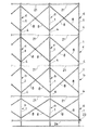
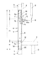
図1は、足場建枠a〜dが本発明に係る足場建枠用連結具4によって上下複数段に連結された状態を示す正面図、図2は、上下複数段に連結された足場建枠a〜dが前後方向に所定間隔おきに配設された状態を示す側面図であり、図3は本発明に係る足場建枠用連結具4を示す。図1及び図2に示すように、各足場建枠a〜dは、左右一対の縦管1,1と、両縦管1,1をつなぐ横管2と、縦管1と横管2とに亘って取り付けられる補強杆3とからなる。
【0009】
足場建枠用連結具4は、図3及び図4に示すように、上端部に上側足場建枠bの縦管1に差し込まれる上部連結ピン7bを形成し、下端部に下側足場建枠aの縦管1に差し込まれる下部連結ピン7aを形成した連結杆7からなり、この連結杆7の上端部には、この連結杆7と、前後に対向して配置される足場建枠a〜dとの間に架け渡して当該連結杆7を補強する補強用筋かい8の端部のピン孔9を挿通して止着するためのロック爪10a付きピン10(止着部)が、連結杆7の長手方向に直角に突設されている。
【0010】
上記足場建枠用連結具4について図3及び図4を参照して詳細に説明すると、連結杆7は、全体が上下に貫通する円管状本体5を有し、この円管状本体5の長さ方向中央部側に短管部材6が嵌合されて溶接により円管状本体5に一体的に固着され、この短管部材6の上端から上方に延びる円管状本体5の上方部分が上部連結ピン7bを形成し、短管部材6の下端から下方に延びる円管状本体5の下方部分が下部連結ピン7aを形成している。
【0011】
そして、上記短管部材6と上下連結ピン7a,7bとの間に外周段部11,12を形成し、図4に示すように、上部連結ピン7bが差し込まれる上側足場建枠aの縦管1はその下端面が上側の外周段部11に当接することによって位置決めされ、また下部連結ピン6bが差し込まれる下側足場建枠bの縦管1はその上端面が下側の外周段部12に当接することによって位置決めされる。
【0012】
また図4に示すように、各連結杆7には、上部連結ピン7bの側面より突出すると共にその側面から内部に退入自在な係合突起12と、この係合突起12と一体に形成されて連結杆7のレバー孔13から突出するレバー杆14とが設けられていると共に、係合突起12とレバー杆14とを一体形成した一体構造物15を係合突起12及びレバー杆14の突出方向に付勢させるU字状の板ばね16が内蔵されている。
【0013】
また、連結杆7の下端部には下部連結ピン7aの側面より突出する連結用突起18が設けられ、下側足場建枠bの縦管1の上端部には連結用突起18に係合する連結孔19が設けられ、該連結用突起18は、U字状の板ばね20によって互いに連結されていると共に、その板ばね20によって下部連結ピン7aの側面から突出付勢されている。
【0014】
連結杆7の上端部に突設されたピン10(止着部)は、ばね付勢式ロック爪10aを有するもので、このピン10に補強用筋かい8の一端部を止着するにあたっては、補強用筋かい8の端部のピン孔9を図3の実線で示す位置から連結杆7のピン10に押し込むように挿通させると、このピン孔9の挿通時にロック爪10aが引っ込み、ピン孔9が図3の仮想線図示及び図4の実線図示のようにピン10の根元まで入ると、ロック爪10aがばね付勢力で図示のようなロック位置に突出して補強用筋かい8の端部を止着する。この補強用筋かい8の他端部は、この補強用筋かい8の一端部を止着する側の足場建枠用連結具4と前後に対向する側の足場建枠用連結具4によって連結される上側足場建枠bの縦管1の上端部に設けてある同様なロック爪10a付きピン10に止着される(図5参照)。
【0015】
上記足場建枠用連結具4の寸法の一例を示せば、図3に示すように、連結杆7の全長Lは350mm、この連結杆7の上下端部に形成される上部連結ピン7b及び下部連結ピン7aのそれぞれの長さnは85mm、連結杆7の全長から上下両連結ピン7a,7bを除いた部分の長さ(短管部材6の長さ)mは180mmとされる。因みに、従来の連結ピンでは、その全長が例えば200mm、上下ピン部のそれぞれ長さが85mmで、上側ピン部と下側ピン部との間の長さが30mmであるから、本発明に係る連結杆7を使用すれば、従来の連結ピンの使用時よりも、足場建枠の高さを約150mm高くすることができる。
【0016】
上記のように構成される足場建枠用連結具4を使用して足場建枠a〜dを上下に連結するには、図3及び図4に示すように、先ず、連結杆7の下部連結ピン7aを下側足場建枠aの縦管1上端部に差し込む。この際、連結杆7の下部連結ピン7a側面から突出している連結用突起18を板ばね20に抗して内方へ押し込んだ状態で下部連結ピン7aを縦管1の上端部に差し込むと、連結杆7の下側外周段部12が縦管1の上端面に当接した位置で連結用突起18が縦管1上端部の連結孔19に係合し、それにより連結杆7の下部連結ピン7aが下側足場建枠aの縦管1にロックされて、足場建枠用連結具4が下側足場建枠aに固定される。尚、下部連結ピン7aを縦管1から抜き出す際には、連結用突起18は板ばね20の付勢力に抗して指で縦管1内に没入させて連結用突起18と縦管1との係合状態を解除させればよい。
【0017】
次に、上記のように下側足場建枠aに固定させた足場建枠用連結具4の連結杆7の上部連結ピン7bに、上側足場建枠bの縦管1を差し込む。この際、差し込み途上で係合突起12と一体のレバー杆14を作業者の足先で下方側に且つ退入方向に押圧することによって係合突起12が連結杆7の内部に退入することになるから、上側足場建枠bの縦管1下端部が連結杆7に挿入されるのを許し、しかして縦管1下端部の係合孔17に係合突起12が面する位置まで挿入されると、この係合突起12は板ばね16により付勢突出して係合孔17に係合し、連結杆7の上部連結ピン7bが上側足場建枠bの縦管1にロックされ、それによって上下の足場建枠a,bが互いに連結されることになる。以上は足場建枠a,b相互の連結について説明したが、足場建枠b〜d相互の連結についても上記と同様に行う。
【0018】
こうして足場建枠a〜dを足場建枠用連結具4によって上下複数段に連結すると共に、この上下複数段に連結した足場建枠a〜dを前後方向に複数組枠組みし、しかして図5に示すように前後に対向する各段の足場建枠a〜d相互間に補強用筋かい8をX字状に張架する。この場合、補強用筋かい8の一端部(ピン孔9)は、足場建枠用連結具4の連結杆7に設けてある止着部(ピン10)に止着し、その他端部(ピン孔)は、この補強用筋かい8の一端部を止着する側の足場建枠用連結具4と前後に対向する側の足場建枠用連結具4によって連結される足場建枠a〜dの縦管1の上端部に設けてある同様な止着部(ピン)に止着する。
【0019】
上記のようにして前後に対向する各段の足場建枠a〜d相互間に補強用筋かい8をX字状に張架した後、前後に対向する各段の足場建枠a〜d相互間における横管2,2に足場板21をフック22を介して架け渡す。尚、図1及び図2において、23及び24は根がらみ用単管で、足場建枠aの縦管1にそれぞれパイプクランプで取り付けられる。
【0020】
以上のように下側足場建枠aの縦管1上端部と上側足場建枠bの縦管1下端部とが足場建枠用連結具5により連結されることによって(他の足場建枠c,dについても同じ)、上側足場建枠bの高さが連結杆7の短管部材6長さ分だけ高くなる。この場合、短管部材6の長さが180mm程度、連結杆7の全長は350mm程度と従来の連結ピンに比べて相当長くなっているが、この足場建枠用連結具4の使用にあっては、足場建枠用連結具4の連結杆7と、前後に対向して配置される足場建枠との間に補強用筋かい8を架け渡すことによって、連結杆7を補強するようにしているから、足場建枠b〜dに作用する荷重や連結杆7と足場建枠a〜dの縦管1との嵌合隙間によって生ずる当該連結杆7の揺動を低減させ、それによって連結杆7の座屈を防止できると共に、枠組み足場全体の強度低下を抑制でき、それによってまた枠組み足場全体が構造的にきわめて安定したものとなり、使用上の安全が確保される。
【0021】
また、足場建枠用連結具4の連結杆7と、前後に対向して配置される足場建枠との間に補強用筋かい8を架け渡すにあたって、連結杆7の上端部側に止着部としてのロック爪10a付きピン10を突設し、このピン10に補強用筋かい8の一端部に設けてあるピン孔9を挿通させ、また補強用筋かい8の他端部はそのピン孔9を足場建枠a〜dの縦管1の上端部に設けてある同様なロック爪付きピンに挿通させるようにしているから、補強用筋かい8の架け渡し作業を簡単容易に行うことができると共に、補強用筋かい8の端部がその止着部から容易に外れることがなく、安全性を確保できる。
【0022】
また、以上の実施形態では、足場建枠用連結具4の上下連結ピン7a,7bを足場建枠a〜dの縦管1にそれぞれ差し込んだ状態でロックするロック手段についても説明しているが、このロック手段は一例を示したもので、これ以外のどのようなロック手段を使用してもよい。
【0023】
【発明の効果】
請求項1に係る発明の足場建枠用連結具は、上端部に上側足場建枠の縦管に差し込まれる上部連結ピンを形成し、下端部に下側足場建枠の縦管に差し込まれる下部連結ピンを形成した連結杆からなるもので、この連結杆に、この連結杆と、前後に対向して配置される足場建枠との間に架け渡して前記連結杆を補強する補強用筋かいの端部を止着するための止着部を設けているから、枠組足場における足場建枠の高さを高くすることができながら、連結杆と、前後に対向して配置される足場建枠との間に補強用筋かいを架け渡すことによって、足場建枠に作用する荷重や連結杆と足場建枠の縦管との嵌合隙間によって生ずる当該連結杆の揺動を低減させ、それによって連結杆の座屈を防止できると共に、枠組み足場全体の強度低下を抑制でき、それによってまた枠組み足場全体が構造的にきわめて安定したものとなり、使用上の安全を確保することができる。
【0024】
請求項2に記載のように、止着部が、補強用筋かいの端部に設けられたピン孔を挿通させるロック爪付きピンからなるため、連結杆への補強用筋かいの止着作業が簡単容易に行えると共に、補強用筋かいの端部がその止着部から容易に外れることがなく、安全性を確保できる。
【図面の簡単な説明】
【図1】足場建枠が本発明に係る足場建枠用連結具によって上下複数段に 連結された状態を示す正面図。
【図2】上下複数段に連結された足場建枠が前後方向に所定間隔おきに配 設された状態を示す側面図である。
【図3】足場建枠用連結具を示す拡大正面図である。
【図4】図1に矢印Aで囲まれる部分の足場建枠用連結具の一部断面拡大 正面図である。
【図5】足場建枠用連結具の連結杆と足場建枠の縦管とにわたって補強用筋かいが架け渡された状態を示す背面図である。
【符号の説明】
a,b,c,d 足場建枠
1 足場建枠の縦管
2 足場建枠の横管
3 補強杆
4 足場建枠用連結具
7 連結杆
7a 下部連結ピン
7b 上部連結ピン
8 補強用筋かい
9 ピン孔
10 ロック爪付きピン(止着部)
10a ロック爪[0001]
BACKGROUND OF THE INVENTION
TECHNICAL FIELD The present invention relates to a connector used to connect scaffold building frames up and down when temporarily constructing a frame scaffold with a scaffold building frame.
[0002]
[Prior art]
The scaffolding frame consists of a pair of left and right vertical pipes, a horizontal pipe that connects both vertical pipes, and a reinforcing rod that is attached across the vertical and horizontal pipes. A connecting means for connecting the scaffolding frames facing vertically is necessary. As this connection means, a connection pin in which upper and lower pin portions are inserted into the vertical pipe of the upper scaffold building frame and the vertical pipe of the lower scaffold building frame has been conventionally used.
[0003]
[Problems to be solved by the invention]
By the way, since the above-mentioned scaffold building frame uses a standard product that is quite old, the height of the scaffold building frame is considerably lower than the height of recent workers whose average height is high, Therefore, when an operator wears a helmet and passes through the framework scaffold, there is a disadvantage that the helmet hits the horizontal pipe of the scaffold building frame. In order to eliminate such inconvenience, if it is going to be rebuilt to a tall scaffolding frame, the production cost will be enormous and the scaffolding frame currently used will be wasted. Disposal is also very troublesome.
[0004]
Therefore, the present inventor uses a long connection pin that is longer than the length of the connection pin that connects the scaffold building frame up and down, thereby increasing the height of each scaffold building frame in the frame scaffold. However, when such a long connecting pin is used, the length of the connecting pin becomes longer, which causes a new problem that the buckling strength of the support pillar as a scaffold is lowered. Yes. This is because the connecting pin swings due to a load acting on the scaffold building frame and a gap necessary for fitting between the connecting pin and the scaffold building frame, and buckling is likely to occur.
[0005]
In the present invention, the long connecting pins (connecting rods) as described above are used alone so that the height of each scaffold building frame in the framework scaffold is increased. An object of the present invention is to provide a scaffold building frame connector that can reduce the swing of the connecting pin caused by the fitting gap between the scaffold building frame and the vertical pipe, and can suppress a decrease in strength of the entire framework scaffold.
[0006]
[Means for Solving the Problems]
The scaffold building frame connector according to the first aspect of the present invention is a reinforcing
[0007]
The second aspect of the present invention is the scaffold building frame connector according to the first aspect, wherein the fastening portion is from a
[0008]
DETAILED DESCRIPTION OF THE INVENTION
FIG. 1 is a front view showing a state in which scaffold building frames a to d are connected to a plurality of upper and lower stages by a scaffold
[0009]
As shown in FIGS. 3 and 4, the scaffold
[0010]
The scaffold
[0011]
And the outer
[0012]
As shown in FIG. 4, each connecting
[0013]
Further, a connecting
[0014]
A pin 10 (fastening portion) protruding from the upper end portion of the connecting
[0015]
If an example of the dimension of the said scaffold
[0016]
In order to connect the scaffold building frames a to d up and down using the scaffold
[0017]
Next, the
[0018]
In this way, the scaffold building frames a to d are connected to a plurality of upper and lower stages by the scaffold
[0019]
As described above, the reinforcing
[0020]
As described above, the upper end of the
[0021]
In addition, when the reinforcing
[0022]
Moreover, although the above embodiment also demonstrated the locking means which locks in the state which inserted the vertical connection pins 7a and 7b of the scaffold building
[0023]
【The invention's effect】
The connecting device for a scaffold building frame of the invention according to
[0024]
As described in
[Brief description of the drawings]
FIG. 1 is a front view showing a state in which a scaffold building frame is connected to a plurality of upper and lower stages by a scaffold building frame connector according to the present invention.
FIG. 2 is a side view showing a state in which scaffold building frames connected to a plurality of upper and lower stages are arranged at predetermined intervals in the front-rear direction.
FIG. 3 is an enlarged front view showing a scaffold building frame connector.
4 is an enlarged front view of a part of the scaffold building frame connector in a part surrounded by an arrow A in FIG. 1. FIG.
FIG. 5 is a rear view showing a state in which a reinforcing brace is stretched over the connecting rod of the scaffold building frame connector and the vertical pipe of the scaffold building frame.
[Explanation of symbols]
a, b, c,
10a Lock claw
Claims (2)
Priority Applications (1)
| Application Number | Priority Date | Filing Date | Title |
|---|---|---|---|
| JP21699599A JP3631400B2 (en) | 1999-07-30 | 1999-07-30 | Scaffolding frame connector |
Applications Claiming Priority (1)
| Application Number | Priority Date | Filing Date | Title |
|---|---|---|---|
| JP21699599A JP3631400B2 (en) | 1999-07-30 | 1999-07-30 | Scaffolding frame connector |
Publications (2)
| Publication Number | Publication Date |
|---|---|
| JP2001040871A JP2001040871A (en) | 2001-02-13 |
| JP3631400B2 true JP3631400B2 (en) | 2005-03-23 |
Family
ID=16697174
Family Applications (1)
| Application Number | Title | Priority Date | Filing Date |
|---|---|---|---|
| JP21699599A Expired - Fee Related JP3631400B2 (en) | 1999-07-30 | 1999-07-30 | Scaffolding frame connector |
Country Status (1)
| Country | Link |
|---|---|
| JP (1) | JP3631400B2 (en) |
Families Citing this family (3)
| Publication number | Priority date | Publication date | Assignee | Title |
|---|---|---|---|---|
| JP4020894B2 (en) * | 2004-07-08 | 2007-12-12 | アルインコ株式会社 | Aluminum scaffolding and scaffolding equipment |
| CN109184183B (en) * | 2018-09-05 | 2021-06-01 | 天长市华利机械实业有限公司 | Scaffold connecting assembly |
| CN113202275B (en) * | 2021-05-07 | 2022-05-31 | 中交一公局集团有限公司 | Coiled buckle support for continuous beam construction |
-
1999
- 1999-07-30 JP JP21699599A patent/JP3631400B2/en not_active Expired - Fee Related
Also Published As
| Publication number | Publication date |
|---|---|
| JP2001040871A (en) | 2001-02-13 |
Similar Documents
| Publication | Publication Date | Title |
|---|---|---|
| US5400870A (en) | Scaffolding frame system | |
| JP3631400B2 (en) | Scaffolding frame connector | |
| JP2017048602A (en) | Support structure of scaffold horizontal member and scaffold | |
| JP4996916B2 (en) | Installation method of wire mesh panel and handrail | |
| JP4042105B2 (en) | Scaffolding bracket | |
| JPH051468A (en) | Building frame for scaffold | |
| JP4387568B2 (en) | Temporary scaffold members such as overhang brackets | |
| JP3443035B2 (en) | Connecting pins for scaffolding frames | |
| JPH07292958A (en) | Joint of scaffolding frame | |
| JP4091608B2 (en) | Safety handrail | |
| JP2548893B2 (en) | Connecting pin for scaffolding frame | |
| JP4183730B2 (en) | Scaffolding board receiving member | |
| JP3939034B2 (en) | Scaffolding board receiving member | |
| JPH11152892A (en) | Handrail locking device for folding working table | |
| JP2530774B2 (en) | Connection device for building frame for scaffolding | |
| JP2543644B2 (en) | Connecting pin for scaffolding frame | |
| JP2543634B2 (en) | Single pipe connection device for temporary installation | |
| JP4023756B2 (en) | Wedge attachment method for temporary scaffolding brackets | |
| JP3981203B2 (en) | Handrail for H frame scaffolding | |
| JP3453196B2 (en) | Work scaffold | |
| JP3788407B2 (en) | Safety handrail | |
| JP3564404B2 (en) | Safety handrail | |
| JPH07207923A (en) | Handrail for end frame of framed scaffold | |
| JP2543651B2 (en) | Connecting pin for scaffolding frame | |
| JP2001003563A (en) | Coupler for scaffold building frames |
Legal Events
| Date | Code | Title | Description |
|---|---|---|---|
| A131 | Notification of reasons for refusal |
Free format text: JAPANESE INTERMEDIATE CODE: A131 Effective date: 20040206 |
|
| A521 | Written amendment |
Free format text: JAPANESE INTERMEDIATE CODE: A523 Effective date: 20040315 |
|
| A02 | Decision of refusal |
Free format text: JAPANESE INTERMEDIATE CODE: A02 Effective date: 20040409 |
|
| A521 | Written amendment |
Free format text: JAPANESE INTERMEDIATE CODE: A523 Effective date: 20040426 |
|
| A911 | Transfer of reconsideration by examiner before appeal (zenchi) |
Free format text: JAPANESE INTERMEDIATE CODE: A911 Effective date: 20040614 |
|
| A912 | Removal of reconsideration by examiner before appeal (zenchi) |
Free format text: JAPANESE INTERMEDIATE CODE: A912 Effective date: 20040709 |
|
| A61 | First payment of annual fees (during grant procedure) |
Free format text: JAPANESE INTERMEDIATE CODE: A61 Effective date: 20041216 |
|
| R150 | Certificate of patent or registration of utility model |
Ref document number: 3631400 Country of ref document: JP Free format text: JAPANESE INTERMEDIATE CODE: R150 Free format text: JAPANESE INTERMEDIATE CODE: R150 |
|
| FPAY | Renewal fee payment (event date is renewal date of database) |
Free format text: PAYMENT UNTIL: 20071224 Year of fee payment: 3 |
|
| FPAY | Renewal fee payment (event date is renewal date of database) |
Free format text: PAYMENT UNTIL: 20081224 Year of fee payment: 4 |
|
| R250 | Receipt of annual fees |
Free format text: JAPANESE INTERMEDIATE CODE: R250 |
|
| FPAY | Renewal fee payment (event date is renewal date of database) |
Free format text: PAYMENT UNTIL: 20081224 Year of fee payment: 4 |
|
| FPAY | Renewal fee payment (event date is renewal date of database) |
Free format text: PAYMENT UNTIL: 20091224 Year of fee payment: 5 |
|
| R250 | Receipt of annual fees |
Free format text: JAPANESE INTERMEDIATE CODE: R250 |
|
| FPAY | Renewal fee payment (event date is renewal date of database) |
Free format text: PAYMENT UNTIL: 20101224 Year of fee payment: 6 |
|
| R250 | Receipt of annual fees |
Free format text: JAPANESE INTERMEDIATE CODE: R250 |
|
| FPAY | Renewal fee payment (event date is renewal date of database) |
Free format text: PAYMENT UNTIL: 20101224 Year of fee payment: 6 |
|
| FPAY | Renewal fee payment (event date is renewal date of database) |
Free format text: PAYMENT UNTIL: 20111224 Year of fee payment: 7 |
|
| R250 | Receipt of annual fees |
Free format text: JAPANESE INTERMEDIATE CODE: R250 |
|
| FPAY | Renewal fee payment (event date is renewal date of database) |
Free format text: PAYMENT UNTIL: 20111224 Year of fee payment: 7 |
|
| FPAY | Renewal fee payment (event date is renewal date of database) |
Free format text: PAYMENT UNTIL: 20121224 Year of fee payment: 8 |
|
| R250 | Receipt of annual fees |
Free format text: JAPANESE INTERMEDIATE CODE: R250 |
|
| FPAY | Renewal fee payment (event date is renewal date of database) |
Free format text: PAYMENT UNTIL: 20121224 Year of fee payment: 8 |
|
| FPAY | Renewal fee payment (event date is renewal date of database) |
Free format text: PAYMENT UNTIL: 20131224 Year of fee payment: 9 |
|
| R250 | Receipt of annual fees |
Free format text: JAPANESE INTERMEDIATE CODE: R250 |
|
| R250 | Receipt of annual fees |
Free format text: JAPANESE INTERMEDIATE CODE: R250 |
|
| R250 | Receipt of annual fees |
Free format text: JAPANESE INTERMEDIATE CODE: R250 |
|
| R250 | Receipt of annual fees |
Free format text: JAPANESE INTERMEDIATE CODE: R250 |
|
| R250 | Receipt of annual fees |
Free format text: JAPANESE INTERMEDIATE CODE: R250 |
|
| R250 | Receipt of annual fees |
Free format text: JAPANESE INTERMEDIATE CODE: R250 |
|
| LAPS | Cancellation because of no payment of annual fees |