JP3630495B2 - Photo image processing device - Google Patents
Photo image processing device Download PDFInfo
- Publication number
- JP3630495B2 JP3630495B2 JP10527696A JP10527696A JP3630495B2 JP 3630495 B2 JP3630495 B2 JP 3630495B2 JP 10527696 A JP10527696 A JP 10527696A JP 10527696 A JP10527696 A JP 10527696A JP 3630495 B2 JP3630495 B2 JP 3630495B2
- Authority
- JP
- Japan
- Prior art keywords
- film
- carrier
- scanner
- image processing
- film carrier
- Prior art date
- Legal status (The legal status is an assumption and is not a legal conclusion. Google has not performed a legal analysis and makes no representation as to the accuracy of the status listed.)
- Expired - Fee Related
Links
Images


Classifications
-
- H—ELECTRICITY
- H04—ELECTRIC COMMUNICATION TECHNIQUE
- H04N—PICTORIAL COMMUNICATION, e.g. TELEVISION
- H04N1/00—Scanning, transmission or reproduction of documents or the like, e.g. facsimile transmission; Details thereof
- H04N1/04—Scanning arrangements, i.e. arrangements for the displacement of active reading or reproducing elements relative to the original or reproducing medium, or vice versa
- H04N1/0402—Scanning different formats; Scanning with different densities of dots per unit length, e.g. different numbers of dots per inch (dpi); Conversion of scanning standards
-
- H—ELECTRICITY
- H04—ELECTRIC COMMUNICATION TECHNIQUE
- H04N—PICTORIAL COMMUNICATION, e.g. TELEVISION
- H04N3/00—Scanning details of television systems; Combination thereof with generation of supply voltages
- H04N3/36—Scanning of motion picture films, e.g. for telecine
- H04N3/38—Scanning of motion picture films, e.g. for telecine with continuously moving film
-
- H—ELECTRICITY
- H04—ELECTRIC COMMUNICATION TECHNIQUE
- H04N—PICTORIAL COMMUNICATION, e.g. TELEVISION
- H04N5/00—Details of television systems
- H04N5/222—Studio circuitry; Studio devices; Studio equipment
- H04N5/253—Picture signal generating by scanning motion picture films or slide opaques, e.g. for telecine
-
- H—ELECTRICITY
- H04—ELECTRIC COMMUNICATION TECHNIQUE
- H04N—PICTORIAL COMMUNICATION, e.g. TELEVISION
- H04N1/00—Scanning, transmission or reproduction of documents or the like, e.g. facsimile transmission; Details thereof
- H04N1/04—Scanning arrangements, i.e. arrangements for the displacement of active reading or reproducing elements relative to the original or reproducing medium, or vice versa
- H04N1/12—Scanning arrangements, i.e. arrangements for the displacement of active reading or reproducing elements relative to the original or reproducing medium, or vice versa using the sheet-feed movement or the medium-advance or the drum-rotation movement as the slow scanning component, e.g. arrangements for the main-scanning
-
- H—ELECTRICITY
- H04—ELECTRIC COMMUNICATION TECHNIQUE
- H04N—PICTORIAL COMMUNICATION, e.g. TELEVISION
- H04N1/00—Scanning, transmission or reproduction of documents or the like, e.g. facsimile transmission; Details thereof
- H04N1/04—Scanning arrangements, i.e. arrangements for the displacement of active reading or reproducing elements relative to the original or reproducing medium, or vice versa
- H04N1/19—Scanning arrangements, i.e. arrangements for the displacement of active reading or reproducing elements relative to the original or reproducing medium, or vice versa using multi-element arrays
- H04N1/191—Scanning arrangements, i.e. arrangements for the displacement of active reading or reproducing elements relative to the original or reproducing medium, or vice versa using multi-element arrays the array comprising a one-dimensional array, or a combination of one-dimensional arrays, or a substantially one-dimensional array, e.g. an array of staggered elements
- H04N1/192—Simultaneously or substantially simultaneously scanning picture elements on one main scanning line
- H04N1/193—Simultaneously or substantially simultaneously scanning picture elements on one main scanning line using electrically scanned linear arrays, e.g. linear CCD arrays
-
- H—ELECTRICITY
- H04—ELECTRIC COMMUNICATION TECHNIQUE
- H04N—PICTORIAL COMMUNICATION, e.g. TELEVISION
- H04N2201/00—Indexing scheme relating to scanning, transmission or reproduction of documents or the like, and to details thereof
- H04N2201/0077—Types of the still picture apparatus
-
- H—ELECTRICITY
- H04—ELECTRIC COMMUNICATION TECHNIQUE
- H04N—PICTORIAL COMMUNICATION, e.g. TELEVISION
- H04N2201/00—Indexing scheme relating to scanning, transmission or reproduction of documents or the like, and to details thereof
- H04N2201/04—Scanning arrangements
- H04N2201/0402—Arrangements not specific to a particular one of the scanning methods covered by groups H04N1/04 - H04N1/207
- H04N2201/0404—Scanning transparent media, e.g. photographic film
- H04N2201/0408—Scanning film strips or rolls
-
- H—ELECTRICITY
- H04—ELECTRIC COMMUNICATION TECHNIQUE
- H04N—PICTORIAL COMMUNICATION, e.g. TELEVISION
- H04N2201/00—Indexing scheme relating to scanning, transmission or reproduction of documents or the like, and to details thereof
- H04N2201/04—Scanning arrangements
- H04N2201/0402—Arrangements not specific to a particular one of the scanning methods covered by groups H04N1/04 - H04N1/207
- H04N2201/0416—Performing a pre-scan
Description
【0001】
【発明の属する技術分野】
本発明はフィルムに記録された画像情報を読み取って表示する写真画像処理装置に関する。
【0002】
【従来の技術】
近年、カメラで撮影した画像を電子的ディジタル画像データに変換する写真画像処理システムが用いられるようになってきている。この種のシステムでは、カメラにより撮影し、現像されたフィルムをスキャナで読み込み、ディジタル画像データに変換し、記憶するようになっているものが多い。
【0003】
【発明が解決しようとする課題】
一方、現像されたフィルムの形態も様々であり、例えば、最も一般的なのはJ135ネガフィルムの場合で、6コマ毎に切断された形(以下、ピースフィルムという)でラボから返却されたり、またJ135リバーサルフィルムの場合は通常1コマ毎にマウントされた形(以下、マウントフィルムという)となっている。また、近年発表された新写真システムにおいては、現像されたフィルムがカートリッジ内に全て巻き取られた状態(以下、IX−240の長巻きフィルムという)でラボから返却される等、種類も多様化の傾向にある。従って、前述の写真画像処理システムの一つである写真画像処理装置においても、多様化する写真フィルムに対応しながらも、使いやすさ、見やすい画面等、ユーザの要望に応じた装置が求められている。
【0004】
本発明はこのような課題に鑑みてなされたものであって、画像情報を読み取って表示手段に表示する際に、フィルムの種類が例えばIX−240の長巻きフィルムである場合に、画像処理を効率よく行なうことができる写真画像処理装置を提供することを目的としている。
【0005】
【課題を解決するための手段】
(1) 前記した課題を解決する本発明は、現像されたフィルムが収納されたカートリッジフィルムの画像情報を読み取り手段により光学的に読み取って電気信号に変換する写真画像処理装置において、前記写真画像処理装置に挿入可能であり、前記カートリッジフィルムを装填可能なフィルムキャリアを有し、該フィルムキャリアには、フィルムを駆動する駆動手段と、該駆動手段に駆動力を与える駆動源と、該駆動源を制御するフィルム駆動制御手段と、外部と通信を行なう通信手段と、が備えられており、前記写真画像処理装置は、全体の制御を行なう制御手段と、前記フィルムキャリアを駆動して画像情報を読み込むスキャナとで構成され、前記フィルムキャリアを前記スキャナに挿入した時は、前記通信手段を経由して前記フィルムキャリアのフィルム駆動制御手段と通信を行なうように構成されており、前記制御手段は、前記スキャナに所定の制御指令を送ることにより、前記フィルムキャリアとの間で直接情報のやりとりを行なうことを特徴としている。
【0006】
この発明の構成によれば、フィルムキャリアに通信機能とフィルムの巻き上げ機能を持たせることによりカートリッジの装填性を向上し、処理手段により処理された画像情報を効率よく表示手段に表示することが可能となる。
【0007】
(2) この場合において、前記フィルムキャリアは画像読み込み用穴部を有し、前記フィルムが前記画像読み込み用穴部を覆わない状態で前記読み取り手段の光源からの照射光が前記画像読み込み用穴部を通過した時の読み取り手段の出力データをホワイトバランス調整に用いることを特徴としている。
【0008】
この発明の構成によれば、フィルムキャリアに形成されている画像読み込み用穴を利用してプレスキャン前にホワイトバランスをとることができるので、フィルムキャリアの構造を小型かつ簡単なものとすることができる。
【0009】
(3) また、前記写真画像処理装置は表示手段を有し、前記フィルムキャリアに保持されているフィルムのコマを連続プレスキャンして読み取り、読み取ったコマ画像情報を前記表示手段にインデックス表示することを特徴としている。
【0010】
この発明の構成によれば、フィルムを連続的にプレスキャンすることにより、読み取ったコマ画像情報を表示手段にインデックス表示することが可能となる。
【0012】
(4) 更に、前記フィルムキャリアの一部を外部に突出されるように駆動し、前記フィルムキャリア内のカートリッジを交換できる位置で停止させるイジェクト機能を有することを特徴としている。
【0013】
この発明の構成によれば、フィルムキャリアをスキャナに装着した状態でカートリッジを交換することができ、都合がよい。
【0014】
【発明の実施の形態】
以下、図面を参照して本発明の実施の形態例を詳細に説明する。
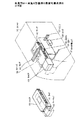
図1は本発明の一実施の形態例の電気的構成例を示すブロック図、図2は本発明の一実施の形態例の機械的構成例を示す図である。図2は透過図を示している。この実施の形態例では、写真画像処理装置はフィルムに記録されている画像情報を読み取るスキャナ部30と、画像情報を表示すると共に全体の動作の制御を行なうパソコン(パーソナルコンピュータ)部60と、スキャナ部30に装填されるキャリア40より構成されている。
【0015】
図2において、40はIX−240の長巻きフィルム(新写真システム用のフィルム)を格納しスキャナ内に挿入されるフィルムキャリア(以下単にキャリアという)である。同図には、キャリアの外観図と、キャリアがスキャナに挿入された状態を示す。該キャリア40は、図に示すようにカートリッジ形状をしており、データ通信機能とフィルムの巻き上げ、巻き戻し機能を具備している。30はスキャナ、31はスキャナ30内に設けられたキャリア挿入口である。32はスキャナ30内に設けられたキャリア40を装着して移動するステージである。
【0016】
41はキャリア40の側面に形成されたラック,33はスキャナ30内に設けられたプレスキャン駆動ギア(ピニオン)で、これらラックとピニオンとでラックアンドピニオン歯車を構成している。34はスキャナ30に取り付けられたフィルムのコマを照射するランプ、35は該ランプ34によりフィルムを透過した画像情報を反射するミラー、36は該ミラー35の反射光を集束するレンズ、37は該レンズ36により集束される光信号を受けて、電気信号に変換するCCDである。前記ランプ34はR,G,B毎に設けられており、CCD37は順次切り換えられるランプに応じてR,G,B毎に対応した色情報を受ける1個のモノクロ用のラインCCDである。そして、ステッピングモータで1ステップコマを送る毎に、先ずR照射で色情報を読み込み、次にG照射で色情報を読み込み、次にB照射で色情報を読み込むという処理を繰り返すものである。
【0017】
キャリア40には、現像済みフィルムが入ったカートリッジ42が装填され、駆動機構により1コマずつコマ送りすることができるようになっている。図1に示す装置は、スキャナ部30と制御手段としてのパーソナルコンピュータ(以下、パソコンという)部60より構成されている。スキャナ部において、1は全体の動作を制御するCPUである。RXD,TXDはキャリア40と接続されるデータ通信用の通信端子で、CPU1に接続されている。2はAC電源から回路に供給する電源を作る電源回路で、該電源回路2をオンにするためのスイッチSV が設けられている。SW1はCPU1をリセットするリセットスイッチである。
【0018】
4はパソコン60との間でデータのやりとりを行なうデータ通信部で、例えばSCSIインタフェースが用いられる。37はフィルムからの画像情報を読み取って電気信号に変換するCCD、5は該CCD37を駆動するCCDドライバである。CCD37としては、図2に示すようにラインCCDが用いられる。6はCCD37より読み取った画像信号をディジタル画像データに変換するA/D変換回路である。
【0019】
34はフィルムを照射するランプ、7は該ランプ34を駆動するランプドライバである。該ランプドライバ7はCPU1と接続され、R,G,B毎に設けられたランプ34を駆動するようになっている。8は前記ラックアンドピニオン機構を駆動する第1のステッピングモータ(SM1)、9はステージ32を駆動する第2のステッピングモータ、10はこれらステッピングモータ8,9を制御するステッピングモータドライバである。
【0020】
11はキャリアの位置を検知する第1の検知回路Aである。該検知回路11はキャリア40をスキャナ30に挿入した時に、初期位置の設定を行なうためのものであり、例えばフォトリフレクタ(P/R)が用いられる。
【0021】
パソコン60部において、20は全体の動作の制御を行なうCPU、20aは該CPU20内に設けられた読み取った画像データを記憶するメモリである。該メモリ20aには、表示手段に表示するプレスキャンで読み取ったフィルムの表示コマ数と、1コマ当たりの解像度データが予め記憶されている。21はスキャナ部30とデータのやりとりを行なうためのデータ通信部、22はCPU20に各種の操作を指令する操作部で、例えばキーボードやマウス等が用いられる。23はフィルムから読み込んだ画像を記憶するビデオメモリ、24は該ビデオメモリ23に記憶されている画像データを表示する表示手段としてのCRTである。このように構成された装置の動作を説明すれば、以下の通りである。
【0022】
先ず、キャリア40の構成・動作について説明する。
図3はキャリア40の電気的構成例を示すブロック図である。このユニットは、スキャナ30内に挿入されることにより、キャリア40とスキャナ30は接点を介して接続され、スキャナ30からパワーが供給されるようになっている。図のVDDとGND端子がそれである。図において、50は全体の動作を制御するCPU、51は該CPU50に動作クロックを与える発振回路、52はコマ送りする時にフィルムのパーホレーションを検出する第1の検知回路、53はフィルムの終了位置を検知する第2の検知回路である。54はCPU50からの制御信号を受けるモータドライバ、55は該モータドライバ54により駆動され、フィルムの巻き上げ、巻き戻しの駆動源となるDCモータである。RXD,TXDはスキャナ30内のCPU1(図1参照)と接続され、情報のやりとりを行なう通信端子である。このように構成された装置の動作を説明すれば、以下の通りである。
【0023】
先ずカートリッジ42が装填されたキャリア40をスキャナ30に装着すると、初期位置設定動作により図5の(b)の状態となって、キャリア40にパワーが供給されるようになる。これにより、CPU50はモータドライバ54に制御信号を送り、DCモータ55を回転させる。この結果、カートリッジ42からフィルムが繰り出され、フィルムは他端に向けて伸びていく。そして、DCモータ55により巻き取りスプールを回転させ、フィルムを巻き取る。第1の検知回路52により最初の1コマ目が所定の初期位置に到達したことを検知すると、CPU50は初期設定動作を終了する。プレスキャン動作に入ると、通信端子を介してスキャナ側CPU1から設定コマ数等の情報を受け取る。第1の検知回路52はフィルムのパーホレーションを検知し、CPU50は該検知回路52の出力を用いて、コマ位置から次のコマ位置までのコマ送り動作を制御する。
【0024】
(1) ホワイトバランス調整
図4はホワイトバランス調整動作を示すフローチャート、図5,図6はホワイトバランス調整動作の説明図である。図5において、11aは検知センサとしてのフォトリフレクタ、37はCCD、38は画像読み込み用穴である。オペレータは、キャリア挿入口31からキャリアを挿入する。検知回路11の一部である検知センサであるフォトリフレクタ(P/R)11aがキャリアが挿入されたかどうかを検知する(S1)。フォトリフレクタ11aがキャリアの挿入を検知すると、ステッピングモータ8を駆動してラックアンドピニオン機構によりキャリア40を初期位置まで後退させる(S2)。そして、フォトリフレクタ11aの検出出力があるかどうかチェックする(S3)。フォトリフレクタ11aの出力が無くなると、基準位置に到達したことになるので、CPU1はキャリア40を停止させる(S4)。図5の(b)はキャリア40が停止した状態を示している。この状態でカートリッジの通信端子はスキャナ部30と接続される。
【0025】
次に、キャリア40が停止した状態で、CPU1は通信確認を行なう(S5)。この通信確認は、キャリア40とスキャナ30との間で通信端子RXD,TXD(キャリア,スキャナの双方が具備している)を利用して通信が可能であるかどうかチェックするものである。通信不可の場合には、NG表示を行なう。通信が可能な場合には、ユーザはパソコン60部の操作部22よりプレスキャンスタートボタンを押して、プレスキャンを開始する(S6)。
【0026】
プレスキャン開始ボタンが押されると、この情報は、データ通信部21からスキャナ部のデータ通信部4を介してCPU1に通知される。CPU1は、ステージ駆動用のステッピングモータ9を駆動して、ステージ32を所定量だけ前進させる(S7)。図5の(c)はキャリア40が所定量だけ前進して、画像読み込み用穴38がCCD37の真上の位置まで来た状態を示している。この状態で、ランプ34を点灯して、CCD37を照射し、CCD37の出力を読み取る。この状態で、CCD37のホワイトバランス調整(ランプ出力調整及びシェーディング補正)を行なう(S8)。具体的には、CCD37で読み取られた光情報データは、A/D変換回路6でディジタル画像データに変換された後、データ通信部4からパソコン60部のCPU20に通知される。CPU20は、CCD37の出力データを受信して、ホワイトバランス調整動作を行なう。このように、本発明によれば、画像読み込み用穴38を利用して、プレスキャン前にホワイトバランス調整を行なうことができ、しかもフィルムキャリアの構造を小型かつ簡単なものとすることができる。
【0027】
ホワイトバランス調整が終了すると、CPU1はステッピングモータ9を駆動して、ステージ32を所定量だけ後退させ、基準位置に持ってくる(S9)。図6の(d)は基準位置状態を示している。次に、キャリア40内のCPU50は、DCモータ55を駆動し、フィルムのオートロード(巻き上げ)を行なう(S10)。図6の(e)はフィルムの巻き上げ状態を示し、(f)は画像読み込み用穴38に1コマ目のフィルム画像がはまり込み、画像読み込み状態にあることを示す。この状態で、CPU1はプレスキャンを行なう(S11)。
【0028】
(2) プレスキャン
図7はキャリアのプレスキャン動作を示すフローチャートである。IX−240フィルム(新写真システム用のフィルム)は、最大40コマあるので、先ずプレスキャンするコマ数Mをオペレータが操作部22から入力する(S1)。次に、プレスキャンを行なうかどうかをチェックし、操作部22からスキャン開始を指令すると、プレスキャンモードとなる(S2)。
【0029】
この場合には、先ず定数nを1に初期値設定する(S3)。次に、nが奇数かどうかチェックする(S4)。新写真フィルムの場合には、順方向スキャンと逆方向スキャンを順次繰り返しながら、所定のコマ数を粗い分解能で読み込むようになっている。コマ数が奇数の場合には、CPU1はステージ32をステッピングモータ9を駆動することにより、順方向(図7の左→右方向)に移動しながらコマ画像情報をCCD37で読み込む(S5)。この時にはステージ32が移動する。読み込まれた画像データは、データ通信部4を介してパソコン60部へ送られ、CPU20内のメモリ20aに格納される(S6)。次に、キャリア40は1コマ分巻き上げる。
【0030】
ステップS4において、該当コマが偶数である場合、CPU1はステージ32を今度は逆方向(右→左)に移動させてCCD37でコマ画像情報を読み込む(S7)。読み込まれた画像データは、データ通信部4を介してパソコン60部へ送られ、CPU20内のメモリ20aに格納される(S8)。コマ画像情報の1コマの読み込みが終了したら、CPU1はn=Mになったかどうかチェックする(S9)。n=Mとなった時には、指定された全てのコマ数の読み込みが終了したことになるので、プレスキャンを終了する。n≠Mの場合には、まだ全てのコマの読み込みが終了していないので、CPU1はステージ32を駆動して1コマ巻き上げを行なう(S10)。次に、nを1だけ更新した後(S11)、ステップS4に戻り、次のコマの読み込みを開始する。このような操作を繰り返してIX−240フィルムで連続プレスキャンを行なう。この実施の形態例によれば、フィルムを連続的にプレスキャンすることにより、読み取ったコマ画像情報を表示手段にインデックス表示することが可能となる。
【0031】
(3) CRTへのコマ画像表示
メモリ20aへのコマ画像データの取り込みが終了した後、CPU20は読み込んだコマ画像をCRT24にインデックス表示する。図8はCRTの画像の表示状態を示す図である。図に示すように1画面当たり9コマのインデックス表示を行なう。CRT24の分解能は、縦480ドット、横640ドットであり、これに対してインデックス表示されるコマ画像の解像度は、画像以外の表示領域及びレイアウト上のすきま等を考慮して110×200ドット程度となり、読取解像度は約170dpiとなる。
【0032】
従来、表示部への表示コマは1コマ毎にオペレータが行なっていた。複数のコマの中から、希望のコマを表示部に表示させるのには、特に現像フィルムがネガフィルムであった場合に該当コマを選択するには熟練が必要であった。複数コマを表示部に表示させる意味は、以下の通りである。例えば、ネガフィルムの場合、とりあえず早くポジ画像にしてオペレータにどのコマを本スキャンしたいのかを知らせる必要がある。それと、画面は小さくてもよいから、インデックス表示してどのような画像が写っているかをオペレータに知らせる必要がある。IX−240の長巻きフィルムの場合には、ネガフィルムがカートリッジに巻き取られているので、そのままの状態では、画像を見ようにも見れない。そこで、どのような画像が記録されているかをオペレータに早く見せてやるという必要がある。ただし、IX−240の記録コマ数である40コマ全部表示することは、1コマ当たりのコマがあまりにも小さくなってしまうので実用的ではない。そこで、撮影したコマ画像データを早く見たいという要求と、CRTに1回の操作でできる限り多くのコマ数を必要十分な解像度で表示したいという要求との妥協点として、前記したような1画面当たりの9コマの画像を表示するようにしたものである。
【0033】
一方、(c)に示すIX−240のフィルムの場合、最大40コマあるので、1回の表示では、全てのコマ数を表示しきれない。そこで、CPU20はこの場合のコマ数を頁で管理している。頁とコマの関係は以下の通りである。
【0034】
1頁目 1〜9
2頁目 10〜18
3頁目 19〜27
4頁目 28〜36
5頁目 37〜40
このように、CPU20はCRT24に希望の頁数を選択するメッセージ情報を表示させ、希望の頁をオペレータが操作部22から入力することにより、希望の頁のインデックス画像がCRT24に表示される。なお、このような操作をとらなくても、スクロール操作を行なうことにより、1頁から順次インデックス画像を表示させるようにすることもできる。
【0035】
(4) キャリアとパソコンとの間の直接通信
上述の実施の形態例では、キャリア40とパソコン(PC)60とはスキャナ30を介して情報のやりとりを行なう場合を例にとった。しかしながら、本発明はキャリア40とパソコン60との間の直接通信が可能である。図9は本発明の信号のやりとりの説明図である。パソコン60と、スキャナ30と、キャリア40との間の関係を示している。通常のスキャンにおいては、パソコン60から各制御命令(A〜X)により、パソコン60がスキャナ30をコントロールし、それに対する戻り値(a〜x)をスキャナ30がパソコン60に戻すことにより、パソコン60によりスキャナ30を制御するようになっている。
【0036】
このような制御命令コードと、その戻り値は例えば4ビットを用いて構成することができる。例えば、命令コード“A”は“0000”、命令コードBは“0001”、命令コードCは“0010”という具合である。戻り値も、同様に4ビットを用いて構成することができる。この制御命令のうち、“X”は、キャリア制御命令であり、図10に示すような流れにより、スキャナ30が介在せずにパソコン60はキャリア40の直接制御が可能である。キャリア制御命令コードとしては、例えば“1111”が用いられる。
【0037】
先ず、パソコンからスキャナに向けて、キャリア制御命令“X”をスキャナに与える。これに対してスキャナでは、この命令“X”がキャリア制御命令であることを認識すると、以降の制御を行なわない旨の戻り値“x”をパソコンに返す。これにより、以降、パソコンとキャリアとの間で直接通信が可能となる。例えば、パソコンからキャリアの制御命令である“あ”を発行すると、この制御命令はスキャナで受け取られ、該スキャナはこのコードをそのままキャリアに送る。キャリアは、この命令を受けて、このコードに対する動作を行ない、動作終了後、この動作に対する戻り値“ア”をそのままスキャナに返す。スキャナは、受け取った戻り値“ア”をそのままパソコンに返す。
【0038】
図11はキャリア制御命令コードと、キャリアの戻り値を示す図である。これらキャリア制御命令コードと戻り値も、例えば4ビットを用いて構成することができる。制御コード“あ”はオートロード実行命令、“い”は1コマ巻き上げ命令、“う”は1コマ巻き戻し命令、“え”は巻き込み実行命令、“お”はバージョンナンバ要求命令である。これに対して、キャリアから返される戻り値は、“ア”が正常終了情報、“イ”が異常終了(タイムオーバ)情報、“ウ”が異常終了(動作異常)情報である。なお、命令系統を元の状態に復帰させる場合には、パソコンからスキャナに向けて復帰命令コード、例えば“Q”を与える。スキャナは、この命令コードを受けると、戻り値“q”をパソコンに返し、以下パソコン60とスキャナ30との通信が開始されることになる。このように、本発明によれば、制御手段としてのパソコンとフィルムキャリアとの間で情報のやりとりを行なうことが可能となり、仕様を変更した時にも、スキャナを変更する必要がなくなる。
【0039】
(5) カートリッジの装填
本発明によれば、キャリアをスキャナに装着した状態で、カートリッジを交換することが可能である。図12はカートリッジ交換の説明図である。プレスキャン等により画像を読み込む場合には、(a)に示すように、カートリッジ42はスキャナ30内に隠れる。これに対して、イジェクト時には(b)に示すように、イジェクト機能によりカートリッジ42はスキャナ30より外側にはみ出る。そこで、(b)に示す状態で、キャリア40のカートリッジ部の蓋を開けることにより、装填されていたカートリッジ42を取り外し、新しいカートリッジを装填することができる。このように、本発明によれば、フィルムキャリアをスキャナに装着した状態でカートリッジを交換することができ、都合がよい。
【0040】
上述の実施の形態例では、スキャナ部とパソコン部とを分離した形態のものについて説明したが、本発明はこれに限るものではなく、スキャナ部とパソコン部とが一体化されているものであってもよい。
【0041】
【発明の効果】
(1) 以上、詳細に説明したように、本発明によれば、現像されたフィルムが収納されたカートリッジフィルムの画像情報を読み取り手段により光学的に読み取って電気信号に変換する写真画像処理装置において、前記写真画像処理装置に挿入可能であり、前記カートリッジフィルムを装填可能なフィルムキャリアを有し、該フィルムキャリアには、フィルムを駆動する駆動手段と、該駆動手段に駆動力を与える駆動源と、該駆動源を制御するフィルム駆動制御手段と、外部と通信を行なう通信手段と、が備えられており、前記写真画像処理装置は、全体の制御を行なう制御手段と、前記フィルムキャリアを駆動して画像情報を読み込むスキャナとで構成され、前記フィルムキャリアを前記スキャナに挿入した時は、前記通信手段を経由して前記フィルムキャリアのフィルム駆動制御手段と通信を行なうように構成されており、前記制御手段は、前記スキャナに所定の制御指令を送ることにより、前記フィルムキャリアとの間で直接情報のやりとりを行なうこで、フィルムキャリアに通信機能とフィルムの巻き上げ機能を持たせることによりカートリッジの装填性を向上し、処理手段により処理された画像情報を効率よく表示手段に表示することが可能となる。また、仕様を変更した時にも、スキャナを変更する必要がなくなる。
【0042】
(2) この場合において、前記フィルムキャリアは画像読み込み用穴部を有し、前記フィルムが前記画像読み込み用穴部を覆わない状態で前記読み取り手段の光源からの照射光が前記画像読み込み用穴部を通過した時の読み取り手段の出力データをホワイトバランス調整に用いることにより、フィルムキャリアに形成されている画像読み込み用穴を利用してプレスキャン前にホワイトバランスをとることができるので、フィルムキャリアの構造を小型かつ簡単なものとすることができる。
【0043】
(3) また、前記写真画像処理装置は表示手段を有し、前記フィルムキャリアに保持されているフィルムのコマを連続プレスキャンして読み取り、読み取ったコマ画像情報を前記表示手段にインデックス表示することにより、フィルムを連続的にプレスキャンすることにより、読み取ったコマ画像情報を表示手段にインデックス表示することが可能となる。
【0045】
(4) 更に、前記フィルムキャリアの一部を外部に突出させるように駆動し、前記フィルムキャリア内のカートリッジを交換できる位置で停止させるイジェクト機能を有することにより、フィルムキャリアをスキャナに装着した状態でカートリッジを交換することができ、都合がよい。
【0046】
このように、本発明によれば、画像情報を読み取って表示手段に表示する際に、フィルムの種類がIX−240等のような長巻きフィルムである場合に、画像処理を効率よく行なうことができる写真画像処理装置を提供することができる。
【図面の簡単な説明】
【図1】本発明の一実施の形態例の電気的構成例を示すブロック図である。
【図2】本発明の一実施の形態例の機械的構成例を示す図である。
【図3】キャリアの電気的構成例を示すブロック図である。
【図4】ホワイトバランス調整動作を示すフローチャートである。
【図5】ホワイトバランス調整動作の説明図である。
【図6】ホワイトバランス調整動作の説明図である。
【図7】キャリアのプレスキャン動作を示すフローチャートである。
【図8】CRTへのコマ画像表示例を示す図である。
【図9】本発明の信号のやりとりの説明図である。
【図10】本発明による通信プロトコルの説明図である。
【図11】キャリア制御命令コードとキャリアの戻り値を示す図である。
【図12】カートリッジ交換の説明図である。
【符号の説明】
1 CPU
2 電源回路
4 データ通信部
5 CCDドライバ
6 A/D変換回路
7 ランプドライバ
8 ステッピングモータ
9 ステッピングモータ
10 ステッピングモータドライバ
11 検知回路
20 CPU
20a メモリ
22 操作部
23 ビデオメモリ
24 CRT
34 ランプ
37 CCD[0001]
BACKGROUND OF THE INVENTION
The present invention relates to a photographic image processing apparatus that reads and displays image information recorded on a film.
[0002]
[Prior art]
In recent years, a photographic image processing system that converts an image captured by a camera into electronic digital image data has been used. In many systems of this type, a film shot and developed by a camera is read by a scanner, converted into digital image data, and stored.
[0003]
[Problems to be solved by the invention]
On the other hand, the developed film has various forms. For example, the most common is a J135 negative film, which is returned from the laboratory in a form cut every six frames (hereinafter referred to as a piece film), or J135. In the case of a reversal film, it is usually mounted in one frame (hereinafter referred to as a mount film). In addition, in the new photographic system announced in recent years, the variety of types has been diversified, for example, the developed film is returned from the laboratory in a state where all the developed film is wound up in a cartridge (hereinafter referred to as a long roll film of IX-240). Tend to. Therefore, in the photographic image processing apparatus which is one of the photographic image processing systems described above, there is a demand for an apparatus that meets the needs of the user, such as ease of use and easy-to-see screens, while supporting a variety of photographic films. Yes.
[0004]
The present invention has been made in view of such problems, and when the image information is read and displayed on the display means, the type of film isFor exampleAn object of the present invention is to provide a photographic image processing apparatus capable of efficiently performing image processing when it is a long roll film of IX-240.
[0005]
[Means for Solving the Problems]
(1) The present invention for solving the above-described problems is a photographic image processing apparatus for optically reading image information of a cartridge film containing a developed film by a reading means and converting it into an electric signal. A film carrier that can be inserted into the apparatus and into which the cartridge film can be loaded. The film carrier includes a driving unit that drives the film, a driving source that applies a driving force to the driving unit, and the driving source. A film drive control means for controlling, and a communication means for communicating with the outside,The photographic image processing apparatus comprises control means for performing overall control, and a scanner that reads the image information by driving the film carrier,The film carrierScannerWhen inserted into the film carrier, it is configured to communicate with the film drive control means of the film carrier via the communication means.The control means directly exchanges information with the film carrier by sending a predetermined control command to the scanner.It is characterized by that.
[0006]
According to the configuration of the present invention, the film carrier can be provided with a communication function and a film winding function so that the cartridge can be easily loaded, and the image information processed by the processing means can be efficiently displayed on the display means. It becomes.
[0007]
(2) In this case, the film carrier has an image reading hole, and the irradiation light from the light source of the reading means is in the state where the film does not cover the image reading hole. The output data of the reading means when passing through is used for white balance adjustment.
[0008]
According to the configuration of the present invention, since the white balance can be obtained before the pre-scanning using the image reading hole formed in the film carrier, the structure of the film carrier can be made small and simple. it can.
[0009]
(3) Further, the photographic image processing apparatus has display means, reads the film frames held on the film carrier by continuous pre-scanning, and displays the read frame image information as an index on the display means. It is characterized by.
[0010]
According to the configuration of the present invention, it is possible to display the read frame image information as an index on the display means by continuously pre-scanning the film.
[0012]
(4) Further, the present invention is characterized in that a part of the film carrier is driven so as to be protruded to the outside, and an ejecting function for stopping the cartridge in the film carrier at a position where it can be replaced is provided.
[0013]
According to the configuration of the present invention, the cartridge can be exchanged with the film carrier mounted on the scanner, which is convenient.
[0014]
DETAILED DESCRIPTION OF THE INVENTION
Hereinafter, embodiments of the present invention will be described in detail with reference to the drawings.
FIG. 1 is a block diagram showing an example of an electrical configuration of an embodiment of the present invention, and FIG. 2 is a diagram showing an example of a mechanical configuration of an embodiment of the present invention. FIG. 2 shows a transmission diagram. In this embodiment, the photographic image processing apparatus includes a
[0015]
In FIG. 2,
[0016]
41 is a rack formed on the side surface of the
[0017]
The
[0018]
[0019]
Reference numeral 34 denotes a lamp that irradiates the film, and reference numeral 7 denotes a lamp driver that drives the lamp 34. The lamp driver 7 is connected to the
[0020]
[0021]
In the
[0022]
First, the configuration and operation of the
FIG. 3 is a block diagram showing an example of the electrical configuration of the
[0023]
First, when the
[0024]
(1) White balance adjustment
FIG. 4 is a flowchart showing the white balance adjustment operation, and FIGS. 5 and 6 are explanatory diagrams of the white balance adjustment operation. In FIG. 5, 11a is a photo reflector as a detection sensor, 37 is a CCD, and 38 is an image reading hole. The operator inserts a carrier from the carrier insertion port 31. A photo reflector (P / R) 11a, which is a detection sensor that is a part of the
[0025]
Next, with the
[0026]
When the pre-scan start button is pressed, this information is notified from the data communication unit 21 to the
[0027]
When the white balance adjustment is completed, the
[0028]
(2) Pre-scan
FIG. 7 is a flowchart showing the carrier pre-scan operation. Since there are a maximum of 40 frames of IX-240 film (film for a new photographic system), the operator first inputs the number M of frames to be pre-scanned from the operation unit 22 (S1). Next, it is checked whether or not pre-scanning is to be performed, and when a start of scanning is commanded from the operation unit 22, a pre-scan mode is set (S2).
[0029]
In this case, first, a constant n is set to 1 (S3). Next, it is checked whether n is an odd number (S4). In the case of a new photographic film, a predetermined number of frames are read with a coarse resolution while sequentially repeating a forward scan and a reverse scan. When the number of frames is an odd number, the
[0030]
In step S4, if the corresponding frame is an even number, the
[0031]
(3) Frame image display on CRT
After the frame image data has been taken into the memory 20a, the
[0032]
Conventionally, an operator performs display frames on the display unit for each frame. In order to display a desired frame from a plurality of frames on the display unit, skill is required to select the corresponding frame particularly when the developing film is a negative film. The meaning of displaying a plurality of frames on the display unit is as follows. For example, in the case of a negative film, it is necessary to make a positive image as soon as possible and inform the operator which frame is to be scanned. In addition, since the screen may be small, it is necessary to display an index to inform the operator what kind of image is captured. In the case of a long roll film of IX-240, since the negative film is wound around the cartridge, it is impossible to see the image as it is. Therefore, it is necessary to quickly show the operator what kind of image is recorded. However, displaying all 40 frames, which is the number of recorded frames of IX-240, is not practical because the frames per frame are too small. Therefore, as a compromise between the request to view captured frame image data quickly and the request to display as many frames as possible on the CRT with the necessary and sufficient resolution, one screen as described above. A winning 9-frame image is displayed.
[0033]
On the other hand, in the case of the IX-240 film shown in (c), there are a maximum of 40 frames. Therefore, the
[0034]
1st page 1-9
2nd page 10-18
Page 3 19-27
4th page 28-36
5th page 37-40
As described above, the
[0035]
(4) Direct communication between carrier and PC
In the above-described embodiment, the case where the
[0036]
Such a control instruction code and its return value can be configured using, for example, 4 bits. For example, the instruction code “A” is “0000”, the instruction code B is “0001”, the instruction code C is “0010”, and so on. Similarly, the return value can be configured using 4 bits. Among these control commands, “X” is a carrier control command, and the
[0037]
First, a carrier control command “X” is given to the scanner from the personal computer to the scanner. On the other hand, when the scanner recognizes that the command “X” is a carrier control command, it returns a return value “x” indicating that the subsequent control is not performed to the personal computer. Thereby, direct communication is possible between the personal computer and the carrier thereafter. For example, when “A”, which is a carrier control command, is issued from a personal computer, this control command is received by the scanner, and the scanner sends this code to the carrier as it is. Upon receiving this command, the carrier performs an operation for this code, and after the operation is completed, returns the return value “a” for this operation to the scanner as it is. The scanner returns the received return value “A” as it is to the personal computer.
[0038]
FIG. 11 is a diagram showing a carrier control instruction code and a carrier return value. These carrier control instruction codes and return values can also be configured using, for example, 4 bits. The control code “A” is an autoload execution instruction, “I” is a single frame rewind instruction, “U” is a single frame rewind instruction, “E” is a rewind execution instruction, and “O” is a version number request instruction. On the other hand, the return values returned from the carrier are “a” for normal end information, “a” for abnormal end (time over) information, and “c” for abnormal end (operation abnormal) information. When the instruction system is returned to the original state, a return instruction code such as “Q” is given from the personal computer to the scanner. Upon receiving this instruction code, the scanner returns a return value “q” to the personal computer, and communication between the
[0039]
(5) Loading the cartridge
According to the present invention, it is possible to replace the cartridge with the carrier mounted on the scanner. FIG. 12 is an explanatory diagram of cartridge replacement. When an image is read by pre-scanning or the like, the cartridge 42 is hidden in the
[0040]
In the above embodiment, the scanner unit and the personal computer unit are separated from each other. However, the present invention is not limited to this, and the scanner unit and the personal computer unit are integrated. May be.
[0041]
【The invention's effect】
(1) As described above in detail, according to the present invention, in the photographic image processing apparatus that optically reads the image information of the cartridge film containing the developed film and converts the image information into an electrical signal. A film carrier that can be inserted into the photographic image processing apparatus and into which the cartridge film can be loaded. The film carrier includes a driving unit that drives the film, and a driving source that applies a driving force to the driving unit. A film drive control means for controlling the drive source and a communication means for communicating with the outside,The photographic image processing apparatus comprises control means for performing overall control, and a scanner that reads the image information by driving the film carrier,The film carrierScannerWhen inserted into the film carrier, it is configured to communicate with the film drive control means of the film carrier via the communication means.The control means directly exchanges information with the film carrier by sending a predetermined control command to the scanner.To dosoBy providing the film carrier with a communication function and a film winding function, the cartridge can be easily loaded, and the image information processed by the processing means can be efficiently displayed on the display means.Also, it is not necessary to change the scanner when the specification is changed.
[0042]
(2) In this case, the film carrier has an image reading hole, and the irradiation light from the light source of the reading means is in the state where the film does not cover the image reading hole. By using the output data of the reading means when passing through for white balance adjustment, white balance can be taken before pre-scanning using the image reading hole formed in the film carrier. The structure can be made small and simple.
[0043]
(3) Further, the photographic image processing apparatus has display means, reads the film frames held on the film carrier by continuous pre-scanning, and displays the read frame image information as an index on the display means. Thus, by continuously pre-scanning the film, the read frame image information can be displayed as an index on the display means.
[0045]
(4) In addition, the cartridge can be replaced while the film carrier is mounted on the scanner by having an eject function that drives the film carrier so that a part of the film carrier protrudes to the outside and stops the cartridge in the film carrier. Can be convenient.
[0046]
Thus, according to the present invention, when the image information is read and displayed on the display means, the film type is IX-240.Such asIn the case of a long film, a photographic image processing apparatus capable of efficiently performing image processing can be provided.
[Brief description of the drawings]
FIG. 1 is a block diagram showing an example of the electrical configuration of an embodiment of the present invention.
FIG. 2 is a diagram showing a mechanical configuration example of an embodiment of the present invention.
FIG. 3 is a block diagram illustrating an example of an electrical configuration of a carrier.
FIG. 4 is a flowchart showing a white balance adjustment operation.
FIG. 5 is an explanatory diagram of a white balance adjustment operation.
FIG. 6 is an explanatory diagram of a white balance adjustment operation.
FIG. 7 is a flowchart showing a carrier pre-scan operation.
FIG. 8 is a diagram illustrating an example of displaying a frame image on a CRT.
FIG. 9 is an explanatory diagram of signal exchange according to the present invention.
FIG. 10 is an explanatory diagram of a communication protocol according to the present invention.
FIG. 11 is a diagram illustrating a carrier control instruction code and a carrier return value.
FIG. 12 is an explanatory diagram of cartridge replacement.
[Explanation of symbols]
1 CPU
2 Power supply circuit
4 Data communication department
5 CCD driver
6 A / D conversion circuit
7 Lamp driver
8 Stepping motor
9 Stepping motor
10 Stepping motor driver
11 Detection circuit
20 CPU
20a memory
22 Operation unit
23 Video memory
24 CRT
34 Lamp
37 CCD
Claims (4)
前記写真画像処理装置に挿入可能であり、前記カートリッジフィルムを装填可能なフィルムキャリアを有し、
該フィルムキャリアには、
フィルムを駆動する駆動手段と、
該駆動手段に駆動力を与える駆動源と、
該駆動源を制御するフィルム駆動制御手段と、
外部と通信を行なう通信手段と、
が備えられており、
前記写真画像処理装置は、全体の制御を行なう制御手段と、前記フィルムキャリアを駆動して画像情報を読み込むスキャナとで構成され、
前記フィルムキャリアを前記スキャナに挿入した時は、前記通信手段を経由して前記フィルムキャリアのフィルム駆動制御手段と通信を行なうように構成されており、
前記制御手段は、前記スキャナに所定の制御指令を送ることにより、前記フィルムキャリアとの間で直接情報のやりとりを行なうことを特徴とする写真画像処理装置。In a photographic image processing apparatus that optically reads image information of a cartridge film containing a developed film and converts it into an electrical signal by a reading means.
A film carrier that can be inserted into the photographic image processing apparatus and into which the cartridge film can be loaded;
The film carrier includes
Driving means for driving the film;
A driving source for applying a driving force to the driving means;
Film drive control means for controlling the drive source;
A communication means for communicating with the outside;
Is provided,
The photographic image processing apparatus comprises control means for performing overall control, and a scanner that reads the image information by driving the film carrier,
When the film carrier is inserted into the scanner , it is configured to communicate with the film drive control means of the film carrier via the communication means ,
The photographic image processing apparatus , wherein the control means directly exchanges information with the film carrier by sending a predetermined control command to the scanner .
Priority Applications (5)
| Application Number | Priority Date | Filing Date | Title |
|---|---|---|---|
| JP10527696A JP3630495B2 (en) | 1996-04-25 | 1996-04-25 | Photo image processing device |
| TW086104718A TW366435B (en) | 1996-04-25 | 1997-04-12 | Photographic image processing apparatus |
| US08/839,631 US5757420A (en) | 1996-04-25 | 1997-04-15 | Photographic image processing apparatus |
| DE69731139T DE69731139T2 (en) | 1996-04-25 | 1997-04-16 | Photographic image processing device |
| EP97106302A EP0804020B1 (en) | 1996-04-25 | 1997-04-16 | Photographic image processing apparatus |
Applications Claiming Priority (1)
| Application Number | Priority Date | Filing Date | Title |
|---|---|---|---|
| JP10527696A JP3630495B2 (en) | 1996-04-25 | 1996-04-25 | Photo image processing device |
Publications (2)
| Publication Number | Publication Date |
|---|---|
| JPH09292661A JPH09292661A (en) | 1997-11-11 |
| JP3630495B2 true JP3630495B2 (en) | 2005-03-16 |
Family
ID=14403156
Family Applications (1)
| Application Number | Title | Priority Date | Filing Date |
|---|---|---|---|
| JP10527696A Expired - Fee Related JP3630495B2 (en) | 1996-04-25 | 1996-04-25 | Photo image processing device |
Country Status (5)
| Country | Link |
|---|---|
| US (1) | US5757420A (en) |
| EP (1) | EP0804020B1 (en) |
| JP (1) | JP3630495B2 (en) |
| DE (1) | DE69731139T2 (en) |
| TW (1) | TW366435B (en) |
Families Citing this family (4)
| Publication number | Priority date | Publication date | Assignee | Title |
|---|---|---|---|---|
| JP3557294B2 (en) * | 1995-08-29 | 2004-08-25 | オリンパス株式会社 | Scanner device |
| JP3445438B2 (en) * | 1996-04-26 | 2003-09-08 | コニカ株式会社 | Photographic image display |
| FR2787667B1 (en) * | 1998-12-18 | 2001-02-16 | Eastman Kodak Co | VISUALIZATION OF PHOTOGRAPHS ON TELEVISION SCREEN USING A MAGNETOSCOPE |
| US20030002092A1 (en) * | 2001-06-28 | 2003-01-02 | Tecu Kirk Steven | System, method and adapter for scanning a roll of transparent media |
Family Cites Families (12)
| Publication number | Priority date | Publication date | Assignee | Title |
|---|---|---|---|---|
| BE775363R (en) * | 1971-04-23 | 1972-03-16 | Staar Dev Cy S A | SLIDE SUPPORT WITH ADDED SOUND RECORDINGS AND DEVICES ALLOWING SIMULTANEOUS VISION AND HEARING |
| US4656524A (en) * | 1985-12-23 | 1987-04-07 | Polaroid Corporation | Electronic imaging copier |
| US4858003A (en) * | 1988-01-12 | 1989-08-15 | Eastman Kodak Company | Mechanism for handling slides and film strips |
| US5371614A (en) * | 1989-11-01 | 1994-12-06 | Tokyo Electric Co., Ltd. | Image scanner for film |
| JP2964364B2 (en) * | 1990-09-14 | 1999-10-18 | 富士写真フイルム株式会社 | Film image input device |
| US5295204A (en) * | 1991-07-18 | 1994-03-15 | Eastman Kodak Company | Method for color balancing a computer input scanner incorporating multiple scanning modes |
| US5155586A (en) * | 1991-08-19 | 1992-10-13 | Sony Corporation Of America | Method and apparatus for flare correction |
| JPH05176275A (en) * | 1991-11-29 | 1993-07-13 | Minolta Camera Co Ltd | Film player |
| JP3371929B2 (en) * | 1994-08-25 | 2003-01-27 | 株式会社ニコン | Feeder for image input device |
| US5589953A (en) * | 1994-06-24 | 1996-12-31 | Nikon Corporation | Image input system having an auto-feeder including loading magazine and discharge magazine arranged side by side and method |
| US5486959A (en) * | 1994-07-12 | 1996-01-23 | Tai; David | Adapter mechanism for extracting and retracting video tape from miniature cassettes |
| JP3542175B2 (en) * | 1994-09-05 | 2004-07-14 | オリンパス株式会社 | Electronic film viewer device |
-
1996
- 1996-04-25 JP JP10527696A patent/JP3630495B2/en not_active Expired - Fee Related
-
1997
- 1997-04-12 TW TW086104718A patent/TW366435B/en active
- 1997-04-15 US US08/839,631 patent/US5757420A/en not_active Expired - Fee Related
- 1997-04-16 DE DE69731139T patent/DE69731139T2/en not_active Expired - Fee Related
- 1997-04-16 EP EP97106302A patent/EP0804020B1/en not_active Expired - Lifetime
Also Published As
| Publication number | Publication date |
|---|---|
| EP0804020A2 (en) | 1997-10-29 |
| DE69731139T2 (en) | 2005-10-13 |
| EP0804020B1 (en) | 2004-10-13 |
| JPH09292661A (en) | 1997-11-11 |
| US5757420A (en) | 1998-05-26 |
| TW366435B (en) | 1999-08-11 |
| EP0804020A3 (en) | 1999-01-13 |
| DE69731139D1 (en) | 2004-11-18 |
Similar Documents
| Publication | Publication Date | Title |
|---|---|---|
| US7532245B2 (en) | Digital printer and digital camera | |
| JP3510342B2 (en) | Camera system | |
| JP3630495B2 (en) | Photo image processing device | |
| US6205296B1 (en) | Film information writing device, film information reading device and film information handling device | |
| JPH118831A (en) | Composite photograph system, electronic camera with composite photographic function and recording medium | |
| JP3445438B2 (en) | Photographic image display | |
| US5805206A (en) | Film image processing apparatus | |
| JP3581516B2 (en) | Image processing apparatus and reading control method | |
| JPH10240916A (en) | Picture reading system, and storage medium for storing control procedure for the system | |
| JP2590898B2 (en) | Micro printer | |
| US6335808B1 (en) | Image reading apparatus | |
| JP3125324B2 (en) | Printer with photo image editing function | |
| JP2530890B2 (en) | Micro image processor | |
| JP2986817B2 (en) | Image reading device | |
| JPH09284487A (en) | Picture input device | |
| JPH1155440A (en) | Image input device | |
| JP2002162698A (en) | Film image reader | |
| JPH10239761A (en) | Photograph producing device | |
| JP2003237138A (en) | Printer | |
| WO2002003134A2 (en) | Photographic film scanning and pringting apparatus and method | |
| JPH1198440A (en) | Projector provided with printing function and method for printing image of the projector | |
| JPH09312733A (en) | Film scanner | |
| JP2003163808A (en) | Image reading apparatus, its control method, medium for providing control program, and the control program | |
| JP2005323184A (en) | Method and apparatus for outputting image | |
| JPH0832760A (en) | Film image input system |
Legal Events
| Date | Code | Title | Description |
|---|---|---|---|
| A521 | Written amendment |
Free format text: JAPANESE INTERMEDIATE CODE: A523 Effective date: 20040205 |
|
| A131 | Notification of reasons for refusal |
Free format text: JAPANESE INTERMEDIATE CODE: A131 Effective date: 20040810 |
|
| A521 | Written amendment |
Free format text: JAPANESE INTERMEDIATE CODE: A523 Effective date: 20041006 |
|
| TRDD | Decision of grant or rejection written | ||
| A01 | Written decision to grant a patent or to grant a registration (utility model) |
Free format text: JAPANESE INTERMEDIATE CODE: A01 Effective date: 20041207 |
|
| A61 | First payment of annual fees (during grant procedure) |
Free format text: JAPANESE INTERMEDIATE CODE: A61 Effective date: 20041214 |
|
| R150 | Certificate of patent or registration of utility model |
Free format text: JAPANESE INTERMEDIATE CODE: R150 |
|
| FPAY | Renewal fee payment (event date is renewal date of database) |
Free format text: PAYMENT UNTIL: 20071224 Year of fee payment: 3 |
|
| FPAY | Renewal fee payment (event date is renewal date of database) |
Free format text: PAYMENT UNTIL: 20081224 Year of fee payment: 4 |
|
| FPAY | Renewal fee payment (event date is renewal date of database) |
Free format text: PAYMENT UNTIL: 20081224 Year of fee payment: 4 |
|
| FPAY | Renewal fee payment (event date is renewal date of database) |
Free format text: PAYMENT UNTIL: 20091224 Year of fee payment: 5 |
|
| LAPS | Cancellation because of no payment of annual fees |