EP0804020B1 - Photographic image processing apparatus - Google Patents
Photographic image processing apparatus Download PDFInfo
- Publication number
- EP0804020B1 EP0804020B1 EP97106302A EP97106302A EP0804020B1 EP 0804020 B1 EP0804020 B1 EP 0804020B1 EP 97106302 A EP97106302 A EP 97106302A EP 97106302 A EP97106302 A EP 97106302A EP 0804020 B1 EP0804020 B1 EP 0804020B1
- Authority
- EP
- European Patent Office
- Prior art keywords
- film
- carrier
- scanner
- image
- reading
- Prior art date
- Legal status (The legal status is an assumption and is not a legal conclusion. Google has not performed a legal analysis and makes no representation as to the accuracy of the status listed.)
- Expired - Lifetime
Links
Images


Classifications
-
- H—ELECTRICITY
- H04—ELECTRIC COMMUNICATION TECHNIQUE
- H04N—PICTORIAL COMMUNICATION, e.g. TELEVISION
- H04N1/00—Scanning, transmission or reproduction of documents or the like, e.g. facsimile transmission; Details thereof
- H04N1/04—Scanning arrangements, i.e. arrangements for the displacement of active reading or reproducing elements relative to the original or reproducing medium, or vice versa
- H04N1/0402—Scanning different formats; Scanning with different densities of dots per unit length, e.g. different numbers of dots per inch (dpi); Conversion of scanning standards
-
- H—ELECTRICITY
- H04—ELECTRIC COMMUNICATION TECHNIQUE
- H04N—PICTORIAL COMMUNICATION, e.g. TELEVISION
- H04N3/00—Scanning details of television systems; Combination thereof with generation of supply voltages
- H04N3/36—Scanning of motion picture films, e.g. for telecine
- H04N3/38—Scanning of motion picture films, e.g. for telecine with continuously moving film
-
- H—ELECTRICITY
- H04—ELECTRIC COMMUNICATION TECHNIQUE
- H04N—PICTORIAL COMMUNICATION, e.g. TELEVISION
- H04N5/00—Details of television systems
- H04N5/222—Studio circuitry; Studio devices; Studio equipment
- H04N5/253—Picture signal generating by scanning motion picture films or slide opaques, e.g. for telecine
-
- H—ELECTRICITY
- H04—ELECTRIC COMMUNICATION TECHNIQUE
- H04N—PICTORIAL COMMUNICATION, e.g. TELEVISION
- H04N1/00—Scanning, transmission or reproduction of documents or the like, e.g. facsimile transmission; Details thereof
- H04N1/04—Scanning arrangements, i.e. arrangements for the displacement of active reading or reproducing elements relative to the original or reproducing medium, or vice versa
- H04N1/12—Scanning arrangements, i.e. arrangements for the displacement of active reading or reproducing elements relative to the original or reproducing medium, or vice versa using the sheet-feed movement or the medium-advance or the drum-rotation movement as the slow scanning component, e.g. arrangements for the main-scanning
-
- H—ELECTRICITY
- H04—ELECTRIC COMMUNICATION TECHNIQUE
- H04N—PICTORIAL COMMUNICATION, e.g. TELEVISION
- H04N1/00—Scanning, transmission or reproduction of documents or the like, e.g. facsimile transmission; Details thereof
- H04N1/04—Scanning arrangements, i.e. arrangements for the displacement of active reading or reproducing elements relative to the original or reproducing medium, or vice versa
- H04N1/19—Scanning arrangements, i.e. arrangements for the displacement of active reading or reproducing elements relative to the original or reproducing medium, or vice versa using multi-element arrays
- H04N1/191—Scanning arrangements, i.e. arrangements for the displacement of active reading or reproducing elements relative to the original or reproducing medium, or vice versa using multi-element arrays the array comprising a one-dimensional [1D] array
- H04N1/192—Simultaneously or substantially simultaneously scanning picture elements on one main scanning line
- H04N1/193—Simultaneously or substantially simultaneously scanning picture elements on one main scanning line using electrically scanned linear arrays, e.g. linear CCD arrays
-
- H—ELECTRICITY
- H04—ELECTRIC COMMUNICATION TECHNIQUE
- H04N—PICTORIAL COMMUNICATION, e.g. TELEVISION
- H04N2201/00—Indexing scheme relating to scanning, transmission or reproduction of documents or the like, and to details thereof
- H04N2201/0077—Types of the still picture apparatus
-
- H—ELECTRICITY
- H04—ELECTRIC COMMUNICATION TECHNIQUE
- H04N—PICTORIAL COMMUNICATION, e.g. TELEVISION
- H04N2201/00—Indexing scheme relating to scanning, transmission or reproduction of documents or the like, and to details thereof
- H04N2201/04—Scanning arrangements
- H04N2201/0402—Arrangements not specific to a particular one of the scanning methods covered by groups H04N1/04 - H04N1/207
- H04N2201/0404—Scanning transparent media, e.g. photographic film
- H04N2201/0408—Scanning film strips or rolls
-
- H—ELECTRICITY
- H04—ELECTRIC COMMUNICATION TECHNIQUE
- H04N—PICTORIAL COMMUNICATION, e.g. TELEVISION
- H04N2201/00—Indexing scheme relating to scanning, transmission or reproduction of documents or the like, and to details thereof
- H04N2201/04—Scanning arrangements
- H04N2201/0402—Arrangements not specific to a particular one of the scanning methods covered by groups H04N1/04 - H04N1/207
- H04N2201/0416—Performing a pre-scan
Definitions
- the present invention relates to a photographic image processing apparatus which reads image information recorded on a film and displays aforesaid image.
- the form of developed film are various.
- the most common form is J135 negative film, in which a film is returned from a photo-finishing laboratory in such a manner that the film is cut every 6 frames (hereinafter, referred to as a piece film).
- a mount film In the case of a J135 reversal film, each frame is mounted (hereinafter, referred to as a mount film).
- the developed film is returned from the lab in which the entire roll of film is wound in a cartridge (hereinafter, referred to as IX-240 long roll film).
- IX-240 long roll film As described above, the type of films has been diversified. Accordingly, in the photographic image processing apparatus which is one of the above-mentioned photographic image processing system, an apparatus which complies with customers' requests such as easy use and easy viewing in addition to cope with diversified photographic film.
- An objective of the present invention is to provide a photographic image processing apparatus capable of image-processing effectively when image information is read and to be displayed on a displaying means, if the type of film is an IX-240 long roll film.
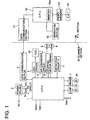
- Fig. 1 is a block diagram showing an electrical constitution example of the present invention.
- Figs 2(a) and 2(b) are drawings showing a mechanical constitution example of the present invention.
- Fig. 3 is a block diagram showing an electrical constitution example of the carrier.
- Fig. 4 is a flow chart showing an operation of white balance adjustment.
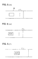
- Figs. 5(a) - 5(f) are explanation drawings showing operation of white balance adjustment.
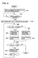
- Fig. 6 is a flow chart showing pre-scanning operation of the carrier.
- Fig. 7 is a drawing showing an example of frame image displaying onto the CRT.
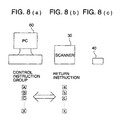
- Figs. 8(a) - 8(c) are explanation drawings showing communication of signals of the present invention.
- Fig. 9 is an explanation drawing of communication protocol of the present invention.
- Figs 10(a) and 10(b) are drawings showing the carrier control instruction codes and return instructions.
- Figs. 11(a) and 11(b) are explanation drawings of cartridge replacement.
- Fig. 1 is a block diagram showing an example of an electrical block diagram of the present invention.
- Figs. 2(a) and 2(b) are drawings showing mechanical structure of the example of the present invention.
- the photographic image processing apparatus comprises scanner section 30 which reads image information recorded on a film, personal computer section 60 which controls entire operation together with displaying image information and carrier 40 loaded onto scanner section 30.
- numeral 40 represents a film carrier (hereinafter, simply referred to as "carrier”) which houses a IX-240 long roll film (a film for an Advanced Photo System) and is inserted in a scanner.
- carrier a film carrier
- IX-240 long roll film a film for an Advanced Photo System
- FIG. 2(a) an external appearance drawing of the carrier and the status in which the carrier is inserted into the scanner are shown.
- Aforesaid carrier 40 is formed into a cartridge, as shown in Fig. 2(a), and comprises a data communication function and a film winding and rewinding function.
- Numeral 30 represents a scanner
- numeral 31 represents a carrier insertion port provided in scanner 30.
- Numeral 32 is a stage which loads carrier 40 provided inside scanner 30 and moves.
- Numeral 41 represents a rack formed on the side of carrier 40.
- Numeral 33 represents a pre-scanning driving gear (pinion) provided inside scanner 30. The above-mentioned rack and the pinion constitute a rack and pinion gear.
- Numeral 34 represents a lamp illuminating each frame of film mounted on scanner 30.
- Numeral 35 represents a mirror reflecting image information which is transmitted to a film by aforesaid lamp 34.
- Numeral 36 represents a lens converging reflected light beams from aforesaid mirror 35.
- Numeral 37 represents a CCD which receives optical signal converged by aforesaid lens 36 and which converts it to electrical signal.
- the above-mentioned lamp 34 is provided for each of R, G and B.
- the CCD 37 is a line CCD for monochromatic color which receives color information corresponding to each of R, G and B. Every time the film is fed by one frame by a stepping motor, color information is read by an R irradiation, followed by reading of color information by a G irradiation. Then, color information is read by a B irradiation, after which aforesaid process is repeated.
- FIG. 1 An apparatus shown in Fig. 1 is composed of scanner section 30 and personal computer 60 which serves as a control means.
- numeral 1 represents a CPU which controls entire operation.
- RXD and TXD represent a communication terminal for data communication which is connected with carrier 40, and they are connected to CPU 1.
- Numeral 2 represents an electrical power supply circuit which supplies electrical power from the AC power source to each circuit of scanner section 30 and carrier 40, in which a switch SV for actuating aforesaid electrical power supply circuit 2 is provided.
- SW1 represents a reset switch for resetting CPU 1.
- Numeral 4 represents a data communication section which communicates data with personal computer 60, and a SCSI interface is used.
- Numeral 37 represents a CCD which reads image information from a film and to converts it to electric signals.
- Numeral 5 represents a CCD driver which drives aforesaid CCD 37.
- CCD 37 a line CCD as shown in Fig. 2(a) is used.
- Numeral 6 represents an A/D converter circuit which converts an image signal read by CCD 37 into digital image data.
- Numeral 34 represents a lamp which irradiates a film.
- Numeral 7 represents a lamp driver which drives aforesaid lamp 34.
- Numeral 8 represents a first stepping motor (SM1) which drives the above-mentioned rack and pinion mechanism.
- Numeral 9 represents a second stepping motor which drives stage 32.
- Numeral 10 represents a stepping motor driver which controls stepping motors 8 and 9.
- Numeral 11 represents a first detecting circuit A which senses the position of a carrier.
- Aforesaid detecting circuit 11 is used for setting initial position when carrier 40 is inserted into scanner 30.
- a photo-sensor is used.
- numeral 20 represents a CPU which controls entire operation
- numeral 20a represents a memory which stores read image data provided in aforesaid CPU 20.
- aforesaid memory 20a displaying frame number of a film read by a pre-scanner displayed on a displaying means and resolution data per one frame is stored in advanced.
- Numeral 21 represents a data communication section for communicating data with scanner section 30.
- Numeral 22 represents an operation section which commands various kinds of operation on CPU 20. For example, a keyboard and a mouse are used.
- Numeral 23 represents a video memory which stores an image read from a film.
- Numeral 24 represents a CRT used as a display means which displays image data stored in aforesaid video memory. Operation of the apparatus constituted as above will now be explained.
- Fig. 3 is a block diagram showing electrical constitution example of carrier 40. Due to a structure that aforesaid unit is inserted into scanner 30, carrier 40 is connected with scanner 30 through a contact point so that power is supplied from scanner 30.
- VDD and GND are examples of aforesaid terminals.
- numeral 50 represents CPU which controls entire operation.
- Numeral 51 represents an oscillating circuit which provides operation clock to aforesaid CPU 50.
- Numeral 52 represents a first detecting circuit which senses film perforations when each frame is fed.
- Numeral 53 represents a second detecting circuit which detects finish position of a film.
- Numeral 54 represents a motor driver which receives a control signal from CPU 50.
- Numeral 55 represents a DC motor which is driven by aforesaid motor driver 54 for winding and rewinding the roll film.
- RXD and TXD are communication terminals which are connected with CPU 1 (see Fig. 1) inside scanner 30 for communicating information. Operation of an apparatus constituted as above is explained as follows.
- Fig. 4 represents a flow chart showing operation for a white balance adjustment.
- Figs. 5(a) - 5(f) are explanation drawings for the operation of white balance adjustment.
- numeral 11a represents a photosensor as a detecting sensor.
- Numeral 37 represents a CCD, and numeral 38 represents an aperture for reading an image.
- the operator inserts a carrier from carrier insertion port 31.
- Photosensor which is a detecting sensor, serves as a part of detecting circuit 11 detects whether or not the carrier has been inserted (S1).
- stepping motor 8 is activated so that carrier 40 return to the initial position by means of a rack and pinion mechanism (S2).
- CPU 1 conducts communication confirmation (S5).
- This communication confirmation checks whether or not communication between carrier 40 and scanner 30 is possible utilizing communication terminals RXD and TXD (both the carrier and the scanner provide them).
- RXD and TXD both the carrier and the scanner provide them.
- Message "impossible” is displayed.
- the operator presses a pre-scanning start button on operation section 22 on personal computer 60 for starting pre-scanning (S6).
- Fig. 5(c) shows a status in which carrier 40 advances by a prescribed amount and aperture 38 for image reading comes right above CCD 37. In this status, lamp 34 is lit, CCD 37 is irradiated and output from CCD 37 is read. Under this status, the adjustment of white balance of CCD 37 (lamp output adjustment and shading correction) are conducted (S8). Practically, optical information data read by CCD 37 is communicated to CPU 20 on personal computer 60 from data communication section 4 after aforesaid data is converted to digital image data in A/D conversion circuit 6.
- CPU 20 receives data outputted from CCD 37 and operates white balance adjustment. As described above, according to the present invention, utilizing aperture 38 for image reading, white balance can be adjusted prior to pre-scanning and the structure of the film carrier can be downsized and simplified.
- CPU 1 activates stepping motor 9 to retreat stage 32 by a prescribed amount to bring to the reference position (S9).
- Fig. 5(d) shows the status of the reference position.
- CPU 50 inside carrier 40 activates DC motor 55 for automatic loading (winding) the film (S10).
- Fig. 5(e) shows a status in which a film is wound.
- Fig. 5(f) shows a status in which the first frame of film image meets aperture 38 for image reading so that an image can be read. In this status, CPU 1 conducts pre-scanning (S11).
- Fig. 6 is a flow chart showing operation of pre-scanning of a carrier. Since IX-240 film (a film for Advanced Photo System) comprises 40 frames in maximum, frame number M which is subjected to pre-scanning is inputted from operation section 22 by the operator (S21). Next, check whether or not pre-scanning is conducted. If scanning start is commanded from operation section 22, the mode becomes to be "pre-scanning mode" (S22).
- pre-scanning mode S22.
- n is set to the initial value, 1 (S23).
- S24 check whether or not n is an odd number (S24).
- frame number is odd
- CPU 1 read frame image information with CCD 37 while moving stage 32 to an ordinary direction (in the arrowed direction in Fig. 2(a)) by activating stepping motor 9 (S25). In this occasion, stage 32 moves.
- the image data read is sent to personal computer 60 through data communication section 4, and stored in memory 20a inside CPU 20 (S26).
- carrier 40 is wounded for one frame.
- Step S24 if the relevant frame is even, CPU 1 moves stage 32 toward the reverse direction (from right to left) so that frame image information is read by CCD 37 (S27).
- the image data read is sent to personal computer 60 through data communication section 4, and housed in memory 20a inside CPU 20 (S28).
- continuous pre-scanning is conducted using an IX-240 film. According to this embodiment, by continuously pre-scanning the film, it is possible to index-displaying frame image information read on a display means.
- FIG. 7 is a drawing showing display status of the CRT image. As shown in Fig. 7, nine frames are index-displayed per one image. Resolution of CRT 24 is 480 (L) by 640 dots (W). On the contrary, resolution of frame image exposure displayed on an index display is, considering displayed area other than an image and gap in terms of layout, about 110 x 200 dots, and reading resolution is 170 dpi.
- IX-240 film has 40 frames in maximum, all frames cannot be displayed at one time of display. Accordingly, CPU 20 controls frame number by means of page.
- the relationship between page and frame is as follows:
- CPU 20 causes CRT 24 to display message information which selects desired page and that the operator inputs desired page from operation section 22, index image of the desired page is displayed on CRT 24. Incidentally, even if the above-mentioned procedure is not taken, by conducting scrolling operation, index image may be caused to be displayed from the first page successively.
- FIG. 8(a) - 8(c) show explanation drawings about communication of signals, in which relationship between personal computer 60, scanner 30 and carrier 40 is shown.
- control instruction (A - X) from personal computer 60
- personal computer 60 controls scanner 30.
- scanner 30 returns return instructions (a - x) to personal computer 60
- personal computer 60 controls scanner 30.
- control instruction codes and their return instructions can be constituted using 4 bits.
- control instruction code "A” is "0000”.
- Instruction code B is "0001.
- Instruction code C is "0010”.
- the return instructions can also be constituted using 4 bits.
- "X" represents a carrier control instruction. Due to a flow shown in Fig. 9, personal computer 60 can directly control carrier 40 while scanner 30 does not intervene.
- a carrier control instruction code for example, "1111" is used.
- the personal computer sends carrier control instruction "X" to the scanner.
- this instruction "X” is a control instruction
- it returns a return instruction "x” that it does not control thereafter to the personal computer. Due to this, thereafter, direct communication between the personal computer and the carrier becomes possible.
- the personal computer sends "AA” which is a control instruction to the carrier
- this control instruction is received by the scanner, and aforesaid scanner sends this code to the carrier as it is.
- the carrier makes actions against this code.
- the carrier returns the return instruction "aa” to this action to the scanner as it is.
- the scanner returns the return instruction "aa” received to the personal computer as it is.
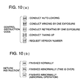
- Figs. 10(a) and 10(b) show carrier's control instruction codes and carrier's return instruction.
- Both of the above-mentioned carrier control instruction codes and return instructions can be constituted using 4 bits.
- control code "AA”” represents an auto-loading execution instruction.
- BB represents winding by one exposure.
- CC represents instruction of retreating by one exposure.
- DD represents taking up executing instruction.
- EE represents a version number requesting instruction.
- "aa” represents “finished normally” information.
- “bb” represents “finished abnormally (time is over)” information and
- cc” represents finished abnormally (abnormal operation)”.
- the restore instruction code for example, "Q" is sent from the personal computer to the scanner.
- the scanner When receiving this instruction code, the scanner returns the return instruction "q" to the personal computer.
- communication between personal computer 60 and scanner 30 starts.
- communication between the personal computer and the film carrier, as control means becomes possible. Even when specifications are modified, it is not necessary to change the scanner.
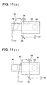
- a cartridge can be replaced while loading the carrier on the scanner.
- Figs. 11(a) and 11(b) are explanation drawings of cartridge replacement.
- cartridge 42 When an image is read by means of pre-scanning, as shown in Fig. 11(a), cartridge 42 is hidden inside scanner 30.
- ejecting as shown in Fig. 11(b), cartridge 42 is protruded from scanner 30 due to ejecting function.
- opening the lid of the cartridge section of carrier 40 under a status as shown in Fig. 11(b) cartridge 42 which has been loaded is removed and a new cartridge can be loaded.
- it is so convenient to replace cartridges while a film carrier is loaded to the scanner.
- the scanner section and the personal computer section were separated.
- the present invention is not limited thereto.
- the scanner section and the personal computer section may be integral.
- a photographic image processing apparatus can be provided which can effectively process an image when image information is read and displayed on the displaying means, if the type of film if an IX-240 long roll film.
Landscapes
- Engineering & Computer Science (AREA)
- Multimedia (AREA)
- Signal Processing (AREA)
- Facsimiles In General (AREA)
- Facsimile Scanning Arrangements (AREA)
- Holders For Sensitive Materials And Originals (AREA)
- Projection-Type Copiers In General (AREA)
Description
Claims (18)
- A film carrier (40) for use in a film scanner (30), comprising:(a) an aperture (38) for image reading;(b) a film conveying means for conveying a film on which image information has been recorded to form separated image frames to the aperture (38) one frame by one frame of the film; and(c) a communication means (54) for receiving a control signal to control the conveying means.
- The film carrier of claim 1 further comprising a film cartridge loading portion for loading a film cartridge housing the film.
- The film carrier of claim 2, wherein the film conveying means conveys the film from the film cartridge loaded in the film cartridge loading portion to the aperture (38) for image reading.
- The film carrier of claim 1 further comprising a driving force transmitting section for transporting the film carrier.
- The film carrier of claim 4, wherein the driving force transmitting section is a rack (41) provided on a main body of the film carrier.
- A film scanner comprising:(a) a film carrier according to any of claims 1 to 5 further comprising:(b) an image reading means (37) for optically reading the recorded image information on, the film; and(c) a first data communication section (4) connected with the communication means for outputting the control signal to the film carrier.
- The film scanner of claim 6 further comprising a moving means for moving the image reading means with respect to the film carrier.
- The film scanner of claim 1 further comprising a control means (1) for generating the control signal.
- The film scanner of claim 8, wherein the control means (1) generates a control signal to convey the film by one frame to the film carrier.
- The film scanner of claim 8, wherein the control means (1) controls the moving means so that the image reading means scans the film and reads image information for one frame of the film.
- The film scanner of claim 10 further comprising a second outputting means (4) for the image information of said one frame of the film to a host side.
- The film scanner of claim 6 further comprising a film carrier transporting means for transporting the film carrier.
- The film scanner of claim 12, wherein the film carrier transporting means transports the film carrier from a predetermined position at which image reading is conducted to an ejecting position.
- The film scanner of claim 13, wherein at the ejecting position a part of the film carrier is protruded outside the apparatus, and a film cartridge housing the film therein which is loaded inside the film carrier can be replaced.
- The film scanner of claim 6 further comprising an inputting means (4) for receiving the control signal from a host
- A method for reading an image on a film in an image reading apparatus including:a film scanner loaded with a film carrier according to any of claims 1 to 5, said film scanner further comprising a displaying means (24);and a control means (1) for controlling the film scanner and the displaying means, the method comprising the steps of:(a) generating the control signal in the control means;(b) communicating the control signal to the film carrier through the communication means;(c) conveying the film by one frame to the aperture (38) for image reading according to the control signal;(d) optically reading by an image reading means housed in the film scanner the image information recorded on the film conveyed to the aperture (38) for image reading; and(e) displaying the image information on the displaying means.
- The method of claim 16 further comprising the step of adjusting a white balance by reading an irradiated light emitted from a light source by the image reading means, before the step of conveying the film to the aperture (38).
- The method of claim 16, wherein the step of the reading includes reading continuously the film and the step of the displaying includes index-displaying the image information continuously read for a plurality of frames onto the displaying means.
Applications Claiming Priority (3)
| Application Number | Priority Date | Filing Date | Title |
|---|---|---|---|
| JP10527696 | 1996-04-25 | ||
| JP10527696A JP3630495B2 (en) | 1996-04-25 | 1996-04-25 | Photo image processing device |
| JP105276/96 | 1996-04-25 |
Publications (3)
| Publication Number | Publication Date |
|---|---|
| EP0804020A2 EP0804020A2 (en) | 1997-10-29 |
| EP0804020A3 EP0804020A3 (en) | 1999-01-13 |
| EP0804020B1 true EP0804020B1 (en) | 2004-10-13 |
Family
ID=14403156
Family Applications (1)
| Application Number | Title | Priority Date | Filing Date |
|---|---|---|---|
| EP97106302A Expired - Lifetime EP0804020B1 (en) | 1996-04-25 | 1997-04-16 | Photographic image processing apparatus |
Country Status (5)
| Country | Link |
|---|---|
| US (1) | US5757420A (en) |
| EP (1) | EP0804020B1 (en) |
| JP (1) | JP3630495B2 (en) |
| DE (1) | DE69731139T2 (en) |
| TW (1) | TW366435B (en) |
Families Citing this family (4)
| Publication number | Priority date | Publication date | Assignee | Title |
|---|---|---|---|---|
| JP3557294B2 (en) * | 1995-08-29 | 2004-08-25 | オリンパス株式会社 | Scanner device |
| JP3445438B2 (en) * | 1996-04-26 | 2003-09-08 | コニカ株式会社 | Photographic image display |
| FR2787667B1 (en) * | 1998-12-18 | 2001-02-16 | Eastman Kodak Co | VISUALIZATION OF PHOTOGRAPHS ON TELEVISION SCREEN USING A MAGNETOSCOPE |
| US20030002092A1 (en) * | 2001-06-28 | 2003-01-02 | Tecu Kirk Steven | System, method and adapter for scanning a roll of transparent media |
Family Cites Families (12)
| Publication number | Priority date | Publication date | Assignee | Title |
|---|---|---|---|---|
| BE775363R (en) * | 1971-04-23 | 1972-03-16 | Staar Dev Cy S A | SLIDE SUPPORT WITH ADDED SOUND RECORDINGS AND DEVICES ALLOWING SIMULTANEOUS VISION AND HEARING |
| US4656524A (en) * | 1985-12-23 | 1987-04-07 | Polaroid Corporation | Electronic imaging copier |
| US4858003A (en) * | 1988-01-12 | 1989-08-15 | Eastman Kodak Company | Mechanism for handling slides and film strips |
| US5371614A (en) * | 1989-11-01 | 1994-12-06 | Tokyo Electric Co., Ltd. | Image scanner for film |
| JP2964364B2 (en) * | 1990-09-14 | 1999-10-18 | 富士写真フイルム株式会社 | Film image input device |
| US5295204A (en) * | 1991-07-18 | 1994-03-15 | Eastman Kodak Company | Method for color balancing a computer input scanner incorporating multiple scanning modes |
| US5155586A (en) * | 1991-08-19 | 1992-10-13 | Sony Corporation Of America | Method and apparatus for flare correction |
| JPH05176275A (en) * | 1991-11-29 | 1993-07-13 | Minolta Camera Co Ltd | Film player |
| JP3371929B2 (en) * | 1994-08-25 | 2003-01-27 | 株式会社ニコン | Feeder for image input device |
| US5589953A (en) * | 1994-06-24 | 1996-12-31 | Nikon Corporation | Image input system having an auto-feeder including loading magazine and discharge magazine arranged side by side and method |
| US5486959A (en) * | 1994-07-12 | 1996-01-23 | Tai; David | Adapter mechanism for extracting and retracting video tape from miniature cassettes |
| JP3542175B2 (en) * | 1994-09-05 | 2004-07-14 | オリンパス株式会社 | Electronic film viewer device |
-
1996
- 1996-04-25 JP JP10527696A patent/JP3630495B2/en not_active Expired - Fee Related
-
1997
- 1997-04-12 TW TW086104718A patent/TW366435B/en active
- 1997-04-15 US US08/839,631 patent/US5757420A/en not_active Expired - Fee Related
- 1997-04-16 DE DE69731139T patent/DE69731139T2/en not_active Expired - Fee Related
- 1997-04-16 EP EP97106302A patent/EP0804020B1/en not_active Expired - Lifetime
Also Published As
| Publication number | Publication date |
|---|---|
| JP3630495B2 (en) | 2005-03-16 |
| EP0804020A2 (en) | 1997-10-29 |
| DE69731139T2 (en) | 2005-10-13 |
| EP0804020A3 (en) | 1999-01-13 |
| TW366435B (en) | 1999-08-11 |
| DE69731139D1 (en) | 2004-11-18 |
| US5757420A (en) | 1998-05-26 |
| JPH09292661A (en) | 1997-11-11 |
Similar Documents
| Publication | Publication Date | Title |
|---|---|---|
| EP0804013B1 (en) | Film scanner | |
| US6233059B1 (en) | Scanner device and control method thereof, and image input system | |
| US6195182B1 (en) | Scanner having a unit for identifying a type of film holding unit | |
| US5995204A (en) | Photographic image processing apparatus | |
| EP0804020B1 (en) | Photographic image processing apparatus | |
| US20010040704A1 (en) | Method, apparatus and computer program product for initializing image processing apparatus | |
| US6542262B1 (en) | Scanner device and control method thereof, and film feeding device | |
| WO1996025004A1 (en) | Picture reader | |
| JPH06233069A (en) | Equipment and method for digitalizing picture | |
| US6023347A (en) | Scanner for scanning photographic images | |
| US6862119B1 (en) | Image reading device | |
| JP3581516B2 (en) | Image processing apparatus and reading control method | |
| US5883729A (en) | Scanner device | |
| US6674553B1 (en) | Image reading apparatus and image processing system | |
| EP0830002A1 (en) | Image reader | |
| US20030189735A1 (en) | Film scanner | |
| JP3371929B2 (en) | Feeder for image input device | |
| JP2003248274A (en) | Image reader | |
| JP3423565B2 (en) | Scanner device and control method thereof | |
| JP2001211295A (en) | Image reading method and apparatus, and storage medium | |
| JP3487366B2 (en) | Feeder for image input device | |
| JPH09312733A (en) | Film scanner | |
| JP2001169096A (en) | Image reading method and apparatus, and storage medium | |
| JP2000151894A (en) | Image reading device | |
| JPH09284645A (en) | Image reading device |
Legal Events
| Date | Code | Title | Description |
|---|---|---|---|
| PUAI | Public reference made under article 153(3) epc to a published international application that has entered the european phase |
Free format text: ORIGINAL CODE: 0009012 |
|
| AK | Designated contracting states |
Kind code of ref document: A2 Designated state(s): DE FR GB |
|
| PUAL | Search report despatched |
Free format text: ORIGINAL CODE: 0009013 |
|
| AK | Designated contracting states |
Kind code of ref document: A3 Designated state(s): DE FR GB |
|
| 17P | Request for examination filed |
Effective date: 19990706 |
|
| 17Q | First examination report despatched |
Effective date: 20031006 |
|
| GRAP | Despatch of communication of intention to grant a patent |
Free format text: ORIGINAL CODE: EPIDOSNIGR1 |
|
| GRAS | Grant fee paid |
Free format text: ORIGINAL CODE: EPIDOSNIGR3 |
|
| GRAA | (expected) grant |
Free format text: ORIGINAL CODE: 0009210 |
|
| AK | Designated contracting states |
Kind code of ref document: B1 Designated state(s): DE FR GB |
|
| REG | Reference to a national code |
Ref country code: GB Ref legal event code: FG4D |
|
| REF | Corresponds to: |
Ref document number: 69731139 Country of ref document: DE Date of ref document: 20041118 Kind code of ref document: P |
|
| PGFP | Annual fee paid to national office [announced via postgrant information from national office to epo] |
Ref country code: GB Payment date: 20050413 Year of fee payment: 9 |
|
| PLBE | No opposition filed within time limit |
Free format text: ORIGINAL CODE: 0009261 |
|
| STAA | Information on the status of an ep patent application or granted ep patent |
Free format text: STATUS: NO OPPOSITION FILED WITHIN TIME LIMIT |
|
| ET | Fr: translation filed | ||
| 26N | No opposition filed |
Effective date: 20050714 |
|
| PGFP | Annual fee paid to national office [announced via postgrant information from national office to epo] |
Ref country code: FR Payment date: 20060410 Year of fee payment: 10 |
|
| PGFP | Annual fee paid to national office [announced via postgrant information from national office to epo] |
Ref country code: DE Payment date: 20060413 Year of fee payment: 10 |
|
| PG25 | Lapsed in a contracting state [announced via postgrant information from national office to epo] |
Ref country code: GB Free format text: LAPSE BECAUSE OF NON-PAYMENT OF DUE FEES Effective date: 20060416 |
|
| GBPC | Gb: european patent ceased through non-payment of renewal fee |
Effective date: 20060416 |
|
| PG25 | Lapsed in a contracting state [announced via postgrant information from national office to epo] |
Ref country code: DE Free format text: LAPSE BECAUSE OF NON-PAYMENT OF DUE FEES Effective date: 20071101 |
|
| PG25 | Lapsed in a contracting state [announced via postgrant information from national office to epo] |
Ref country code: FR Free format text: LAPSE BECAUSE OF NON-PAYMENT OF DUE FEES Effective date: 20070430 |