JP3623899B2 - Joint structure of concrete slab and steel web in composite box girder - Google Patents
Joint structure of concrete slab and steel web in composite box girder Download PDFInfo
- Publication number
- JP3623899B2 JP3623899B2 JP25846899A JP25846899A JP3623899B2 JP 3623899 B2 JP3623899 B2 JP 3623899B2 JP 25846899 A JP25846899 A JP 25846899A JP 25846899 A JP25846899 A JP 25846899A JP 3623899 B2 JP3623899 B2 JP 3623899B2
- Authority
- JP
- Japan
- Prior art keywords
- steel web
- concrete floor
- floor slab
- web
- composite box
- Prior art date
- Legal status (The legal status is an assumption and is not a legal conclusion. Google has not performed a legal analysis and makes no representation as to the accuracy of the status listed.)
- Expired - Fee Related
Links
Images


Description
【0001】
【発明の属する技術分野】
この発明は、複合箱桁におけるコンクリート床版と鋼製ウエブの接合構造に関する。
本発明の接合構造が採用される複合箱桁は、上下並行なコンクリート床版と両側の波形鋼製ウエブとで形成されているので、全体がコンクリートで製作されているプレストレスコンクリート箱桁よりも軽量に製作でき、また、波形鋼板の特性である長さ方向(桁軸方向)の低剛性を生かすことによってコンクリート床版に対するプレストレスの導入においては利便性があるなどの理由により、橋桁として利用されていることは周知のところである。このような複合箱桁は、土木分野の他、建築分野や機械分野等において比較的長尺の大型構造物として使用するに好適している。
【0002】
【従来の技術】
この種の複合箱桁における従来のコンクリート床版(コンクリートスラブ)と鋼製ウエブの接合構造としては、例えば従来例1として、特開平7−189425号公報等に示されたものを挙げることができる。
この接合構造は図21に示すように、両側の波形鋼製ウエブ12の上端面の桁軸方向にフランジプレート13を溶接すると共に、各フランジプレート13の外向き上面に多数の頭付きスタッド14を溶接し、更に、前記フランジプレート13及びスタッド部分にコンクリート床版15を接続させるようにして打設して成る。前記の頭付きスタッド14はコンクリート床版15に埋設され、また、フランジプレート13はコンクリート床版15の受け板として作用することになって、両側の波形鋼製ウエブ12とコンクリート床版15との接合が達成される。
【0003】
しかし、従来例1の接合構造においては、いくつかの問題点がある。
すなわち、一つには、波形鋼製ウエブ12の上端面にフランジプレート13を溶接するに際し、それらの接触部において波形をなす隅肉溶接を要するところから、溶接の自動化が困難であってコスト高となることである。他の一つは、複合箱桁合の桁軸方向にケーブルでプレストレスを導入する時、波形鋼製ウエブ12の特性である低剛性がフランジプレート13による抵抗により阻害され、コンクリート床版15に対する十分にして好ましい状態でのプレストレスの導入が難しくなることである。更に別の一つには、下段のコンクリート床版の打設時にその上面と下部フランジの下面との間の接触部にブリージング水が溜まりやすく、その部分に空洞ができることになって、コンクリート床版と下部フランジとの接合について不具合を生じることである。
【0004】
また、従来例2として図22に示す例がある。この従来例2では、両側の波形鋼製ウエブ12の上端面の桁軸方向に接合棒鋼16を溶接すると共に、両側の波形鋼製ウエブ12の上端部に多数の孔17を穿設し、それらの孔17に横方向の鉄筋18を挿通させて両ウエブ間に掛け渡し、前記の縦横の鉄筋及びウエブの上辺部分にコンクリートを打設してコンクリート床版を形成させたものを挙げることができる。
【0005】
しかし、従来例2の接合構造によれば、全体としての構成が複雑となるばかりか、波形鋼製ウエブ12の上端辺部がコンクリート床版に対し差し込まれた状態となっているので、長期の使用においては、ウエブの差込み部分を通じてコンクリート床版内に雨水が浸入し、ウエブの差込み部分自体や前記の接合用鉄筋を腐食させることとなって、コンクリート床版と波形鋼製ウエブとの接合強度を低下させることになるなどの問題点を有している。
【0006】
【発明が解決しようとする課題】
この発明に係る複合箱桁におけるコンクリート床版と鋼製ウエブの接合構造は、前述の問題点を悉く解決するために提案されたものである。すなわち、本発明においては、鋼製ウエブ、特に波形鋼製ウエブの上下端面に溶接されるフランジや波形鋼製ウエブがコンクリート床版にさし込まれた状態を排することにより、構成を簡単にして接合構造のコストダウンを図ると共に、波形鋼製ウエブの長さ方向(桁軸方向)の低剛性が阻害されることをなくし、複合箱桁、すなわちコンクリート床版に対する桁軸方向のプレストレスの導入において十分なプレストレス量が得られるようにすることを目的とする。
【0007】
また、コンクリート打設時のブリージング水による空洞の発生をなくしてコンクリートの充填における信頼性を向上させるようにし、更には、コンクリート床版と波形鋼製ウエブとの差し込み部の腐食を排すことにより、接合強度の安定性が十分に高められるようにすることを目的としている。
【0008】
【課題を解決するための手段】
上記の目的を達成するため、この発明に係る請求項1の複合箱桁におけるコンクリート床版と鋼製ウエブの接合構造は、上下並行なコンクリート床版と両側の鋼製ウエブとからなるプレストレス導入方式の複合箱桁において、各鋼製ウエブの上下辺部の内側面又は外側面に横方向に向け多数の連結部材を突設し、上下のコンクリート床版は両側の鋼製ウエブの上下辺部の内側面又は外側面に対し前記連結部材を介して接合したことを特徴とする。
また、請求項2の発明は、請求項1記載の接合構造において、鋼製ウエブを波形鋼板で構成したことを特徴とする。
また、請求項3の発明は、請求項1、2記載の接合構造において、鋼製ウエブに突設する連結部材を棒体とし、それらをコンクリート床版に埋設することにより、コンクリート床版と鋼製ウエブとを接合したことを特徴とする。
更に、請求項4の発明は、請求項1、2記載の接合構造において、鋼製ウエブに突設する連結部材を板体とし、それらをコンクリート床版に埋設することにより、コンクリート床版と鋼製ウエブとを接合したことを特徴とする。
【0009】
更にまた、請求項5の発明は、請求項3記載の接合構造において、鋼製ウエブに突設する連結部材を板体とし、それらの板体を波形鋼製ウエブの取付面に、該波形鋼製ウエブの谷部又における稜に対し傾斜させるようにして設けたことを特徴とする。
加えて、請求項6の発明は、請求項1乃至5記載の接合構造において、連結部材を孔開き板体としたことを特徴とする。
【0010】
【発明の実施の形態】
以下、この発明の接合構造を、図面に示す5例の実施形態に基づいて詳述する。
図1及び図2はこの発明の第1実施形態を、図3及び図4は第2実施形態を、図5及び図6は第3実施形態を、図7は第4実施形態を、図8は第5実施形態をそれぞれ示している。第2実施形態〜第5実施形態において、第1実施形態と同一の符号で示す部材ないし部位はそれぞれ相互にほぼ同等な作用を呈するので、それらについては重複説明を避け、主として第1実施形態の接合構造を代表させて説明する。
【0011】
橋桁等として採用されるプレストレス方式の複合箱桁は、周知の通り、上下並行な鉄筋コンクリート製のコンクリート床版1,2と両側の波形鋼製ウエブ3,3とで中空に形成されるものであって、上下段のコンクリート床版1,2(コンクリートスラブ)には、それらコンクリート床版1,2の桁軸方向に埋設させた内ケーブル又は内棒鋼(図示しない)及び箱桁の中空部4を桁軸方向に挿通させた外ケーブル又は外棒鋼(図示しない)等により、プレストレスが導入付加される。
【0012】
なお、複合箱桁には、桁軸方向の端部に横桁部が、また、桁軸方向の中間部に隔壁が設けられるのが普通であるが、図面においてはそれらの記入は省略してある。
【0013】
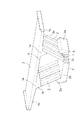
図1及び図2に示すこの発明の第1実施形態においては、各波形鋼製ウエブ3の上下辺部3a,3bにおける内側面に横方向に向け多数の鋼製の連結部材5としての頭付きスタッド等の棒体が溶接等により突設させてある。そして、前記の棒体5を上下のコンクリート床版1,2の所定の部分に埋設させることにより、上下のコンクリート床版1,2と両側の鋼製ウエブ3,3の上下辺部3a,3bにおける内側面とを接合させ、複合箱桁が構成される。前記複合箱桁において、両側の鋼製ウエブ3は逆八の字状をなすように傾斜させて組み付けてある。
【0014】
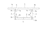
更に具体的には、上段のコンクリート床版1には本体部分から下方に一体に突設した左右一対の接合凸部1a,1bが設けてあって、各接合凸部1aの外側面が各鋼製ウエブ3の上辺部3aの内側面に対し棒状である連結部材5を介して離脱不能に接合され、また、下段のコンクリート床版2における桁軸直角方向の各側端面が各鋼製ウエブ3の下辺部3bの内側面に対し棒体である連結部材5を介して離脱不能に接合されている。
【0015】
図1及び図2において、符号1b,1bは上段のコンクリート床版1の両側辺を幅方向に張り出した張出し部、6はコンクリート床版1,2に埋設された鉄筋である。
【0016】
次に、図4の第2実施形態について説明する。第2実施形態においては、多数の頭付きスタッドのような棒体5は、いずれも各鋼製ウエブ3の上下辺部3a,3bの外側面に溶接等により突設させてある。そして、鋼製ウエブ3の上辺部3aは上段コンクリート床版1の接合凸部1aの内側面に当接してあり、鋼製ウエブ3の下辺部3bは下段コンクリート床版2の両側辺部に一体に突設したハンチ部2a,2aのそれぞれの内側面に当接してある点が第1実施形態のものとは相違している。
【0017】
但し、コンクリート床版1,2と鋼製ウエブ3,3との接合部において、鋼製ウエブ3の側面に突設された連結部材としての棒体5の突出部分がコンクリート床版1,2の所定の部位(1a,2a)に埋設され、その結合を強固なものとしていることは第1実施形態と変わりはない。
【0018】
また、図5及び図6の第3実施形態の接合構造においては、棒体5は各鋼製ウエブ3の上辺部3aについては、該ウエブ3の内側面に突設してあり、また、各鋼製ウエブ3の下辺部3bのものについては該ウエブ3の外側面に突設してある。そして、鋼製ウエブ3の上辺部3aは上段コンクリート床版1の接合凸部1aの外側面に当接してあり、鋼製ウエブ3の下辺部3bは下段コンクリート床版2のハンチ部2aの内角面に当接してある点が第1実施形態のものとは相違している。
【0019】
但し、コンクリート床版1,2と鋼製ウエブ3,3との接合部において、鋼製ウエブ3の側面に突設された連結部材としての棒体5の突出部分がコンクリート床版1,2の所定部位(1a,2a)に埋設され、その結合を強固なものとしていることは第1実施形態と変わりはない。
【0020】
図7に示す第4実施形態は、図1及び図2の第1実施形態の変形例である。この例において、両側の波形鋼製ウエブ3,3はいずれも鉛直をなすように組み付けられ、また、下段コンクリート床版2にハンチ部2a,2aが設けられている点を除けば、他の構成は第1実施形態のものとほぼ同等である。
【0021】
図8に示す第5実施形態は、図3及び図4の第2実施形態の変形例であって、両側の波形鋼製ウエブ3,3はいずれも鉛直をなすように組み付けられている。他の構成は第2実施形態のものとほぼ同等である。
【0022】
鋼製ウエブ3の上下辺部3a,3bにおける内側面又は外側面に横方向に向け、溶接等で突設される多数の連結部材5としては、上述のような頭付きスタッド(図9参照)その他の棒体、平板体、孔開き平板体(図10及び図11参照)及び/又はアングル材を切断したL字状の板片等の小部片を利用することができる。
【0023】
前記の連結部材5が棒状であるものは、鋼製ウエブ3の取付面に対し直角をなすようにして固設するのが普通であるが、突出軸線を傾斜させて固設することもできる。また、前記の連結部材5を板体としたものは、図10又は図11に示すように波形鋼製ウエブ3の山部の稜3cに対し直角又は平行をなすようにして設けることもできるし、図12に示すように山部の稜3cに対し傾斜させて設けることもできる。
【0024】
要するに、連結部材5は同じ形状の小部片であっても、鋼製ウエブ3の取付面に対し取付けの向きを変えたり孔を穿設するなどの工夫により、コンクリート床版1,2に対する埋設において、固着具合(接合具合)を強化することができる。
【0025】
なお、図13及び図14は、本発明の比較参考例を示す図で、同図において、符号50は、コンクリート床版1,2に対し受け板としての作用を呈する連結部材(棒体)である。
【0026】
また図15〜図18は、第1実施形態の接合構造についての施工工程の概略を例示したものである。その工程を順を追って説明すると、以下の通りである。
(1)第1工程(図15参照)
連結部材5を内側面に突設した両側の波形鋼製ウエブ3,3をウエブ支保工8で支持させつつ下型枠9上に設置し、下段コンクリート床版(スラブ)2の配筋6を行う。
(2)第2工程(図16参照)
下段コンクリート床版2を打設し養生する。
【0027】
(3)第3工程(図17参照)
上段コンクリート床版(スラブ)1用の上型枠11を型枠支保工10で支持させつつ波形鋼製ウエブ3,3上に設置し、上段コンクリート床版1の配筋6を行う。
(4)第4工程(図18参照)
上段コンクリート床版1を打設し養生する。これをもって接合構造(複合箱桁の組立)が完成する。
なお、上記のウエブ支保工8、型枠支保工10、下型枠9及び上型枠11は適宜解体、撤去することは言うまでもない。
【0028】
また、図19及び図20は、第2実施形態の接合構造についての施工工程における前半の手順の概略を例示したものである。
(1)第1工程(図19)
下型枠9内に下段コンクリート床版(スラブ)2の配筋6を行い、下段コンクリート床版2の本体部を打設し養生する。次いで、連結部材5を内側面に突設した両側の波形鋼製ウエブ3,3をウエブ支保工8で支持させつつ前記下段コンクリート床版2の本体部上に設置する。
(2)第2工程(図20)
下段コンクリート床版2のハンチ部2aについてコンクリートを打設し養生する。
【0029】
(3)第3工程以後の後半の手順に関しては、上述した第1実施形態の施工工程における第3工程(図17参照)及び、第4工程(図18参照)と同じであるから、その図示並びに説明は省略する。
【0030】
なお、実施条件が許せば、波形鋼板に代えて平鋼板を用いて本発明を実施できる。
【0031】
【発明の効果】
以上に説明したこの発明の複合箱桁におけるコンクリート床版と鋼製ウエブの接合構造によれば、従来の接合構造で採用されていた、波形鋼製ウエブの上下端に溶接されたスタッド突設用のフランジや接合部に縦横に配された鉄筋は備えられておらず、上下のコンクリート床版と両側の波形鋼製ウエブとの間を強固に結合するための小部片から成る連結部材は、各鋼製ウエブの上下辺部における内外側面に横向きに突設してあって、コンクリート床版の接合部は連結部材が突設された鋼製ウエブの上下辺部に当接させるようにしてあるので、次に示すような効果を奏する。
【0032】
1.接合構造はその構成が簡単で、安価に提供できる。
2.接合用のフランジや縦鉄筋を備えていないので、波形鋼製ウエブの桁軸方向の低剛性が全く阻害されることがなく、コンクリート床版に対するプレストレスの導入において十分なプレストレスを付与できる。
【0033】
3.コンクリート打設時にブリージング水による空洞の発生がなく、床版コンクリートの充填において充填の信頼性が向上する。
4.コンクリート床版と波形鋼製ウエブとの接合強度の安定性を向上させることができる。
【図面の簡単な説明】
【図1】この発明の第1実施形態の接合構造を実施した複合箱桁を一部切除して示す概略部分斜視図。(なお、図2以下の各図は図1同様いずれも概略的に示してある。)
【図2】(A)はその横断正面図、(B)は図2(A)におけるIIB部の拡大図、(C)は図2(A)におけるIIC部の拡大図、(D)は図2(C)のIID−IID線による拡大部分断面図。
【図3】この発明の第1実施形態の接合構造を実施した複合箱桁を一部切除して示す部分斜視図。
【図4】(A)はその横断正面図、(B)は図4(A)におけるIVB部の拡大図、(C)は図2(A)におけるIVC部の拡大図、(D)は図4(C)のIVD−IVD線による拡大部分断面図。
【図5】この発明の第3実施形態の接合構造を実施した複合箱桁を一部切除して示す部分斜視図。
【図6】(A)はその横断正面図、(B)は図6(A)におけるVIB部の拡大図、(C)は図6(A)におけるVI(C)部の拡大図、(D)は図6(C)のVID−VID線による拡大部分断面図。
【図7】この発明の第4実施形態の接合構造を実施した複合箱桁を示す縦断正面図。
【図8】この発明の第5実施形態の接合構造を実施した複合箱桁を示す縦断正面図。
【図9】波形鋼製ウエブの上辺部の側面に対し連結部材として頭付きスタッドを突設した例を示す部分斜視図。
【図10】波形鋼製ウエブの上辺部側面に対し連結部材として孔開き板体を突設した例を示す部分斜視図。
【図11】波形鋼製ウエブの上辺部側面に対し連結部材として孔開き板体を突設した別の例を示す部分斜視図。
【図12】波形鋼製ウエブの上辺部側面に対し連結部材として孔開き板体を突設した更に別の例を示す部分斜視図。
【図13】本発明の比較参考例を示す図で、(A)は複合箱桁の一部を切除して示す部分側面図、(B)は正面図。
【図14】図13の複合箱桁から取り外した波形鋼製ウエブ及びそのウエブの上下辺部の側面に突設された板体(連結部材)の拡大部分斜視図。
【図15】第1実施形態の接合構造(図1及び図2参照)についての施工工程における第1工程を示す正面図。
【図16】その第2工程の正面図。
【図17】その第3工程の正面図。
【図18】その第4工程の正面図。
【図19】第2実施形態の接合構造(図4参照)についての施工工程における第1工程を示す正面図。
【図20】その第2工程の正面図。
【図21】(A)、(B)は、従来例1の断面図と詳細部斜視図である。
【図22】(A)、(B)は、従来例2の断面図と詳細部斜視図である。
【符号の説明】
1 上段のコンクリート床版
1a 接合凸部
1b 張出し部
2 下段のコンクリート床版
2a ハンチ部
3 波形鋼製ウエブ
3a 上辺部
3b 下辺部
3c 稜
3d 谷部
4 中空部
5 連結部材(棒体)
50 連結部材
6 鉄筋(配筋)
7 嵌込み凹部
8 ウエブ支保工
9 下型枠
10 型枠支保工
11 上型枠
12 波形鋼板ウエブ
13 フランジプレート
14 頭付きスタッド
15 コンクリート床版
16 接合棒鋼
17 孔
18 横鉄筋[0001]
BACKGROUND OF THE INVENTION
The present invention relates to a joint structure of a concrete floor slab and a steel web in a composite box girder.
The composite box girder in which the joint structure of the present invention is adopted is formed of a concrete floor slab parallel to upper and lower sides and corrugated steel webs on both sides, so that it is more than a prestressed concrete box girder made entirely of concrete. It can be manufactured lightweight, and it can be used as a bridge girder for the convenience of prestressing for concrete floor slabs by taking advantage of the low rigidity in the length direction (girder axis direction), which is a characteristic of corrugated steel sheets. This is well known. Such a composite box girder is suitable for use as a comparatively long large structure in the field of construction, machinery, etc. in addition to the civil engineering field.
[0002]
[Prior art]
As a conventional joint structure of a concrete floor slab (concrete slab) and a steel web in this type of composite box girder, for example, the one shown in Japanese Patent Laid-Open No. 7-189425 can be cited as a conventional example 1. .
As shown in FIG. 21 , this joining structure welds the
[0003]
However, the joint structure of Conventional Example 1 has several problems.
That is, when the
[0004]
Further, there is an example shown in FIG. 22 as a conventional example 2. In this conventional example 2, the
[0005]
However, according to the joint structure of Conventional Example 2, not only the overall configuration becomes complicated, but also the upper end side of the
[0006]
[Problems to be solved by the invention]
The joint structure of a concrete floor slab and a steel web in the composite box girder according to the present invention has been proposed to solve the above-mentioned problems. That is, in the present invention, the structure is simplified by eliminating the state in which the flange welded to the upper and lower end surfaces of the steel web, particularly the corrugated steel web, and the corrugated steel web are inserted into the concrete floor slab. As a result, the cost of the joint structure is reduced and the low rigidity of the corrugated steel web in the length direction (girder axis direction) is not obstructed. The purpose is to obtain a sufficient amount of prestress in the introduction.
[0007]
In addition, by eliminating the generation of cavities due to breathing water when placing concrete, the reliability of filling concrete is improved, and furthermore, by eliminating the corrosion of the insertion part between the concrete floor slab and the corrugated steel web. The purpose is to sufficiently improve the stability of the bonding strength.
[0008]
[Means for Solving the Problems]
In order to achieve the above object, the joint structure of a concrete floor slab and a steel web in the composite box girder according to
According to a second aspect of the present invention, in the joining structure according to the first aspect, the steel web is formed of a corrugated steel sheet.
According to a third aspect of the present invention, there is provided a joint structure according to the first or second aspect, wherein the connecting member protruding from the steel web is used as a rod and is embedded in the concrete floor slab so that the concrete floor slab and the steel It is characterized in that it is bonded to a web.
Furthermore, the invention according to
[0009]
Furthermore, the invention according to
In addition, the invention of
[0010]
DETAILED DESCRIPTION OF THE INVENTION
Hereinafter, the joining structure of the present invention will be described in detail based on five embodiments shown in the drawings.
1 and 2 show the first embodiment of the present invention, FIGS. 3 and 4 show the second embodiment, FIGS. 5 and 6 show the third embodiment, FIG. 7 shows the fourth embodiment, and FIG. Respectively show the fifth embodiment. In the second to fifth embodiments, members or parts indicated by the same reference numerals as those in the first embodiment each exhibit substantially the same action, so that they are not redundantly described and are mainly used in the first embodiment. The junction structure will be described as a representative .
[0011]
As is well known, a prestressed composite box girder adopted as a bridge girder, etc., is formed of a hollow reinforced concrete
[0012]
It should be noted that a composite box girder usually has a horizontal girder portion at the end in the girder axis direction and a partition wall at the middle portion in the girder axis direction, but these are omitted in the drawing. is there.
[0013]
In the first embodiment of the present invention shown in FIG. 1 and FIG. 2, heads as a large number of
[0014]
More specifically, the upper
[0015]
In FIGS. 1 and 2,
[0016]
Next , a second embodiment of FIG. 4 will be described. In the second embodiment, a large number of
[0017]
However, at the joint between the
[0018]
Further, in the joining structure of the third embodiment shown in FIGS. 5 and 6, the
[0019]
However, at the joint between the
[0020]
The fourth embodiment shown in FIG. 7 is a modification of the first embodiment shown in FIGS. In this example, the
[0021]
The fifth embodiment shown in FIG. 8 is a modification of the second embodiment of FIGS. 3 and 4, and the
[0022]
As a large number of connecting
[0023]
The connecting
[0024]
In short, even if the connecting
[0025]
13 and 14 are diagrams showing comparative reference examples of the present invention. In the figure,
[0026]
The FIGS. 15 to 18 are an illustration of a schematic construction steps for joining structure of the first embodiment. The steps will be described in order as follows.
(1) First step (see FIG. 15)
The
(2) Second step (see FIG. 16)
Place and cure the lower
[0027]
(3) Third step (see FIG. 17)
The
(4) Fourth step (see FIG. 18)
Place the upper
Needless to say, the
[0028]
Moreover, FIG.19 and FIG.20 illustrates the outline of the procedure of the first half in the construction process about the joining structure of 2nd Embodiment.
(1) First step (FIG. 19)
(2) Second step (FIG. 20)
Concrete is cast and cured on the
[0029]
(3) Since the latter half of the procedure after the third step is the same as the third step (see FIG. 17) and the fourth step (see FIG. 18) in the construction step of the first embodiment described above, its illustration The description is omitted.
[0030]
If the implementation conditions permit, the present invention can be implemented using flat steel plates instead of corrugated steel plates.
[0031]
【The invention's effect】
According to the joint structure of the concrete floor slab and the steel web in the composite box girder of the present invention described above, the stud projectingly welded to the upper and lower ends of the corrugated steel web, which has been adopted in the conventional joint structure. There are no reinforcing bars arranged vertically and horizontally on the flanges and joints, and the connecting member consisting of small pieces for firmly connecting the upper and lower concrete floor slabs and the corrugated steel webs on both sides, The steel web is projected sideways on the inner and outer sides of the upper and lower sides of each steel web, and the joint portion of the concrete slab is made to contact the upper and lower sides of the steel web on which the connecting member is projected. Therefore, the following effects are achieved.
[0032]
1. The structure of the joining structure is simple and can be provided at low cost.
2. Since no joining flange or vertical reinforcing bar is provided, the low rigidity of the corrugated steel web in the spar axis direction is not hindered at all, and sufficient prestress can be imparted in the introduction of prestress to the concrete slab.
[0033]
3. There is no generation of cavities due to breathing water when placing concrete, and the filling reliability is improved in filling floor slab concrete.
4). The stability of the joint strength between the concrete slab and the corrugated steel web can be improved.
[Brief description of the drawings]
FIG. 1 is a schematic partial perspective view showing a composite box girder in which a joining structure according to a first embodiment of the present invention is partially cut away. (In addition, each figure after FIG. 2 is schematically shown as in FIG. 1.)
2A is a cross-sectional front view thereof, FIG. 2B is an enlarged view of the IIB portion in FIG. 2A, FIG. 2C is an enlarged view of the IIC portion in FIG. 2A, and FIG. The expanded partial sectional view by the IID-IID line | wire of 2 (C).
FIG. 3 is a partial perspective view showing a part of the composite box girder in which the joining structure according to the first embodiment of the present invention is implemented.
4A is a cross-sectional front view thereof, FIG. 4B is an enlarged view of the IVB portion in FIG. 4A, FIG. 4C is an enlarged view of the IVC portion in FIG. 2A, and FIG. The expanded partial sectional view by the IVD-IVD line of 4 (C).
FIG. 5 is a partial perspective view showing a composite box girder in which a joining structure according to a third embodiment of the present invention is partially cut away.
6A is a cross-sectional front view thereof, FIG. 6B is an enlarged view of a VIB portion in FIG. 6A, FIG. 6C is an enlarged view of a VI (C) portion in FIG. ) Is an enlarged partial cross-sectional view taken along the line VID-VID in FIG.
FIG. 7 is a longitudinal front view showing a composite box girder in which a joining structure according to a fourth embodiment of the present invention is implemented.
FIG. 8 is a longitudinal front view showing a composite box girder in which a joining structure according to a fifth embodiment of the present invention is implemented.
FIG. 9 is a partial perspective view showing an example in which a headed stud is provided as a connecting member on the side surface of the upper side of the corrugated steel web.
FIG. 10 is a partial perspective view showing an example in which a perforated plate body is provided as a connecting member on the upper side surface of the corrugated steel web.
FIG. 11 is a partial perspective view showing another example in which a perforated plate body is projected as a connecting member on the upper side surface of the corrugated steel web.
FIG. 12 is a partial perspective view showing still another example in which a perforated plate body is projected as a connecting member on the upper side surface of the corrugated steel web.
13A and 13B are diagrams showing a comparative reference example of the present invention, in which FIG. 13A is a partial side view showing a part of a composite box girder, and FIG. 13B is a front view.
14 is an enlarged partial perspective view of a corrugated steel web removed from the composite box girder of FIG . 13 and a plate (connecting member) projecting from the side surfaces of the upper and lower sides of the web.
FIG. 15 is a front view showing a first step in a construction step for the joint structure according to the first embodiment (see FIGS. 1 and 2).
FIG. 16 is a front view of the second step.
FIG. 17 is a front view of the third step.
FIG. 18 is a front view of the fourth step.
FIG. 19 is a front view showing a first step in a construction step for the joint structure (see FIG. 4) of the second embodiment.
FIG. 20 is a front view of the second step.
FIGS. 21A and 21B are a cross-sectional view and a detailed perspective view of a conventional example 1, respectively.
22A and 22B are a cross-sectional view and a detailed perspective view of a conventional example 2, respectively.
[Explanation of symbols]
DESCRIPTION OF
50 Connecting
7
Claims (6)
Priority Applications (1)
| Application Number | Priority Date | Filing Date | Title |
|---|---|---|---|
| JP25846899A JP3623899B2 (en) | 1999-09-13 | 1999-09-13 | Joint structure of concrete slab and steel web in composite box girder |
Applications Claiming Priority (1)
| Application Number | Priority Date | Filing Date | Title |
|---|---|---|---|
| JP25846899A JP3623899B2 (en) | 1999-09-13 | 1999-09-13 | Joint structure of concrete slab and steel web in composite box girder |
Publications (2)
| Publication Number | Publication Date |
|---|---|
| JP2001081720A JP2001081720A (en) | 2001-03-27 |
| JP3623899B2 true JP3623899B2 (en) | 2005-02-23 |
Family
ID=17320657
Family Applications (1)
| Application Number | Title | Priority Date | Filing Date |
|---|---|---|---|
| JP25846899A Expired - Fee Related JP3623899B2 (en) | 1999-09-13 | 1999-09-13 | Joint structure of concrete slab and steel web in composite box girder |
Country Status (1)
| Country | Link |
|---|---|
| JP (1) | JP3623899B2 (en) |
Cited By (4)
| Publication number | Priority date | Publication date | Assignee | Title |
|---|---|---|---|---|
| CN106087713A (en) * | 2016-08-25 | 2016-11-09 | 中铁五局集团路桥工程有限责任公司 | Stiff skeleton is locked outside a kind of assembled closure section |
| CN106758857A (en) * | 2017-03-09 | 2017-05-31 | 河南省交通规划设计研究院股份有限公司 | The construction method of precast block formula secondary prestress Wavelike steel webplate combination beam |
| CN106758856A (en) * | 2017-03-09 | 2017-05-31 | 河南省交通规划设计研究院股份有限公司 | The construction method of the pretensioned prestressing corrugated steel web plate composite box girder of precast block |
| CN106906749A (en) * | 2017-03-09 | 2017-06-30 | 河南省交通规划设计研究院股份有限公司 | The construction method of full assembled steel-concrete combined structure box beam |
Families Citing this family (21)
| Publication number | Priority date | Publication date | Assignee | Title |
|---|---|---|---|---|
| KR20010079453A (en) * | 2001-07-20 | 2001-08-22 | 이광민 | Bridge construction method using precast panel |
| JP2006265976A (en) * | 2005-03-25 | 2006-10-05 | Oriental Construction Co Ltd | Corrugated steel-plate web u component bridge and its construction method |
| CN1320210C (en) * | 2005-04-06 | 2007-06-06 | 湖南大学 | Steel-concrete combination backbone beam with big cantilever corrugated steel web overhanging beam |
| JP4644146B2 (en) * | 2006-03-07 | 2011-03-02 | 株式会社ピーエス三菱 | PC box girder bridge |
| JP2008240429A (en) * | 2007-03-28 | 2008-10-09 | Mitsui Eng & Shipbuild Co Ltd | Pc floor panel box girder bridge |
| JP2010163790A (en) * | 2009-01-15 | 2010-07-29 | Ps Mitsubishi Construction Co Ltd | Prestressed concrete box girder with struts |
| CN101798794B (en) * | 2010-03-29 | 2012-07-25 | 广东省公路勘察规划设计院股份有限公司 | Composite box girder bridge erected in advance by using corrugated steel web steel girders and construction method thereof |
| CN102733308B (en) * | 2012-06-19 | 2014-03-26 | 中铁八局集团昆明铁路建设有限公司 | Method for connecting steel guide girder with box girder |
| CN102953320A (en) * | 2012-12-10 | 2013-03-06 | 江苏省交通科学研究院股份有限公司 | Box bridge girder |
| CN103422619B (en) * | 2013-07-18 | 2016-01-27 | 浙江中隧桥波形钢腹板有限公司 | Combining structure microwave shrinkage type connection structure and construction technology |
| CN103422427B (en) * | 2013-07-18 | 2016-02-24 | 浙江中隧桥波形钢腹板有限公司 | Oblique hole flanging formula frange plate combining structure connecting key |
| CN103758020A (en) * | 2013-12-25 | 2014-04-30 | 广西科技大学 | Preparation technology for corrugated steel web combined box girder |
| CN104032669A (en) * | 2014-06-03 | 2014-09-10 | 南京工业大学 | Bridge box type girder of interlayer structure |
| CN104088232B (en) * | 2014-07-09 | 2016-06-01 | 北京交通大学 | A kind of emergency first-aid repair method of concrete box girder |
| CN104389262B (en) * | 2014-11-13 | 2016-05-18 | 北京东方园林股份有限公司 | A kind of Novel wooden plank road structure based on ecoscape |
| CN105603866A (en) * | 2016-02-19 | 2016-05-25 | 任自放 | Special-shaped steel plate combined structure box girder |
| CN108277744B (en) * | 2018-01-19 | 2019-11-15 | 郑州市交通规划勘察设计研究院 | Arch steel concrete combined bridge deck and its construction method |
| CN110747743A (en) * | 2019-09-27 | 2020-02-04 | 中交二航局第四工程有限公司安徽混凝土装配化构件分公司 | Steel-concrete bridge body pouring construction process |
| CN111305040A (en) * | 2020-02-28 | 2020-06-19 | 广东省交通规划设计研究院股份有限公司 | Cable-stayed bridge combined box girder adopting corrugated steel plate as diaphragm plate |
| CN113062197B (en) * | 2021-03-31 | 2022-08-23 | 浙江师范大学 | Assembly type stiffening large cantilever corrugated steel web PC combined box girder and construction method thereof |
| CN114438868B (en) * | 2022-01-06 | 2022-12-06 | 广东省冶金建筑设计研究院有限公司 | Corrugated steel web plate combined box girder and construction method thereof |
-
1999
- 1999-09-13 JP JP25846899A patent/JP3623899B2/en not_active Expired - Fee Related
Cited By (6)
| Publication number | Priority date | Publication date | Assignee | Title |
|---|---|---|---|---|
| CN106087713A (en) * | 2016-08-25 | 2016-11-09 | 中铁五局集团路桥工程有限责任公司 | Stiff skeleton is locked outside a kind of assembled closure section |
| CN106087713B (en) * | 2016-08-25 | 2018-06-22 | 中铁五局集团路桥工程有限责任公司 | Stiff skeleton is locked outside a kind of assembled closure section |
| CN106758857A (en) * | 2017-03-09 | 2017-05-31 | 河南省交通规划设计研究院股份有限公司 | The construction method of precast block formula secondary prestress Wavelike steel webplate combination beam |
| CN106758856A (en) * | 2017-03-09 | 2017-05-31 | 河南省交通规划设计研究院股份有限公司 | The construction method of the pretensioned prestressing corrugated steel web plate composite box girder of precast block |
| CN106906749A (en) * | 2017-03-09 | 2017-06-30 | 河南省交通规划设计研究院股份有限公司 | The construction method of full assembled steel-concrete combined structure box beam |
| CN106758856B (en) * | 2017-03-09 | 2018-07-24 | 河南省交通规划设计研究院股份有限公司 | The construction method of the pretensioned prestressing corrugated steel web plate composite box girder of precast block |
Also Published As
| Publication number | Publication date |
|---|---|
| JP2001081720A (en) | 2001-03-27 |
Similar Documents
| Publication | Publication Date | Title |
|---|---|---|
| JP3623899B2 (en) | Joint structure of concrete slab and steel web in composite box girder | |
| JP4347500B2 (en) | Bridge girder | |
| KR20140090816A (en) | An assembly type beam mold | |
| JP2006316580A (en) | Corrugated steel plate web pc composite beam and construction method of bridge using corrugated steel plate web pc composite beam | |
| JP2001027005A (en) | Connection structure of steel member and concrete in a composite structure | |
| JP2742989B2 (en) | Assembled rebar truss and manufacturing method thereof | |
| JP3410368B2 (en) | Connection method of corrugated steel web girder | |
| JP3881135B2 (en) | Connecting structure of floor slabs using concrete truss with concrete slab in bridge girder | |
| JP2004324211A (en) | Joint structure of precast concrete floor slab | |
| JP4101397B2 (en) | Method of joining concrete slab and corrugated steel in corrugated steel web bridge | |
| KR101583401B1 (en) | The continuous hybrid girder consist of concrete block and steel block which is can add prestress by gap difference between top and bottom of connection face of blocks | |
| JP3208530B2 (en) | Precast concrete formwork and structure using the same | |
| JP4340947B2 (en) | Composite beam structure | |
| JP3160777B2 (en) | End joining method and structure of precast concrete beam attached to precast concrete beam | |
| JP2004285823A (en) | Floor slab bridge and floor slab unit | |
| JP2958852B2 (en) | Steel concrete composite plate | |
| KR101724122B1 (en) | Prestressed concrete girder having reinforcing member and the construction method thereof | |
| JP2627707B2 (en) | Joint structure between underground continuous wall and underground skeleton | |
| KR102473696B1 (en) | Bridge having composite girdir and steel girdir | |
| JP2725572B2 (en) | Small beam construction method in reinforced concrete construction | |
| KR100496196B1 (en) | Composite Beam Stiffened with Prestressed Concrete Panel having Novel Connecting Structure and Connecting Assembly therefor | |
| KR102407736B1 (en) | Composite girdir reinforced by under flange of steel i-beam and construction method thereof | |
| JPS5910441B2 (en) | Fixing method for floor slabs | |
| JPH0452279Y2 (en) | ||
| JP5114258B2 (en) | Steel framework structure of steel concrete composite slab and method for producing steel framework structure |
Legal Events
| Date | Code | Title | Description |
|---|---|---|---|
| A977 | Report on retrieval |
Free format text: JAPANESE INTERMEDIATE CODE: A971007 Effective date: 20040301 |
|
| A131 | Notification of reasons for refusal |
Free format text: JAPANESE INTERMEDIATE CODE: A131 Effective date: 20040309 |
|
| A521 | Written amendment |
Free format text: JAPANESE INTERMEDIATE CODE: A523 Effective date: 20040507 |
|
| TRDD | Decision of grant or rejection written | ||
| A01 | Written decision to grant a patent or to grant a registration (utility model) |
Free format text: JAPANESE INTERMEDIATE CODE: A01 Effective date: 20041116 |
|
| A61 | First payment of annual fees (during grant procedure) |
Free format text: JAPANESE INTERMEDIATE CODE: A61 Effective date: 20041126 |
|
| S111 | Request for change of ownership or part of ownership |
Free format text: JAPANESE INTERMEDIATE CODE: R313122 |
|
| R371 | Transfer withdrawn |
Free format text: JAPANESE INTERMEDIATE CODE: R371 |
|
| S111 | Request for change of ownership or part of ownership |
Free format text: JAPANESE INTERMEDIATE CODE: R313121 |
|
| R350 | Written notification of registration of transfer |
Free format text: JAPANESE INTERMEDIATE CODE: R350 |
|
| FPAY | Renewal fee payment (event date is renewal date of database) |
Free format text: PAYMENT UNTIL: 20071203 Year of fee payment: 3 |
|
| S111 | Request for change of ownership or part of ownership |
Free format text: JAPANESE INTERMEDIATE CODE: R313122 |
|
| FPAY | Renewal fee payment (event date is renewal date of database) |
Free format text: PAYMENT UNTIL: 20071203 Year of fee payment: 3 |
|
| R350 | Written notification of registration of transfer |
Free format text: JAPANESE INTERMEDIATE CODE: R350 |
|
| FPAY | Renewal fee payment (event date is renewal date of database) |
Free format text: PAYMENT UNTIL: 20071203 Year of fee payment: 3 |
|
| RD03 | Notification of appointment of power of attorney |
Free format text: JAPANESE INTERMEDIATE CODE: R3D03 |
|
| FPAY | Renewal fee payment (event date is renewal date of database) |
Free format text: PAYMENT UNTIL: 20081203 Year of fee payment: 4 |
|
| FPAY | Renewal fee payment (event date is renewal date of database) |
Free format text: PAYMENT UNTIL: 20081203 Year of fee payment: 4 |
|
| FPAY | Renewal fee payment (event date is renewal date of database) |
Free format text: PAYMENT UNTIL: 20091203 Year of fee payment: 5 |
|
| LAPS | Cancellation because of no payment of annual fees |