JP3623402B2 - Cooling and stretching equipment - Google Patents
Cooling and stretching equipment Download PDFInfo
- Publication number
- JP3623402B2 JP3623402B2 JP20150199A JP20150199A JP3623402B2 JP 3623402 B2 JP3623402 B2 JP 3623402B2 JP 20150199 A JP20150199 A JP 20150199A JP 20150199 A JP20150199 A JP 20150199A JP 3623402 B2 JP3623402 B2 JP 3623402B2
- Authority
- JP
- Japan
- Prior art keywords
- filament
- width direction
- cooling
- gap
- side surfaces
- Prior art date
- Legal status (The legal status is an assumption and is not a legal conclusion. Google has not performed a legal analysis and makes no representation as to the accuracy of the status listed.)
- Expired - Fee Related
Links
Images
Classifications
-
- D—TEXTILES; PAPER
- D01—NATURAL OR MAN-MADE THREADS OR FIBRES; SPINNING
- D01D—MECHANICAL METHODS OR APPARATUS IN THE MANUFACTURE OF ARTIFICIAL FILAMENTS, THREADS, FIBRES, BRISTLES OR RIBBONS
- D01D5/00—Formation of filaments, threads, or the like
- D01D5/08—Melt spinning methods
- D01D5/098—Melt spinning methods with simultaneous stretching
-
- D—TEXTILES; PAPER
- D04—BRAIDING; LACE-MAKING; KNITTING; TRIMMINGS; NON-WOVEN FABRICS
- D04H—MAKING TEXTILE FABRICS, e.g. FROM FIBRES OR FILAMENTARY MATERIAL; FABRICS MADE BY SUCH PROCESSES OR APPARATUS, e.g. FELTS, NON-WOVEN FABRICS; COTTON-WOOL; WADDING ; NON-WOVEN FABRICS FROM STAPLE FIBRES, FILAMENTS OR YARNS, BONDED WITH AT LEAST ONE WEB-LIKE MATERIAL DURING THEIR CONSOLIDATION
- D04H3/00—Non-woven fabrics formed wholly or mainly of yarns or like filamentary material of substantial length
- D04H3/08—Non-woven fabrics formed wholly or mainly of yarns or like filamentary material of substantial length characterised by the method of strengthening or consolidating
- D04H3/16—Non-woven fabrics formed wholly or mainly of yarns or like filamentary material of substantial length characterised by the method of strengthening or consolidating with bonds between thermoplastic filaments produced in association with filament formation, e.g. immediately following extrusion
-
- D—TEXTILES; PAPER
- D01—NATURAL OR MAN-MADE THREADS OR FIBRES; SPINNING
- D01D—MECHANICAL METHODS OR APPARATUS IN THE MANUFACTURE OF ARTIFICIAL FILAMENTS, THREADS, FIBRES, BRISTLES OR RIBBONS
- D01D5/00—Formation of filaments, threads, or the like
- D01D5/08—Melt spinning methods
- D01D5/098—Melt spinning methods with simultaneous stretching
- D01D5/0985—Melt spinning methods with simultaneous stretching by means of a flowing gas (e.g. melt-blowing)
-
- D—TEXTILES; PAPER
- D04—BRAIDING; LACE-MAKING; KNITTING; TRIMMINGS; NON-WOVEN FABRICS
- D04H—MAKING TEXTILE FABRICS, e.g. FROM FIBRES OR FILAMENTARY MATERIAL; FABRICS MADE BY SUCH PROCESSES OR APPARATUS, e.g. FELTS, NON-WOVEN FABRICS; COTTON-WOOL; WADDING ; NON-WOVEN FABRICS FROM STAPLE FIBRES, FILAMENTS OR YARNS, BONDED WITH AT LEAST ONE WEB-LIKE MATERIAL DURING THEIR CONSOLIDATION
- D04H3/00—Non-woven fabrics formed wholly or mainly of yarns or like filamentary material of substantial length
- D04H3/02—Non-woven fabrics formed wholly or mainly of yarns or like filamentary material of substantial length characterised by the method of forming fleeces or layers, e.g. reorientation of yarns or filaments
Landscapes
- Engineering & Computer Science (AREA)
- Textile Engineering (AREA)
- Mechanical Engineering (AREA)
- Nonwoven Fabrics (AREA)
- Spinning Methods And Devices For Manufacturing Artificial Fibers (AREA)
Description
【0001】
【発明の属する技術分野】
本発明は、繊維ウェブ製造工程において、溶融紡糸された多数のフィラメントを冷却、延伸する冷却延伸装置に関する。
【0002】
【従来の技術】
特開平7−109658号公報は、装置の幅方向へ延びる紡糸ノズルから走行する捕集コンベアへ向かって多数の連続フィラメントを吐出し、コンベア上に繊維ウェブを形成する紡糸工程に、静電開繊装置を介在させた模様入り繊維ウェブの製造方法を開示している。
【0003】
静電開繊装置は、フィラメントに静電気を帯電させ、帯電したフィラメントそれぞれの反発力で開繊するもので、あらかじめ設定されたプログラムに従い任意の幅、時間、電圧で帯電させて所定の模様を繊維ウェブに付与するものである。
【0004】
【発明が解決しようとする課題】
特開平7−109658号公報に開示の方法は、繊維ウェブに模様を付与するために、あらかじめプログラムされたコンピュータからの指令を受けてフィラメントに電圧を印加する静電開繊装置を必要とするので、繊維ウェブの製造にコストがかかってしまう。
【0005】
本発明の課題は、繊維ウェブの製造工程において、フィラメントに静電気を帯電させる静電開繊装置を必要とせず、模様を付与した繊維ウェブを安価に製造することができる冷却延伸装置を提供することにある。
【0006】
【課題を解決するための手段】
前述した課題を解決するために、本発明が前提とするところは、繊維ウェブの製造工程に介在し、溶融紡糸された多数の連続フィラメントの流入口と、前記フィラメントの流出口と、前記流出入口の間で前記フィラメントの供給方向と交差する幅方向へ互いに対向離間して延びる両側面とを有し、前記両側面間の間隙を通過する前記フィラメントを冷却しつつ延伸する冷却延伸装置である。
【0007】
かかる前提において、本発明の特徴としては、前記両側面には、前記幅方向へ所要の間隔で並ぶ多数の山部と前記山部の間に延びる多数の谷部とが形成され、前記山部は、前記幅方向へ互いに等しい間隔で離間して前記両側面に対向配置されていると共に、断面が前記両側面から前記間隙の内方へ向かって弧を描く半球状を呈し、前記谷部は、前記幅方向へ互いに等しい間隔で離間して扁形状に延びていて前記両側面に対向配置され、前記冷却延伸装置が、前記幅方向へ振幅可能であることにある。
【0008】
【0009】
【0010】
本発明の実施の形態の一例としては、前記山部の前記幅方向へ延びる寸法が、10〜100mmの範囲にあり、前記谷部の前記幅方向へ延びる寸法が、10〜100mmの範囲にある。
【0011】
【0012】
【0013】
【発明の実施の形態】
添付の図面を参照して、本発明に係る冷却延伸装置の詳細を説明すると、以下のとおりである。
【0014】
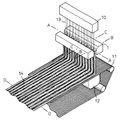
図1は、冷却延伸装置1の斜視図を含む繊維ウェブ14を製造する工程斜視図であり、繊維ウェブ14とコンベア11との一部を省略して示す。製造工程は、多数の連続フィラメント13を供給する紡糸ノズル10と、溶融紡糸されたフィラメント13を冷却、延伸する冷却延伸装置1と、冷却延伸されたフィラメント13を捕集するネット状の捕集コンベア11と、コンベア11の下方に位置して空気をコンベア11の上面から下面へ吸引するサクション装置12とで構成されている。ノズル10と装置1とコンベア11とは、所要の距離離間して配置されている。ノズル10からは、略一定の速度と略一定の坪量でフィラメント13が供給されている。
【0015】
ノズル10から放出されたフィラメント13は、装置1に入り、装置1内で冷却されつつ延伸されて装置1から出る。装置1から出たフィラメント13はコンベア11上に捕集され、コンベア11上に繊維ウェブ14が形成される。図示はしていないが、コンベア11上の繊維ウェブ14は、高圧水流を繊維ウェブ14に噴射してフィラメント13どうしを交絡させる処理、バーブのついた針で繊維ウェブ14をパンチしてフィラメント13どうしを交絡させる処理、または、熱風を繊維ウェブ14に噴射してフィラメント13どうしを熱融着する処理、接着剤を用いてフィラメント13どうしを接着する処理等が行われて不織布となる。
【0016】
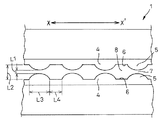
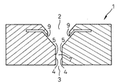
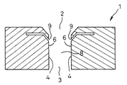
図2は、一部を省略して示す図1における装置1のA−A線断面図であり、図3,4は、図1における装置1のB−B線断面図と、図1における装置1のC−C線断面図とである。それら図では、フィラメント13を省略して示す。装置1は、フィラメント13の流入口2と、フィラメント13の流出口3と、流出入口2,3の間でフィラメント13の供給方向と交差する幅方向へ互いに対向離間して延びる両側面4と、流入口2の近傍に位置して流出口3の方向へ加圧空気を供給するエアー供給口9とを有する。
【0017】
装置1の両側面4の間には、フィラメント13が通過することができる間隙7,8が形成されている。装置1は、フィラメント13が間隙7,8を通過するときに、供給口9から間隙7,8内に供給される空気でフィラメント13を冷却しつつ延伸する。
【0018】
装置1の両側面4には、フィラメント13の供給方向と交差する幅方向へ互いに等しい間隔で離間する多数の山部5と、山部5の間に位置して幅方向へ互いに等しい間隔で離間する多数の谷部6とが形成されている。両側面4では、山部5と谷部6とが互いに向かい合うように対向配置されている。山部5は、断面が両側面4から間隙7の内方へ向かって弧を画く半球状を呈し、谷部6は、山部5の間で扁形状に延びている。山部5には角がないので、間隙7を通る空気に乱流が発生することを防止することができ、フィラメント13の流れに乱れが生ずることを防ぐことができる。
【0019】
山部5の間に形成された間隙7の最小寸法L1は、谷部6の間に形成された間隙8の最小寸法L2よりも小さい。供給口9から供給された空気は、山部5と谷部6との間の間隙7,8それぞれを通るが、そのときに空気圧に高低が生じる。山部5の間の間隙7では、山部5の圧力抵抗により空気圧が高くなり、谷部6の間の間隙8では、山部5の間の間隙7よりも空気圧が低くなる。空気圧の高い山部5の間の間隙7では空気の流速が小さくなり、空気圧の低い谷部6の間の間隙8では空気の流速が大きくなる。
【0020】
山部5の間の空気の流速の小さい間隙7に比べ、谷部6の間の空気の流速の大きい間隙8に、ノズル10から放出されたフィラメント13の多くが流入する。さらに、空気の流速の小さい間隙7を通るフィラメント13の伸長される割合に比べ、空気の流速の大きい間隙8を通るフィラメント13の伸長される割合が大きくなるので、谷部6の間の間隙8を通るフィラメント13の繊度が小さくなる。フィラメント13がコンベア11に捕集されたときに、谷部6の間の間隙8を通ったフィラメント13の密度と嵩とが、山部5の間の間隙7を通ったフィラメント13のそれよりも増し、製造された繊維ウェブ14に繊維ウェブ14の長手方向へ延びる縞状の模様が形成される。
【0021】
装置1では、山部5の間の間隙7の最小寸法L1を、谷部6の間の間隙8の最小寸法L2で除したときの値が0.1〜0.7の範囲にあることが好ましい。0.1より小さいと、山部5の間の間隙7の寸法L1が谷部6の間の間隙8の寸法L2と比べて小さくなりすぎ、フィラメント13が谷部6の間の間隙8に集中して流入し、山部5の間の間隙7を通過するフィラメント13の坪量が少なくなるので、繊維ウェブ14に極端に密度の低い部分が生じてしまうことがある。0.7を超えると、山部5と谷部6との間の間隙7,8の寸法L1,L2差が小さくなるので、それら間隙7,8に所期する空気の流速の大小が起こらず、繊維ウェブ14全体の密度が略均一となって繊維ウェブ14に縞模様を形成することができない場合がある。
【0022】
装置1では、山部5の幅方向へ延びる寸法L3が10〜100mmの範囲、谷部6の幅方向へ延びる寸法L4が10〜100mmの範囲にあることが好ましい。山部5と谷部6とのそれら寸法L3,L4が10mmよりも小さいと、供給する空気の流量や流速にもよるが、多数の山部5と多数の谷部6とが互いに近接し、それらの間の間隙7,8を通る空気が互いに干渉して間隙7,8内で乱流が生じたり、流出口3近傍で伴流が生じ易くなるので、フィラメント13の流れが乱されて繊維ウェブ14に明確な縞模様を形成することができないことがある。山部5と谷部6とのそれら寸法L3,L4が100mmを超えると、山部5どうしと谷部6どうしとの間隔が大きくなりすぎて繊維ウェブ14に細かい縞模様を形成することができない。
【0023】
山部5の寸法L3が10mmよりも小さく、谷部6の寸法L4が100mmを超える場合は、フィラメント13が谷部6の間の間隙8に集中して流入し、山部5の間の間隙7を通過するフィラメント13の坪量が少なくなり、製造された繊維ウェブ14に極端に密度の低い部分が生じてしまうことがある。逆に、山部5の寸法L3が100mmを超え、谷部6の寸法L4が10mmよりも小さい場合は、ノズル10からのフィラメント13の供給量が一定ならば、山部5の間の間隙7を通過するフィラメント13の坪量も多くなるので、山部5と谷部6との間の間隙7,8を通過するフィラメント13の坪量にほとんど差がなくなり、繊維ウェブ14に縞模様が明確に表れない場合がある。
【0024】
装置1は、図2に矢印X−X′で示す幅方向へ振幅させることもできる。装置1を振幅させることで、製造された繊維ウェブ14に曲折して延びる縞模様を形成することができる。装置1を矢印X−X′のいずれか一方へ移動させることで、繊維ウェブ14の長手方向と交差する方向へ傾斜する縞模様を形成することができる。
【0025】
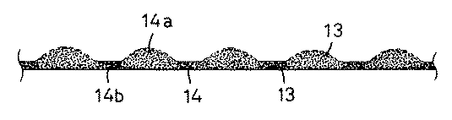
図5は、製造された繊維ウェブ14の図1におけるD−D線断面図である。繊維ウェブ14には、フィラメント13の密度と嵩とが大きい部分14aと、部分14aに比べてフィラメント13の密度と嵩とが小さい部分14bとが形成されている。部分14aは部分14bよりも上方へ隆起し、繊維ウェブ14の長手方向へ延びる部分14aと部分14bとが繊維ウェブ14に縞模様を形成する。
【0026】
冷却延伸装置1には、エアー供給口9を形成することなく、装置1の下方にサクション装置を設け、空気の流れを作ってもよい。供給される空気は、室温でも室温よりも低い温度でもよい。山部5は、断面が半球状の他に、断面が半楕円形や方せん体または三角形等であってもよい。
【0027】
フィラメント13としては、ポリオレフィン系、ポリエステル系、ポリアミド系等の各熱可塑性合成樹脂で形成されたものを使用することができる。また、熱可塑性合成樹脂で形成されたエラストマを使用することもできる。エラストマとしては、ポリオレフィン系、ポリエステル系、ポリアミド系、ポリウレタン系等のものを使用することができる。
【0028】
【発明の効果】
本発明に係る冷却延伸装置によれば、フィラメントに静電気を帯電させる静電開繊装置を設けることなく、安価に模様を付与した繊維ウェブを製造することができる。
【0029】
装置の側面に形成された山部と谷部との間の間隙の寸法や、山部と谷部との幅方向の寸法を変更することで、フィラメントの密度と嵩とを適宜変更して繊維ウェブを形成することができ、繊維ウェブに細かい縞模様や粗い縞模様のいずれをも形成することができる。
【図面の簡単な説明】
【図1】装置の斜視図を含む繊維ウェブを製造する工程斜視図。
【図2】一部を省略して示す図1における装置のA−A線断面図。
【図3】図1における装置のB−B線断面図。
【図4】図1における装置のC−C線断面図。
【図5】製造された繊維ウェブの図1におけるD−D線断面図。
【符号の説明】
1 冷却延伸装置
2 流入口
3 流出口
4 両側面
5 山部
6 谷部
7 間隙
8 間隙
9 エアー供給口
10 紡糸ノズル
11 捕集コンベア
12 サクション装置
13 フィラメント
14 繊維ウェブ
L1 最小寸法
L2 最小寸法
L3 寸法
L4 寸法[0001]
BACKGROUND OF THE INVENTION
The present invention relates to a cooling and drawing apparatus for cooling and drawing a large number of melt-spun filaments in a fiber web manufacturing process.
[0002]
[Prior art]
Japanese Patent Laid-Open No. 7-109658 discloses electrostatic opening in a spinning process in which a large number of continuous filaments are discharged from a spinning nozzle extending in the width direction of an apparatus toward a collecting conveyor that travels to form a fiber web on the conveyor. Disclosed is a method for producing a patterned fiber web with an intervening device.
[0003]
The electrostatic opening device charges the filament with static electricity and opens it with the repulsive force of each charged filament. The electrostatic opening device is charged with an arbitrary width, time, and voltage according to a preset program. It is given to the web.
[0004]
[Problems to be solved by the invention]
The method disclosed in Japanese Patent Laid-Open No. 7-109658 requires an electrostatic opening device that applies a voltage to a filament in response to a command from a computer programmed in advance in order to impart a pattern to a fiber web. The production of the fiber web is costly.
[0005]
An object of the present invention is to provide a cooling and stretching apparatus capable of manufacturing a fiber web having a pattern at a low cost without requiring an electrostatic opening device for charging a filament with static electricity in the manufacturing process of the fiber web. It is in.
[0006]
[Means for Solving the Problems]
In order to solve the above-described problems, the present invention presupposes that a plurality of continuous filament inlets that are melt-spun and that are interposed in the fiber web manufacturing process, the filament outlets, and the outlets A cooling and stretching apparatus that has both side surfaces that extend opposite to each other in the width direction intersecting with the filament supply direction, and that stretches while cooling the filament that passes through the gap between the both side surfaces.
[0007]
Under such a premise, as a feature of the present invention, the both side surfaces are formed with a number of ridges arranged at a predetermined interval in the width direction and a number of valleys extending between the ridges, The section is disposed opposite to the both side surfaces at equal intervals in the width direction and has a hemispherical shape in which a cross section forms an arc from the both side surfaces toward the inside of the gap. Are spaced apart from each other at equal intervals in the width direction and extending in a flat shape so as to be opposed to the both side surfaces, and the cooling and stretching device can swing in the width direction .
[0008]
[0009]
[0010]
As an example of an embodiment of the present invention, the dimension of the peak portion extending in the width direction is in the range of 10 to 100 mm, and the dimension of the valley portion extending in the width direction is in the range of 10 to 100 mm. .
[0011]
[0012]
[0013]
DETAILED DESCRIPTION OF THE INVENTION
The details of the cooling and stretching apparatus according to the present invention will be described with reference to the accompanying drawings.
[0014]
FIG. 1 is a process perspective view for manufacturing a
[0015]
The
[0016]
2 is a cross-sectional view taken along line AA of the
[0017]
Between both
[0018]
On both
[0019]
The minimum dimension L1 of the gap 7 formed between the
[0020]
Most of the
[0021]
In the
[0022]
In the
[0023]
When the dimension L3 of the
[0024]
The
[0025]
FIG. 5 is a cross-sectional view of the manufactured
[0026]
The cooling and stretching
[0027]
As the
[0028]
【The invention's effect】
According to the cooling and stretching apparatus according to the present invention, a fiber web having a pattern can be produced at low cost without providing an electrostatic fiber opening apparatus that charges the filament with static electricity.
[0029]
By changing the size of the gap between the crests and troughs formed on the side of the device and the widthwise dimension between the crests and troughs, the density and bulk of the filament can be appropriately changed to change the fiber A web can be formed, and both a fine stripe pattern and a rough stripe pattern can be formed on a fiber web.
[Brief description of the drawings]
FIG. 1 is a perspective view of a process for producing a fibrous web including a perspective view of an apparatus.
FIG. 2 is a cross-sectional view of the apparatus in FIG.
3 is a cross-sectional view of the device in FIG. 1 along the line BB.
4 is a cross-sectional view of the device in FIG.
5 is a sectional view of the manufactured fiber web taken along the line DD in FIG. 1. FIG.
[Explanation of symbols]
DESCRIPTION OF
Claims (2)
前記両側面には、前記幅方向へ所要の間隔で並ぶ多数の山部と前記山部の間に延びる多数の谷部とが形成され、前記山部は、前記幅方向へ互いに等しい間隔で離間して前記両側面に対向配置されていると共に、断面が前記両側面から前記間隙の内方へ向かって弧を描く半球状を呈し、前記谷部は、前記幅方向へ互いに等しい間隔で離間して扁形状に延びていて前記両側面に対向配置され、
前記冷却延伸装置が、前記幅方向へ振幅可能であることを特徴とする前記冷却延伸装置。A large number of continuous filament inlets that are melt-spun in the fiber web manufacturing process, the outlets of the filaments, and the outlets are spaced apart from each other in the width direction that intersects the filament supply direction. A cooling and stretching device that extends while cooling the filament that passes through the gap between the two side surfaces.
On both side surfaces, a large number of ridges arranged at a predetermined interval in the width direction and a large number of valleys extending between the ridge portions are formed, and the ridge portions are at equal intervals in the width direction. The cross section is arranged opposite to both side surfaces, and the cross section has a hemispherical shape that draws an arc from the both side surfaces toward the inside of the gap, and the valley portions are spaced apart from each other at equal intervals in the width direction. Extending in a flat shape and opposingly arranged on both side surfaces,
It said cooling stretching apparatus wherein the cooling stretching device, characterized in that it is a possible amplitude to the width direction.
Priority Applications (12)
| Application Number | Priority Date | Filing Date | Title |
|---|---|---|---|
| JP20150199A JP3623402B2 (en) | 1999-07-15 | 1999-07-15 | Cooling and stretching equipment |
| CA002313864A CA2313864C (en) | 1999-07-15 | 2000-07-13 | Cold drawing apparatus |
| BR0007327-0A BR0007327A (en) | 1999-07-15 | 2000-07-14 | Cold drawing device |
| MYPI20003230A MY122569A (en) | 1999-07-15 | 2000-07-14 | Cold drawing apparatus. |
| SG200003948A SG87134A1 (en) | 1999-07-15 | 2000-07-14 | Cold drawing apparatus |
| IDP20000593D ID26542A (en) | 1999-07-15 | 2000-07-14 | COLD ATTRACTION APARATUS |
| CNB001268147A CN1203222C (en) | 1999-07-15 | 2000-07-14 | Cooling stretching device |
| AU48624/00A AU767529B2 (en) | 1999-07-15 | 2000-07-14 | Cold drawing apparatus |
| US09/617,091 US6468063B1 (en) | 1999-07-15 | 2000-07-14 | Cold drawing apparatus |
| KR1020000040534A KR100638683B1 (en) | 1999-07-15 | 2000-07-14 | Cold stretching machine |
| EP00306058A EP1069215B1 (en) | 1999-07-15 | 2000-07-17 | Cold drawing apparatus |
| DE60017508T DE60017508T2 (en) | 1999-07-15 | 2000-07-17 | Apparatus for cold drawing |
Applications Claiming Priority (1)
| Application Number | Priority Date | Filing Date | Title |
|---|---|---|---|
| JP20150199A JP3623402B2 (en) | 1999-07-15 | 1999-07-15 | Cooling and stretching equipment |
Publications (2)
| Publication Number | Publication Date |
|---|---|
| JP2001032161A JP2001032161A (en) | 2001-02-06 |
| JP3623402B2 true JP3623402B2 (en) | 2005-02-23 |
Family
ID=16442110
Family Applications (1)
| Application Number | Title | Priority Date | Filing Date |
|---|---|---|---|
| JP20150199A Expired - Fee Related JP3623402B2 (en) | 1999-07-15 | 1999-07-15 | Cooling and stretching equipment |
Country Status (12)
| Country | Link |
|---|---|
| US (1) | US6468063B1 (en) |
| EP (1) | EP1069215B1 (en) |
| JP (1) | JP3623402B2 (en) |
| KR (1) | KR100638683B1 (en) |
| CN (1) | CN1203222C (en) |
| AU (1) | AU767529B2 (en) |
| BR (1) | BR0007327A (en) |
| CA (1) | CA2313864C (en) |
| DE (1) | DE60017508T2 (en) |
| ID (1) | ID26542A (en) |
| MY (1) | MY122569A (en) |
| SG (1) | SG87134A1 (en) |
Families Citing this family (7)
| Publication number | Priority date | Publication date | Assignee | Title |
|---|---|---|---|---|
| JP3658284B2 (en) * | 2000-07-05 | 2005-06-08 | ユニ・チャーム株式会社 | Nonwoven fabric manufacturing equipment |
| JP4889439B2 (en) * | 2006-10-23 | 2012-03-07 | 花王株式会社 | Elastic nonwoven fabric |
| US8246898B2 (en) * | 2007-03-19 | 2012-08-21 | Conrad John H | Method and apparatus for enhanced fiber bundle dispersion with a divergent fiber draw unit |
| CN101531455B (en) * | 2009-04-27 | 2011-06-08 | 中天科技光纤有限公司 | Optical fiber drawing cooling system |
| CN101831763B (en) * | 2010-05-27 | 2012-02-29 | 东莞市威骏不织布有限公司 | A kind of non-woven fabric forming equipment |
| DE112016002637B4 (en) * | 2015-06-12 | 2022-03-24 | Reliance Industries Limited | ELECTROSTATIC MIXING DEVICE AND METHOD FOR MIXING FILAMENTS |
| KR102391138B1 (en) * | 2018-03-29 | 2022-04-28 | 도레이 카부시키가이샤 | Drawing apparatus, and apparatus and method for manufacturing fibers and fibrous webs |
Family Cites Families (11)
| Publication number | Priority date | Publication date | Assignee | Title |
|---|---|---|---|---|
| US3554854A (en) | 1962-02-03 | 1971-01-12 | Freudenberg Carl Kg | Non-woven fabric |
| NL296015A (en) | 1962-05-16 | |||
| US4064605A (en) * | 1975-08-28 | 1977-12-27 | Toyobo Co., Ltd. | Method for producing non-woven webs |
| GB2105641B (en) * | 1981-08-08 | 1985-06-26 | Bridon Int Finance | Manufacture of filamentary polymer tow |
| DE3503818C1 (en) * | 1985-02-05 | 1986-04-30 | Reifenhäuser GmbH & Co Maschinenfabrik, 5210 Troisdorf | Device for stretching monofilament bundles |
| KR930011946B1 (en) * | 1991-12-27 | 1993-12-22 | 주식회사 코오롱 | Method for preparation of the latent characteristic polyester fiber |
| DE4312419C2 (en) * | 1993-04-16 | 1996-02-22 | Reifenhaeuser Masch | Plant for the production of a spunbonded nonwoven web from aerodynamically stretched plastic filaments |
| JPH07109658A (en) | 1993-10-08 | 1995-04-25 | Toyobo Co Ltd | Nonwoven filament cloth having pattern and its production |
| DE4409940A1 (en) * | 1994-03-23 | 1995-10-12 | Hoechst Ag | Process for stretching filament bundles in the form of a thread curtain, device suitable therefor and its use for producing spunbonded nonwovens |
| US5853628A (en) | 1996-09-12 | 1998-12-29 | Kimberly-Clark Worldwide, Inc. | Method of forming nonwoven fabric having a pore size gradient |
| GB2319745B (en) * | 1996-11-27 | 2001-01-10 | Du Pont | Spinning machine and conversion process |
-
1999
- 1999-07-15 JP JP20150199A patent/JP3623402B2/en not_active Expired - Fee Related
-
2000
- 2000-07-13 CA CA002313864A patent/CA2313864C/en not_active Expired - Fee Related
- 2000-07-14 SG SG200003948A patent/SG87134A1/en unknown
- 2000-07-14 US US09/617,091 patent/US6468063B1/en not_active Expired - Fee Related
- 2000-07-14 AU AU48624/00A patent/AU767529B2/en not_active Ceased
- 2000-07-14 BR BR0007327-0A patent/BR0007327A/en active Search and Examination
- 2000-07-14 ID IDP20000593D patent/ID26542A/en unknown
- 2000-07-14 CN CNB001268147A patent/CN1203222C/en not_active Expired - Fee Related
- 2000-07-14 MY MYPI20003230A patent/MY122569A/en unknown
- 2000-07-14 KR KR1020000040534A patent/KR100638683B1/en not_active Expired - Fee Related
- 2000-07-17 DE DE60017508T patent/DE60017508T2/en not_active Expired - Lifetime
- 2000-07-17 EP EP00306058A patent/EP1069215B1/en not_active Expired - Lifetime
Also Published As
| Publication number | Publication date |
|---|---|
| JP2001032161A (en) | 2001-02-06 |
| CN1203222C (en) | 2005-05-25 |
| EP1069215B1 (en) | 2005-01-19 |
| SG87134A1 (en) | 2002-03-19 |
| EP1069215A3 (en) | 2001-06-27 |
| KR100638683B1 (en) | 2006-10-27 |
| CN1282810A (en) | 2001-02-07 |
| BR0007327A (en) | 2001-12-04 |
| KR20010049790A (en) | 2001-06-15 |
| DE60017508D1 (en) | 2005-02-24 |
| CA2313864C (en) | 2003-11-25 |
| MY122569A (en) | 2006-04-29 |
| AU4862400A (en) | 2001-01-18 |
| CA2313864A1 (en) | 2001-01-15 |
| ID26542A (en) | 2001-01-18 |
| US6468063B1 (en) | 2002-10-22 |
| EP1069215A2 (en) | 2001-01-17 |
| DE60017508T2 (en) | 2006-03-23 |
| AU767529B2 (en) | 2003-11-13 |
Similar Documents
| Publication | Publication Date | Title |
|---|---|---|
| JP7176076B2 (en) | Apparatus and method for producing nonwoven fabrics composed of endless filaments | |
| US3802817A (en) | Apparatus for producing non-woven fleeces | |
| EP0343978B1 (en) | Stabilized continuous filament web | |
| US3692618A (en) | Continuous filament nonwoven web | |
| US3969561A (en) | Biaxially oriented nonwoven fabrics and method of making same | |
| EP2126178B1 (en) | Method and apparatus for enhanced fiber bundle dispersion with a divergent fiber draw unit | |
| JP4549541B2 (en) | Equipment for opening and distributing fiber bundles during the production of nonwoven webs | |
| US3630816A (en) | Nonwoven sheets made from rectangular cross section monofilaments | |
| JP3623402B2 (en) | Cooling and stretching equipment | |
| CN1319692A (en) | Method and apparatus for making no-woven fabric | |
| CN117597480A (en) | Open-celled hydraulically patterned nonwovens and methods of making the same | |
| US4186463A (en) | Apparatus for making biaxially oriented nonwoven fabrics and method of making same | |
| US4054628A (en) | Method of making biaxially oriented nonwoven fabrics | |
| JP2586126B2 (en) | Long-fiber nonwoven fabric and method for producing the same | |
| JP2001207368A (en) | Apparatus and method for producing nonwoven fabric of filament | |
| JPH06306755A (en) | Production of melt-blow nonwoven fabric | |
| US4276106A (en) | Laying oriented fibrous webs | |
| JPS5988961A (en) | Production of nonwoven fabric | |
| CA1042172A (en) | Apparatus for making a biaxially oriented nonwoven fabric | |
| JPH07268753A (en) | Method for manufacturing a wide nonwoven web | |
| JPS589185B2 (en) | Japanese sagebrush | |
| JPS63282350A (en) | Production of bulky long fiber nonwoven fabric | |
| CN118531561A (en) | Ultrafine fiber material with folded three-dimensional structure and preparation method thereof | |
| JP2004339638A (en) | Air sucker | |
| JP2005238098A (en) | Filter medium for air filter and manufacturing method thereof |
Legal Events
| Date | Code | Title | Description |
|---|---|---|---|
| A131 | Notification of reasons for refusal |
Free format text: JAPANESE INTERMEDIATE CODE: A131 Effective date: 20040907 |
|
| A521 | Written amendment |
Free format text: JAPANESE INTERMEDIATE CODE: A523 Effective date: 20041018 |
|
| TRDD | Decision of grant or rejection written | ||
| A01 | Written decision to grant a patent or to grant a registration (utility model) |
Free format text: JAPANESE INTERMEDIATE CODE: A01 Effective date: 20041116 |
|
| A61 | First payment of annual fees (during grant procedure) |
Free format text: JAPANESE INTERMEDIATE CODE: A61 Effective date: 20041124 |
|
| R150 | Certificate of patent or registration of utility model |
Free format text: JAPANESE INTERMEDIATE CODE: R150 |
|
| FPAY | Renewal fee payment (event date is renewal date of database) |
Free format text: PAYMENT UNTIL: 20071203 Year of fee payment: 3 |
|
| FPAY | Renewal fee payment (event date is renewal date of database) |
Free format text: PAYMENT UNTIL: 20081203 Year of fee payment: 4 |
|
| FPAY | Renewal fee payment (event date is renewal date of database) |
Free format text: PAYMENT UNTIL: 20091203 Year of fee payment: 5 |
|
| FPAY | Renewal fee payment (event date is renewal date of database) |
Free format text: PAYMENT UNTIL: 20101203 Year of fee payment: 6 |
|
| FPAY | Renewal fee payment (event date is renewal date of database) |
Free format text: PAYMENT UNTIL: 20101203 Year of fee payment: 6 |
|
| FPAY | Renewal fee payment (event date is renewal date of database) |
Free format text: PAYMENT UNTIL: 20111203 Year of fee payment: 7 |
|
| FPAY | Renewal fee payment (event date is renewal date of database) |
Free format text: PAYMENT UNTIL: 20111203 Year of fee payment: 7 |
|
| FPAY | Renewal fee payment (event date is renewal date of database) |
Free format text: PAYMENT UNTIL: 20121203 Year of fee payment: 8 |
|
| FPAY | Renewal fee payment (event date is renewal date of database) |
Free format text: PAYMENT UNTIL: 20121203 Year of fee payment: 8 |
|
| FPAY | Renewal fee payment (event date is renewal date of database) |
Free format text: PAYMENT UNTIL: 20131203 Year of fee payment: 9 |
|
| R250 | Receipt of annual fees |
Free format text: JAPANESE INTERMEDIATE CODE: R250 |
|
| R250 | Receipt of annual fees |
Free format text: JAPANESE INTERMEDIATE CODE: R250 |
|
| R250 | Receipt of annual fees |
Free format text: JAPANESE INTERMEDIATE CODE: R250 |
|
| LAPS | Cancellation because of no payment of annual fees |