JP3620214B2 - Paper sheet separator - Google Patents
Paper sheet separator Download PDFInfo
- Publication number
- JP3620214B2 JP3620214B2 JP10293197A JP10293197A JP3620214B2 JP 3620214 B2 JP3620214 B2 JP 3620214B2 JP 10293197 A JP10293197 A JP 10293197A JP 10293197 A JP10293197 A JP 10293197A JP 3620214 B2 JP3620214 B2 JP 3620214B2
- Authority
- JP
- Japan
- Prior art keywords
- feeding
- paper sheet
- letter
- paper
- paper sheets
- Prior art date
- Legal status (The legal status is an assumption and is not a legal conclusion. Google has not performed a legal analysis and makes no representation as to the accuracy of the status listed.)
- Expired - Fee Related
Links
Images


Description
【0001】
【発明の属する技術分野】
本発明は、束状の紙葉類を一枚づつに分離して繰り出す装置に係り、特に、紙葉類のサイズ、厚さ、材質の異なる書状を一枚づつに分離して繰り出す書状の分離装置に関する。
【0002】
【従来の技術】
紙葉類を一枚づつに分離して繰り出す装置の例として、例えば特開平7‐97092号公報に示されるシート給送装置がある。この装置では、下向きに凸となる点を境に第一と第二のシート吸着部を設けるとともに、第二のシート吸着部の吸着面からシート側に突出した突起ローラを退避可能に設けている。そして、第一と第二のシート吸着部に吸着されたシートを突起ローラにより変形させ、シートが二枚重なっていた場合にはこれらのシートの間に隙間を設けて空気を吹き込むようにしたものである。
【0003】
また、束状の紙葉類を一枚づつに分離して繰り出す装置の他の例として、例えば特開平6‐321372号公報に示される発送物を個々に取り出す装置がある。この装置では、紙葉類(発送物)が重ねて引き出されるいわゆる重送を防ぐため、紙葉類が積載される支え面内、及び紙葉類を案内する案内壁の範囲に紙葉類間に圧力空気を吹き付けるためのノズルを配置し、また別のノズルを案内壁と通過ギャップの間に配置している。そして、これらのノズルから紙葉類の搬送方向とは逆方向で所定の傾きで圧力空気を吹き出すことで紙葉類を離解させ重送の低減を図っている。それでもなお連行される紙葉類はストリッパーによって搬送が抑制され重送が低減される。
【0004】
【発明が解決しようとする課題】
上記第一の従来例は、シートトレイ上に積載された紙葉類を上方へエアによって吸着して水平方向へ一枚づつに分離して送り出すものである。従って、繰り出される紙葉類に対して搬送方向へ重力成分が作用するような紙葉類の分離装置の重送は、単に突起を設けるだけでは低減できない問題がある。またこの方式では、重量が重い紙葉類を持ち上げることはできず、さらに封筒書状のような曲げ剛性が高い紙葉類では同一平面上にない吸着面に紙葉類を吸着させることは困難である。
【0005】
上記第二の従来例も、紙葉類を一枚づつに分離して繰り出す際の重送を低減するために、圧力空気を用いて束状の紙葉類の間に空間を生じさせようとするものである。しかし、この従来例においても、積載手段上の紙葉類が送り手段の方向へ送られる際に束状の紙葉類には重力の成分が作用するため紙葉類の束の先端部がくさび状となって繰り出されようとするため紙葉類の間には十分に空間を形成することができず重送を低減することができない問題があった。
【0006】
本発明の目的は、繰り出される紙葉類に対して搬送方向へ重力成分が作用するような紙葉類の分離装置において、繰り出しの際に生じる重送を低減させようとするものである。
【0007】
【課題を解決するための手段】
上記目的は、束状の紙葉類を積載するための積載手段と、前記積載手段上の紙葉類を順に繰り出すための繰り出し手段と、前記積載手段上の束状の紙葉類を前記繰り出し手段の方向へ送るための送り手段と、前記積載手段上の紙葉類を前記繰り出し手段の方向へ吸引し、かつ繰り出し手段に紙葉類が吸着して繰り出されるように、その内部が負圧となるチャンバと、紙葉類が前記繰り出し手段に吸着されて繰り出される際に、繰り出される紙葉類に隣り合った紙葉類が同時に繰り出されることを防ぐ抵抗手段と、前記積載手段上の紙葉類が前記繰り出し手段に吸着したことを検知する検知手段と、前記積載手段上の紙葉類の最前部付近に圧力空気を吹き付ける吹き出し手段とを有し、前記繰り出し手段と繰り出される紙葉類が接触する接触面の位置より積載手段側に突出させて繰り出し手段近傍に送られてきた紙葉類を変形させる突起手段を、紙葉類の繰り出し方向と反対側である後端側角部の両方に対応させて設けると共に、左右の突起手段の突出量は異なるにより達成することができる。
【0008】
また、上記目的は、繰り出される紙葉類に対して搬送方向へ重力成分が作用するような紙葉類の分離装置において、束状の紙葉類を積載するための積載手段、前記積載手段上の紙葉類を順に繰り出すための繰り出し手段、前記積載手段上の束状の紙葉類を前記繰り出し手段の方向へ送るための送り手段、前記積載手段上の紙葉類を前記繰り出し手段の方向へ吸引し、かつ繰り出し手段に紙葉類が吸着して繰り出されるように、その内部が負圧となるチャンバ、紙葉類が前記繰り出し手段に吸着されて繰り出される際に、繰り出される紙葉類に隣り合った紙葉類が同時に繰り出されることを防ぐ抵抗手段、前記積載手段上の紙葉類が前記繰り出し手段に吸着したことを検知する検知手段、前記積載手段上の紙葉類の最前部付近に圧力空気を吹き付ける吹き出し手段を有し、前記繰り出し手段と繰り出される紙葉類が接触する接触面より積載手段側に突出させて取り付けられ、繰り出し手段に吸着された紙葉類を変形させる第1の突起手段を、吸着された紙葉類の先端側角部に対応させて少なくとも一つ設け、前記繰り出し手段と繰り出される紙葉類が接触する接触面の位置より積載手段側に突出させて取り付けられ、繰り出し手段近傍に送られてきた紙葉類を変形させる第2の突起手段を、送られてきた紙葉類の後端側角部に対応させて少なくとも一つ設けたことにより達成される。
【0010】
【発明の実施の形態】
以下、本発明の一実施例として、はがき、封書等の郵便書状を分離して繰り出す書状分離装置の例を図1〜図5を用いて説明する。
【0011】
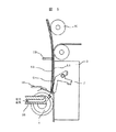
図1は、本発明の紙葉類の分離装置の一実施例である書状分離装置の概略図である。
【0012】
図1の分離装置は、重力方向に近い方向へ書状を繰り出す構成ものである。
【0013】
分離すべき束状の書状を積載するための積載台1と、積載台1上の束状の書状の最前の書状を繰り出すための繰り出し手段である複数本の繰り出しベルト2と、積載台1上の束状の書状の最前部を、繰り出しベルト2の方向へ吸引し、さらに繰り出しベルト2に書状が吸着して繰り出されるように、その内部が負圧となるチャンバ3が設けられている。
【0014】
さらに、束状の書状の最前の書状が繰り出しベルト2に吸着されて繰り出される際に、繰り出される書状に隣り合った書状が連行して同時に繰り出されることを防ぐための抵抗手段である分離ローラ4と、積載台1上の書状の最前部付近の書状に圧力空気を吹き付ける吹き出しノズル5A、5Bと、最前の書状が繰り出しベルトに吸着したことを検知するための検知レバー6A、6Bとが設けられている。
【0015】
また、繰り出し手段に吸着された書状を変形させる第1の突起手段として、繰り出しベルト2の吸着面より積載台1側に突出し、かつ繰り出される書状の先端側角部に対応して突起レバー7が設けられている。この第1の突起手段はローラで構成することも可能である。
【0016】
また、積載台1上の束状の書状を繰り出しベルト2の方向へ送るため積載台1側には送りベルト8が設けられ、フレーム14側にはフレーム14に設けられた長孔部28から突き出したフォーク9が繰り出しベルト2の吸着面より積載台1側に突出して取り付けられている。
【0017】
また、繰り出される書状の後端側角部に対応して第2の突起手段としてのローラ10,10Aが設けられている。なおこの第2の突起手段はレバーとしてもよい。
【0018】
さらに、書状後端側の前方への倒れを支える上部ガイド11と、検知レバー6A又は6Bの位置を検出する発光素子と受光素子からなる検知レバーセンサ12と、繰り出される書状や後続の書状の先端位置を検出する複数のセンサからなる書状位置検出センサ13等から構成されている。
【0019】
繰り出しベルト2は、書状を繰り出すために表面は摩擦係数の高い材料で被覆されている。また、繰り出しベルト2は、チャンバ3の負圧を書状へ作用させるための複数の穴15が設けられている。
【0020】
繰り出しベルト2は、図2に示すように、これを駆動するためのプーリ16、及び繰り出しベルトに従動して回転するローラ17に所定の張力でかけられている。駆動プーリ16は図示されないサーボモータにより駆動される。さらに、本実施例における繰り出しベルト2は、摩耗しにくいハードベルトが用いられている。
【0021】
チャンバ3の積載台側の面にも、繰り出しベルト2の穴15と同様に穴が設けられている。チャンバ3の内部は、図示されないブロアによって大気圧よりも低い負圧状態となっており、この負圧により積載台1上の書状は繰り出しベルト2の方向へ吸引されて引き寄せられ、繰り出しベルトに吸着する。繰り出される書状に作用する搬送力は、この吸着力と繰り出しベルト2の摩擦係数が高いほど大きくなる。
【0022】
分離ローラ4は、図3に示すように複数の繰り出しベルト2の間に来るように配置されている。また、分離ローラ4は、繰り出しベルト2の表面の位置よりチャンバ3側へ入り込んだ状態で配置されている。このように配置すると、1枚目の書状の先端部は分離ローラ4と繰り出しベルト2に沿って波形に変形するが、2枚目以降の書状は変形が生じにくいため、繰り出される書状以外の書状は、分離ローラ4と繰り出しベルト2の間に進入しにくくなり、書状の重送を防ぐことができる。
【0023】
本実施例の紙葉類に抵抗力を作用させる分離ローラ4は、その外周に高摩擦部材を有している。また、分離ローラ4の回転中心に位置する支持軸41と、分離ローラ4の回転中心と異なる位置に中心を持つ他の軸42と、軸42と支持軸41を連結する連結手段としてアーム43、分離ローラ4が所定の位置に戻るような回転ばね44が設けられている。そして紙葉類に抵抗力を作用させる効果を確実にするために、分離ローラ4を紙葉類の搬送方向に複数個設けた。
【0024】
分離ローラ4は、繰り出される書状の厚さに対応して動くことができるように、ばね手段によりチャンバ3に押し付けるように取り付けられている。分離ローラ4とチャンバ3は接触していても良いが他のストッパを用いて分離ローラ4の位置を決め、分離ローラ4とチャンバ3の間に隙間を設けても良い。
【0025】
束状の書状の最前部付近に設けた、圧力空気を吹き付ける吹き出しノズル5A、5Bは、フレーム14側と積載台1に隣接したガイド18の端部側の二カ所に設けられている。フレーム14の裏側やガイド18の下側には図示されないチャンバが設けられ、さらにこのチャンバには、やはり図示されないブロアから圧力空気が供給されノズルから吹き出される。
【0026】
ガイド18の端部に設けられたノズル5Aは積載台1上の書状の束の最前部付近を、フレーム14に設けられたノズル5Bは、積載台1上の書状の束と繰り出しベルト2に吸着された書状の近傍に圧力空気を吹き付ける。フレーム14に設けられた吹き出しノズル5Bの高さ位置は、チャンバ3の最上の孔とローラ10の最下部のものの間であり、ガイド18に設けられた吹き出しノズルの位置は奥側の突出ローラ10Aより手前側である。
【0027】
手前側の検知レバー6Aは、図2に示すようにくの字状の形状をしており、軸19に回転自在に運動するように取り付けられている。検知レバーの一部には、ばね20が取り付けられ、ばね20はばね取り付け軸21にかけられている。また、検知レバー6Aの書状接触部と反対側の端部近傍にはストッパ22が設けられており、ばね力による検知レバーの回転を阻止している。
【0028】
書状が書状吸着面A上にない場合には、検知レバー6Aの書状接触部は書状吸着面Aより積載台1側に突出した位置にあるようにストッパ22の位置が調整されている。そして、書状が書状吸着面A上にある場合には、書状接触部が吸着された書状に押されて書状吸着面より引っ込む様に構成されている。
【0029】
奥側の検知レバー6Bも軸19に回転自在に運動するように取り付けられている。また、奥側検知レバー6Bの一部にもばね23が取り付けられ、ばね23はばね取り付け軸21にかけられている。さらに、奥側検知レバー6Bの書状接触部と反対側の端部近傍にもストッパ22が設けられており、ばね力による奥側検知レバー6Bの回転を阻止している。
【0030】
本実施例では、書状が繰り出しベルト2に接触する接触面Aより積載台1側に突出させて取り付けられた突起レバー7は、吸着された書状の先端側角部の位置と、抵抗手段である分離ローラ4の直前で停止している書状のの先端側角部の位置の両方に対応できるようにチャンバ3の手前側の側面に取り付けられている。また、突起レバー7は、図4に示すように軸23に回転自在に運動するように取り付けられている。突起レバーの7一部には、ばね24が取り付けられ、ばね24はばね取り付け軸25にかけられている。また、突起レバー7の近傍にはストッパ26が設けられており、ばね力による突起レバー7の回転を阻止している。
【0031】
本実施例では、ストッパ26にはネジが用いられており、このネジによって突起レバー7の突出量が調整される。そして書状が書状吸着面A上にない場合には、突起レバー7の書状接触部が検知レバー6A、6Bの書状接触部より突出しないような位置に調整されている。
【0032】
積載台1上では、送りベルト8の書状搬送面8Aが積載台1の表面より幾分高くなるように設けられている。送りベルト8は、図2に示されるように、駆動プーリ27により駆動される。駆動プーリ27には図示されないサーボモータから駆動力が伝達されている。送りベルト8の書状搬送面は、書状が搬送できるように摩擦係数が高い材料で被覆されている。
【0033】
フォーク9はフレーム14に設けられた長孔部28から突き出されるようにして設けられている。フォーク9はフレーム14の裏側で図示されないチェインに取り付けられ、図示されないサーボモータで駆動される。
【0034】
送りベルト8とフォーク9は同期して駆動される。駆動のオン、オフは、検知レバー6A、6Bの動作で決定される。書状吸着面上に書状が無く、検知レバー6の書状接触部が書状吸着面Aより出ている場合には、検知レバー6A、6Bは検知レバーセンサ12の発光素子から出ている光を遮光しない。この時には送りベルト8とフォーク9は積載台1上の書状を繰り出しベルト2の方向へ送るように駆動される。書状が吸引され繰り出しベルト2に吸着された場合には吸着力により検知レバー6A、6Bが押し込まれる。この時検知レバー6A、6Bは検知レバーセンサ12を遮光し、この信号で送りベルト8とフォーク9の駆動は停止される。
【0035】
また本実施例では、書状が繰り出しベルト2に接触する接触面Aより積載台1側に突出させて取り付けられた突起手段としてのローラ10は、吸着された書状の後端側角部の位置に対応できるように取り付けられている。ローラ10は、図2に示すように軸29に回転自在に運動するように取り付けられている。ローラ10を保持するレバー30一部には、ばね31が取り付けられ、ばね31はばね取り付け軸32にかけられている。レバー30の近傍にはストッパ33が設けられており、ばね力によるレバー30の回転を阻止している。
【0036】
積載台1のチャンバ3側にはガイド18が設けられており、さらにその先端部には分離ローラ4と繰り出しベルト2の間への書状の過度の落ち込みを防ぐための可撓性の弾性材からなる補助ガイド34が設けられている。積載台1の表面やガイド18、補助ガイド34の表面は書状の送りが円滑に行われるように摩擦係数の低い材料で被覆されている。
【0037】
繰り出しベルト2の近傍まで送られてきた書状のうち、薄手の書状はその重量も小さいためチャンバ3からの吸引力で容易に繰り出しベルト2に吸着される。この時、繰り出しベルト2に吸着された書状は検知レバー6A、6Bを押し込むため、送りベルト8やフォーク9の駆動が停止される。
【0038】
ところで前述したように、書状の後端側に設けられた突起手段としてのローラ10は、書状の吸着面Aより積載台1側に出た状態で取り付けられている。このため、書状の束が繰り出しベルト2の方へ送られた場合には、先に書状の後端側がローラ10に当接した後に書状先端側が吸着され、書状の束の密度は書状の後端側では高く先端側では低くなる。この状態で、先端側にはフレーム14とガイド25からの吹き出しノズル5A、5Bから圧力空気が吹き込まれるため、書状の先端側では書状間に隙間ができる。
【0039】
一方、書状の後端側では書状の密度が高いため、圧力空気によって隙間が生じにくい。このため後端側では書状は互いに接触し、ローラ10へ押しつけられた力によって摩擦力が働く。この摩擦力は、繰り出される書状に対しては搬送に対して抵抗力となるが、本発明では、この摩擦力が書状の重量より幾分大きくなるようにローラの位置やローラに連結されたばねの強さが設定されており、また繰り出される書状に作用する搬送力は、この抵抗力より大きくなるように設定されているため、書状の繰り出しに支障をきたさず、むしろ繰り出される書状の束の繰り出し側に近い部分が過度に積載台の高さ位置より落ち込むことを防ぐ。もし水平、あるいは水平に近い方向へ書状を繰り出す装置においては、重力が繰り出し方向に作用しないためこの効果はさらに大きい。
【0040】
本実施例では、奥側のローラの突出量が手前側のローラ10の突出量より大きいように設定されている。このように、積載台上の書状の束がフォーク9のような送り手段によって送られてくる場合、束の先頭の部分では突出量が大きいほど重送が生じにくい。しかし、突出量が大きいと束の途中の書状が繰り出される場合には隙間がないため書状後端側で後続の書状に搬送力が働き重送が生じることがわずかではあるが発生する。このため、本実施例では奥側と手前側のローラ10の突出量を異ならせることによって、書状の後端側の部分にも幾分隙間ができるようにした。これにより上述の問題は解決され、より重送を低減することができる。
【0041】
突出ローラ10の突出量は、繰り出しベルト2とガイド18の間の隙間寸法よりあまりに大きくなると、前述した押しつけ力が大きくなるため抵抗力も大きくなり、搬送できない場合も生じたり、書状が後ろ側へ倒れるため逆に書状の間に隙間が生じにくくなることがある。従ってローラ10の突出量は繰り出しベルト2とガイド18の隙間寸法程度より小さくすることが望ましい。
【0042】
突出ローラ10の突出量は、繰り出しベルト2とガイド18の間の隙間寸法よりあまりに大きくなると、前述した押しつけ力が大きくなるため抵抗力も大きくなり、搬送できない場合も生じたり、書状が後ろ側へ倒れるため逆に書状の間に隙間が生じにくくなることがある。従ってローラ10の突出量は繰り出しベルト2とガイド18の隙間寸法程度より小さくすることが望ましい。
【0043】
ところで、積載台上の書状の状態やフォークの送り量の関係で、繰り出しベルト2近傍の書状の束の先端部がくさび状になって分離ローラ直前の空間へ入り込むことがある。この時には大部分の書状には分離ローラ4からの抵抗力が働き、この抵抗力は繰り出される書状から作用する繰り出し力より大きいためこれらの書状が連行されて送られることはないが、書状の先端部の書状間に隙間がないため重送が発生することがある。
【0044】
そこで、この重送の発生を防止するために、突起レバー7を書状先端側角部に対応して設ける構成とした。すなわち、くさび状となって分離ローラ近傍まで落ち込んできた書状の先端側の角部は突起レバー7によって吸着面から離れており、また吸着面に対応した部分の書状は繰り出しベルトに吸着されるため、繰り出されようとする書状S1には、吸着面に対応した部分がくぼんだ三次元的な変形が生じる。本実施例では、書状後端側の角部に突出ローラ10が設けられているため、書状後端側も吸着面より離れるため、三次元的な変形がより生じやすくなっている。
【0045】
一方、繰り出しベルト2に吸着された書状S1に後続する書状S2には、チャンバ3からの吸引、吸着力は作用しない。従って、吸着面に対応した部分がくぼむような三次元的な変形は生じにくく単純曲げ変形に近い二次元的な変形状態となる。この時、繰り出しベルト2に吸着された薄い書状S1と後続の書状S2の間には上述の変形状態の違いから図5に示すようにくぼんだ部分に隙間Gができる。この隙間に吹き出しノズル5Bから圧力空気が吹き出されるため、書状S1、S2の間には大きな剥離力が作用する。従って、繰り出しベルト2近傍の書状の束の部分は、書状間に隙間ができて捌かれた状態となり、書状が連行されて繰り出される重送を防ぐことが容易となる。
【0046】
このとき、書状の隙間Gに搬送方向から圧力空気を吹き込むとより効果的である。従って、書状の搬送方向から圧力空気を吹き込むノズル35を設けても良い。なお、この効果はくさび状になった書状だけでなく、過度に落下していない書状に対しても効果があることはもちろんである。
【0047】
吹き出しノズルから吹き出される圧力空気の強さが過度に強いと、積載台1上の書状が吹き飛ばされたり分離時の姿勢が乱れる。従って、本実施例では吹き出しノズルからの圧力空気の強さは書状が吹き飛ばされず、また姿勢の乱れも少ない程度に調整されている。また、突起レバー7や検知レバー6に連結されたばね力が過度に大きいとレバーが完全に押し込まれず、特に厚い書状は繰り出しベルト2に吸着されず繰り出し不良となる。従って、本実施例では検知レバー6や突起レバー7のばねは、厚い書状を繰り出しベルト2に押しつけることが可能な程度のものが取り付けられているが、このような問題がない場合には、突起レバー7は固定されたものでもかまわないことはもちろんである。また、本実施例ではローラ10も退避可能なものとしたが、これが固定式のものであっても良いことはもちろんである。
【0048】
【発明の効果】
本発明により、繰り出される紙葉類の間に確実に隙間を生じさせることができ分離の際の重送を低減することができる。
【図面の簡単な説明】
【図1】紙葉類分離装置の一実施例としての書状分離装置の概略を示した図。
【図2】図1に示す装置の別なる説明図。
【図3】本実施例における繰り出しベルトと分離ローラの位置を示した図。
【図4】本実施例における突起レバーの取り付け状態を示した図。
【図5】分離の際の書状の変形状態を示した説明図。
【符号の説明】
1…積載台、2…繰り出しベルト、3…チャンバ、4…分離ローラ、5…吹き出しノズル、6…検知レバー、7…突起レバー、8…送りベルト、9…フォーク、10…突出ローラ、12…検知レバーセンサ、13…書状位置検出センサ、14…フレーム、18…ガイド、34…補助ガイド、35…吹き出しノズル。[0001]
BACKGROUND OF THE INVENTION
The present invention relates to an apparatus for separating and feeding out a bundle of paper sheets one by one, and in particular, separating a letter that separates and feeds out paper letters of different sizes, thicknesses, and materials one by one. Relates to the device.
[0002]
[Prior art]
As an example of an apparatus that separates and feeds paper sheets one by one, there is a sheet feeding apparatus disclosed in, for example, JP-A-7-97092. In this apparatus, the first and second sheet adsorbing portions are provided at a point that protrudes downward, and a protruding roller that protrudes from the adsorbing surface of the second sheet adsorbing portion to the sheet side is provided so as to be retractable. . Then, the sheets adsorbed on the first and second sheet adsorbing portions are deformed by the protruding rollers, and when two sheets overlap each other, a gap is provided between these sheets so as to blow air. It is.
[0003]
As another example of an apparatus for separating and feeding out bundled paper sheets one by one, for example, there is an apparatus for individually picking up shipments disclosed in Japanese Patent Laid-Open No. 6-321372. In this apparatus, in order to prevent so-called multi-feeding where paper sheets (shipments) are pulled out, paper sheets are placed within the support surface on which the paper sheets are stacked and within the guide wall that guides the paper sheets. A nozzle for blowing pressurized air is disposed on the other side, and another nozzle is disposed between the guide wall and the passage gap. Then, the compressed air is blown out from these nozzles at a predetermined inclination in the direction opposite to the direction in which the paper sheet is conveyed, whereby the paper sheet is disaggregated to reduce double feeding. Nevertheless, the paper sheets taken together are restrained from being transported by the stripper and the double feed is reduced.
[0004]
[Problems to be solved by the invention]
In the first conventional example, the paper sheets stacked on the sheet tray are attracted upward by air and separated and sent out one by one in the horizontal direction. Accordingly, there is a problem that the double feeding of the paper sheet separating apparatus in which the gravity component acts on the fed paper sheets in the transport direction cannot be reduced simply by providing the protrusions. Also, with this method, heavy paper sheets cannot be lifted, and it is difficult for paper sheets with high bending rigidity such as envelope letters to adsorb paper sheets to an adsorption surface that is not on the same plane. is there.
[0005]
The second conventional example also attempts to create a space between bundled paper sheets using compressed air in order to reduce double feeding when separating and feeding paper sheets one by one. To do. However, even in this conventional example, when the paper sheets on the stacking means are fed in the direction of the feeding means, a gravity component acts on the bundle of paper sheets, so that the leading end of the bundle of paper sheets is wedged. As a result, it is difficult to form a sufficient space between the paper sheets and to reduce the double feed.
[0006]
SUMMARY OF THE INVENTION An object of the present invention is to reduce double feeding that occurs during feeding in a paper sheet separating apparatus in which a gravity component acts in the transport direction on a fed paper sheet.
[0007]
[Means for Solving the Problems]
The object is to stack a stack of paper sheets, a feeding means for feeding out the paper sheets on the stacking means in order, and a bundle of paper sheets on the stacking means. The feeding means for feeding in the direction of the means, and the inside of the stacking means is negative pressure so that the paper sheets are sucked in the direction of the feeding means and the paper sheets are adsorbed and fed out by the feeding means. A chamber, a resistance means for preventing paper sheets adjacent to the paper sheet to be fed out simultaneously when the paper sheets are attracted and fed out by the feeding means, and the paper on the stacking means A paper sheet that has a detection means for detecting that the leaf has been adsorbed to the feeding means, and a blow-out means for blowing pressurized air to the vicinity of the frontmost part of the paper sheets on the stacking means; Contact surface Protruding means for deforming the paper sheet that is projected from the position to the stacking means side and sent to the vicinity of the feeding means is provided corresponding to both the rear end side corners opposite to the paper feeding direction. At the same time, the protrusion amounts of the left and right protrusion means can be achieved differently .
[0008]
Further, the object is to provide a stacking unit for stacking bundled sheets in the sheet separating apparatus in which a gravity component acts in the transport direction on the fed sheets, A feeding means for feeding out the paper sheets in order, a feeding means for feeding a bundle of paper sheets on the stacking means in the direction of the feeding means, and a direction of the paper sheets on the stacking means in the direction of the feeding means And a paper sheet that is fed out when the paper sheet is sucked and fed out by the feeding means so that the paper sheet is sucked and fed out by the feeding means. Resistance means for preventing paper sheets adjacent to each other from being simultaneously fed, detection means for detecting that the paper sheets on the stacking means are attracted to the feed means, and the foremost part of the paper sheets on the stacking means Blow pressure air near A first projecting means for projecting and attaching to the stacking means side from a contact surface where the feeding means and the paper sheet fed out contact, and deforming the paper sheets adsorbed by the feeding means. And at least one corresponding to the front end corner of the adsorbed paper sheet, and is attached to project from the position of the contact surface where the paper sheet to be fed and the paper sheet to be fed come into contact with the stacking means. This is achieved by providing at least one second projection means for deforming the paper sheet sent to the vicinity in correspondence with the rear end side corner of the sent paper sheet .
[0010]
DETAILED DESCRIPTION OF THE INVENTION
Hereinafter, as one embodiment of the present invention, an example of a letter separating apparatus for separating and feeding out post letters such as postcards and sealed letters will be described with reference to FIGS.
[0011]
FIG. 1 is a schematic view of a letter separating apparatus which is an embodiment of the paper sheet separating apparatus of the present invention.
[0012]
The separating device in FIG. 1 is configured to draw out a letter in a direction close to the direction of gravity.
[0013]
A stacking table 1 for stacking bundled letters to be separated, a plurality of
[0014]
Further, when the frontmost letter of the bundled letter is attracted to the
[0015]
Further, as a first projection means for deforming the letter adsorbed by the feeding means, the projection lever 7 protrudes from the suction surface of the
[0016]
Further, in order to send a bundled letter on the loading table 1 in the direction of the
[0017]
Further,
[0018]
Furthermore, the
[0019]
The feeding
[0020]
As shown in FIG. 2, the feeding
[0021]
Similarly to the
[0022]
As shown in FIG. 3, the
[0023]
The
[0024]
The
[0025]
Blowing
[0026]
The
[0027]
The detection lever 6 </ b> A on the near side has a dogleg shape as shown in FIG. 2, and is attached to the
[0028]
When the letter is not on the letter suction surface A, the position of the
[0029]
The
[0030]
In the present embodiment, the protruding lever 7 attached so that the letter protrudes from the contact surface A that contacts the feeding
[0031]
In this embodiment, a screw is used for the
[0032]
On the loading table 1, the letter conveying surface 8 </ b> A of the feed belt 8 is provided so as to be somewhat higher than the surface of the loading table 1. The feed belt 8 is driven by a
[0033]
The fork 9 is provided so as to protrude from a
[0034]
The feed belt 8 and the fork 9 are driven in synchronization. Driving on and off is determined by the operation of the detection levers 6A and 6B. When there is no letter on the letter suction surface and the letter contact portion of the detection lever 6 protrudes from the letter suction face A, the detection levers 6A and 6B do not block the light emitted from the light emitting element of the
[0035]
Further, in this embodiment, the
[0036]
A
[0037]
Of the letters sent to the vicinity of the feeding
[0038]
By the way, as described above, the
[0039]
On the other hand, since the density of the letter is high on the rear end side of the letter, a gap is hardly generated by the pressurized air. Therefore, the letters come into contact with each other on the rear end side, and a frictional force is exerted by the force pressed against the
[0040]
In the present embodiment, the protruding amount of the rear roller is set to be larger than the protruding amount of the
[0041]
If the protruding amount of the protruding
[0042]
If the protruding amount of the protruding
[0043]
By the way, depending on the state of the letter on the loading table and the feed amount of the fork, the leading end of the letter bundle near the feeding
[0044]
Therefore, in order to prevent the occurrence of this double feed, the projection lever 7 is provided corresponding to the corner portion on the leading end side of the letter. That is, the corner on the leading end side of the letter that has become wedge-shaped and has dropped to the vicinity of the separation roller is separated from the adsorption surface by the protruding lever 7, and the letter corresponding to the adsorption surface is adsorbed by the feeding belt. In the letter S1 to be fed out, a three-dimensional deformation occurs in which the portion corresponding to the suction surface is recessed. In the present embodiment, since the protruding
[0045]
On the other hand, the suction or suction force from the
[0046]
At this time, it is more effective to blow pressurized air into the letter gap G from the conveying direction. Therefore, you may provide the
[0047]
If the strength of the pressure air blown from the blowing nozzle is excessively strong, the letter on the loading table 1 is blown off or the posture during separation is disturbed. Therefore, in this embodiment, the strength of the pressure air from the blowing nozzle is adjusted so that the letter is not blown out and the posture is not disturbed. On the other hand, if the spring force connected to the protrusion lever 7 or the detection lever 6 is excessively large, the lever is not pushed in completely, and a particularly thick letter is not attracted to the feeding
[0048]
【The invention's effect】
According to the present invention, it is possible to reliably generate a gap between the fed paper sheets, and to reduce double feeding during separation.
[Brief description of the drawings]
FIG. 1 is a diagram showing an outline of a letter separating apparatus as an embodiment of a paper sheet separating apparatus.
FIG. 2 is another explanatory diagram of the apparatus shown in FIG. 1;
FIG. 3 is a diagram illustrating positions of a feeding belt and a separation roller in the present embodiment.
FIG. 4 is a diagram showing a mounting state of a protruding lever in the present embodiment.
FIG. 5 is an explanatory diagram showing a deformed state of a letter at the time of separation.
[Explanation of symbols]
DESCRIPTION OF
Claims (2)
Priority Applications (1)
| Application Number | Priority Date | Filing Date | Title |
|---|---|---|---|
| JP10293197A JP3620214B2 (en) | 1997-04-21 | 1997-04-21 | Paper sheet separator |
Applications Claiming Priority (1)
| Application Number | Priority Date | Filing Date | Title |
|---|---|---|---|
| JP10293197A JP3620214B2 (en) | 1997-04-21 | 1997-04-21 | Paper sheet separator |
Publications (2)
| Publication Number | Publication Date |
|---|---|
| JPH10291666A JPH10291666A (en) | 1998-11-04 |
| JP3620214B2 true JP3620214B2 (en) | 2005-02-16 |
Family
ID=14340595
Family Applications (1)
| Application Number | Title | Priority Date | Filing Date |
|---|---|---|---|
| JP10293197A Expired - Fee Related JP3620214B2 (en) | 1997-04-21 | 1997-04-21 | Paper sheet separator |
Country Status (1)
| Country | Link |
|---|---|
| JP (1) | JP3620214B2 (en) |
-
1997
- 1997-04-21 JP JP10293197A patent/JP3620214B2/en not_active Expired - Fee Related
Also Published As
| Publication number | Publication date |
|---|---|
| JPH10291666A (en) | 1998-11-04 |
Similar Documents
| Publication | Publication Date | Title |
|---|---|---|
| JP4866300B2 (en) | Paper feeding device and electrophotographic device | |
| JP2007331905A (en) | Paper feeder, its control method, and printer using this | |
| JP2788382B2 (en) | Paper feeder | |
| JP5203819B2 (en) | Paper sheet take-out device | |
| JPH057291B2 (en) | ||
| JPS61254438A (en) | Sheet feeder | |
| JP3525621B2 (en) | Paper sheet separation device | |
| JP3620214B2 (en) | Paper sheet separator | |
| JP3620198B2 (en) | Paper sheet separator | |
| JP3632405B2 (en) | Paper sheet separator | |
| JP2002128294A (en) | Sucking and carrying device for printing plate | |
| JP3220553B2 (en) | Paper feeder and image forming apparatus | |
| JP3817360B2 (en) | Paper sheet separator | |
| JP2954209B1 (en) | Paper sheet supply device and supply method | |
| JP2001039556A (en) | Paper feeding device | |
| JP3613048B2 (en) | Paper sheet separator | |
| JP2916874B2 (en) | Paper alignment device | |
| JP3531525B2 (en) | Paper sheet separation device | |
| JP3058237B2 (en) | Sheet feeding apparatus and image forming apparatus | |
| JP2001019187A (en) | Paper feeder | |
| JP3716103B2 (en) | Paper sheet separator | |
| JP6615261B2 (en) | Paper sheet processing equipment | |
| JPH10310272A (en) | Paper sheet separation device | |
| JPH1111722A (en) | Paper sheet separating device | |
| JP3464530B2 (en) | Origami printed matter supply device |
Legal Events
| Date | Code | Title | Description |
|---|---|---|---|
| A977 | Report on retrieval |
Free format text: JAPANESE INTERMEDIATE CODE: A971007 Effective date: 20040715 |
|
| A131 | Notification of reasons for refusal |
Free format text: JAPANESE INTERMEDIATE CODE: A131 Effective date: 20040727 |
|
| A521 | Written amendment |
Free format text: JAPANESE INTERMEDIATE CODE: A523 Effective date: 20040924 |
|
| TRDD | Decision of grant or rejection written | ||
| A01 | Written decision to grant a patent or to grant a registration (utility model) |
Free format text: JAPANESE INTERMEDIATE CODE: A01 Effective date: 20041026 |
|
| A61 | First payment of annual fees (during grant procedure) |
Free format text: JAPANESE INTERMEDIATE CODE: A61 Effective date: 20041108 |
|
| S111 | Request for change of ownership or part of ownership |
Free format text: JAPANESE INTERMEDIATE CODE: R313111 |
|
| R350 | Written notification of registration of transfer |
Free format text: JAPANESE INTERMEDIATE CODE: R350 |
|
| FPAY | Renewal fee payment (event date is renewal date of database) |
Free format text: PAYMENT UNTIL: 20071126 Year of fee payment: 3 |
|
| FPAY | Renewal fee payment (event date is renewal date of database) |
Free format text: PAYMENT UNTIL: 20081126 Year of fee payment: 4 |
|
| FPAY | Renewal fee payment (event date is renewal date of database) |
Free format text: PAYMENT UNTIL: 20091126 Year of fee payment: 5 |
|
| FPAY | Renewal fee payment (event date is renewal date of database) |
Free format text: PAYMENT UNTIL: 20101126 Year of fee payment: 6 |
|
| LAPS | Cancellation because of no payment of annual fees |