JP3618811B2 - Mechanical connection between glass element and support structure - Google Patents
Mechanical connection between glass element and support structure Download PDFInfo
- Publication number
- JP3618811B2 JP3618811B2 JP32129894A JP32129894A JP3618811B2 JP 3618811 B2 JP3618811 B2 JP 3618811B2 JP 32129894 A JP32129894 A JP 32129894A JP 32129894 A JP32129894 A JP 32129894A JP 3618811 B2 JP3618811 B2 JP 3618811B2
- Authority
- JP
- Japan
- Prior art keywords
- glass
- plate
- head
- cavity
- mechanical coupling
- Prior art date
- Legal status (The legal status is an assumption and is not a legal conclusion. Google has not performed a legal analysis and makes no representation as to the accuracy of the status listed.)
- Expired - Lifetime
Links
Images


Classifications
-
- B—PERFORMING OPERATIONS; TRANSPORTING
- B32—LAYERED PRODUCTS
- B32B—LAYERED PRODUCTS, i.e. PRODUCTS BUILT-UP OF STRATA OF FLAT OR NON-FLAT, e.g. CELLULAR OR HONEYCOMB, FORM
- B32B17/00—Layered products essentially comprising sheet glass, or glass, slag, or like fibres
- B32B17/06—Layered products essentially comprising sheet glass, or glass, slag, or like fibres comprising glass as the main or only constituent of a layer, next to another layer of a specific material
- B32B17/10—Layered products essentially comprising sheet glass, or glass, slag, or like fibres comprising glass as the main or only constituent of a layer, next to another layer of a specific material of synthetic resin
- B32B17/10005—Layered products essentially comprising sheet glass, or glass, slag, or like fibres comprising glass as the main or only constituent of a layer, next to another layer of a specific material of synthetic resin laminated safety glass or glazing
- B32B17/10009—Layered products essentially comprising sheet glass, or glass, slag, or like fibres comprising glass as the main or only constituent of a layer, next to another layer of a specific material of synthetic resin laminated safety glass or glazing characterized by the number, the constitution or treatment of glass sheets
- B32B17/10036—Layered products essentially comprising sheet glass, or glass, slag, or like fibres comprising glass as the main or only constituent of a layer, next to another layer of a specific material of synthetic resin laminated safety glass or glazing characterized by the number, the constitution or treatment of glass sheets comprising two outer glass sheets
-
- B—PERFORMING OPERATIONS; TRANSPORTING
- B32—LAYERED PRODUCTS
- B32B—LAYERED PRODUCTS, i.e. PRODUCTS BUILT-UP OF STRATA OF FLAT OR NON-FLAT, e.g. CELLULAR OR HONEYCOMB, FORM
- B32B17/00—Layered products essentially comprising sheet glass, or glass, slag, or like fibres
- B32B17/06—Layered products essentially comprising sheet glass, or glass, slag, or like fibres comprising glass as the main or only constituent of a layer, next to another layer of a specific material
- B32B17/10—Layered products essentially comprising sheet glass, or glass, slag, or like fibres comprising glass as the main or only constituent of a layer, next to another layer of a specific material of synthetic resin
- B32B17/10005—Layered products essentially comprising sheet glass, or glass, slag, or like fibres comprising glass as the main or only constituent of a layer, next to another layer of a specific material of synthetic resin laminated safety glass or glazing
- B32B17/10165—Functional features of the laminated safety glass or glazing
- B32B17/10293—Edge features, e.g. inserts or holes
-
- E—FIXED CONSTRUCTIONS
- E06—DOORS, WINDOWS, SHUTTERS, OR ROLLER BLINDS IN GENERAL; LADDERS
- E06B—FIXED OR MOVABLE CLOSURES FOR OPENINGS IN BUILDINGS, VEHICLES, FENCES OR LIKE ENCLOSURES IN GENERAL, e.g. DOORS, WINDOWS, BLINDS, GATES
- E06B3/00—Window sashes, door leaves, or like elements for closing wall or like openings; Layout of fixed or moving closures, e.g. windows in wall or like openings; Features of rigidly-mounted outer frames relating to the mounting of wing frames
- E06B3/54—Fixing of glass panes or like plates
- E06B3/5436—Fixing of glass panes or like plates involving holes or indentations in the pane
-
- Y—GENERAL TAGGING OF NEW TECHNOLOGICAL DEVELOPMENTS; GENERAL TAGGING OF CROSS-SECTIONAL TECHNOLOGIES SPANNING OVER SEVERAL SECTIONS OF THE IPC; TECHNICAL SUBJECTS COVERED BY FORMER USPC CROSS-REFERENCE ART COLLECTIONS [XRACs] AND DIGESTS
- Y10—TECHNICAL SUBJECTS COVERED BY FORMER USPC
- Y10T—TECHNICAL SUBJECTS COVERED BY FORMER US CLASSIFICATION
- Y10T403/00—Joints and connections
- Y10T403/32—Articulated members
- Y10T403/32114—Articulated members including static joint
- Y10T403/32196—Articulate joint is ball and socket
-
- Y—GENERAL TAGGING OF NEW TECHNOLOGICAL DEVELOPMENTS; GENERAL TAGGING OF CROSS-SECTIONAL TECHNOLOGIES SPANNING OVER SEVERAL SECTIONS OF THE IPC; TECHNICAL SUBJECTS COVERED BY FORMER USPC CROSS-REFERENCE ART COLLECTIONS [XRACs] AND DIGESTS
- Y10—TECHNICAL SUBJECTS COVERED BY FORMER USPC
- Y10T—TECHNICAL SUBJECTS COVERED BY FORMER US CLASSIFICATION
- Y10T403/00—Joints and connections
- Y10T403/32—Articulated members
- Y10T403/32606—Pivoted
- Y10T403/32631—Universal ball and socket
- Y10T403/32803—Separable socket sections
-
- Y—GENERAL TAGGING OF NEW TECHNOLOGICAL DEVELOPMENTS; GENERAL TAGGING OF CROSS-SECTIONAL TECHNOLOGIES SPANNING OVER SEVERAL SECTIONS OF THE IPC; TECHNICAL SUBJECTS COVERED BY FORMER USPC CROSS-REFERENCE ART COLLECTIONS [XRACs] AND DIGESTS
- Y10—TECHNICAL SUBJECTS COVERED BY FORMER USPC
- Y10T—TECHNICAL SUBJECTS COVERED BY FORMER US CLASSIFICATION
- Y10T403/00—Joints and connections
- Y10T403/71—Rod side to plate or side
- Y10T403/7123—Traversed by connector
Landscapes
- Engineering & Computer Science (AREA)
- Civil Engineering (AREA)
- Structural Engineering (AREA)
- Securing Of Glass Panes Or The Like (AREA)
- Load-Bearing And Curtain Walls (AREA)
- Gyroscopes (AREA)
- Agricultural Machines (AREA)
- Control Of Resistance Heating (AREA)
- Details Of Aerials (AREA)
- Piezo-Electric Or Mechanical Vibrators, Or Delay Or Filter Circuits (AREA)
- Automobile Manufacture Line, Endless Track Vehicle, Trailer (AREA)
Abstract
Description
【0001】
【産業上の利用分野】
本発明は、板を、特に板ガラス要素を支持構造物に固定することのできる機械的結合機構に関するものである。
【0002】
より具体的には、ガラス要素を支持構造物に固定するのに、上記ガラス要素の四辺を周囲枠によって固定するのではなく、通常そのガラス要素の四隅のそれぞれに機械的懸架点を配置し、その懸架点によって固定することに関係している。
【0003】
【従来の技術】
こうして固定した板ガラス要素はVEA(懸架式外装ガラス)という用語で知られており、時には英語でstructural glazing(構造用ガラス)という用語で呼ばれる。
【0004】
この種の組付け方法は、ほとんど目立たず、こうして建物の壁全体を板ガラス要素で構成し、その一部は透明で窓ガラスとしての役割を果たし、また残りの部分は不透明で、全体として腰壁の機能を果たすようにできる。このような壁面は外から見て、表面の切れ目が最小となる。
【0005】
しかしながら、美観の追求は固定に関する信頼性を損なってまで行うべきではなく、また点結合というこの方式は、機械的視点から様々な要件を計算にいれなければならない。こうして、この結合は板ガラス要素及び支持構造物間の横方向の固定を保証し、また支持構造物は頑丈で効率がよく、また特に、破損の危険を伴わずに、板ガラス要素の重量を支持しなければならない。しかしもう一方では、板ガラス要素はいったん取り付けられた後は、様々な性質の外力に対して、特に風のような大気状態によって生じる応力は板ガラス要素を曲げさせる傾向を持つので、第一にそうした応力に対して、割れることなく「応答」できなければならない。従ってこの結合は、板ガラス要素がある程度曲がるのを許容しなければならない。
【0006】
最後に、もし板ガラス要素が二重ガラス形式の複層ガラスであり、何枚かのガラス板がガス層を挟んで周辺のシーリング材によって組み立てられているならば、上記シーリング材は実際、構造物に固定された状態にあるので、ガラス板の重量がシーリング材に伝わることで、シーリング材に過大な剪断力が加わることがないようにすることが重要である。
【0007】
いわゆるVEA板ガラスについて、いくつかの組み付け法が提案されている。こうして、特許出願EP−A−0192472において、二重ガラスのための固定法が記載されており、この方法ではさらネジを単にねじ込むだけで、二重ガラスのどちらかの板ガラスを支持構造物に向けて締め付けることができる。従って二重ガラスの2枚のガラスの間に、特別の結合は存在せず、この貫通ネジによって固定されていない板ガラスが縦方向に滑る可能性があり、このことが二重ガラスの周辺シーリング材に大きな応力を及ぼすものと思われる。さらに、もし上記組立て法が、いったん固定されたあとで、二重ガラスにある程度の可撓を許すとしても、その可撓は圧縮可能な材料でできたガスケットの存在のみに起因し、そうしたガスケットは二重ガラスの一方または両方のガラスに穿たれた穴に対してこのネジがある程度角度方向に変位するのを許す。従って、この可撓は極めて僅かであり、また同時に、調整不能でもある。
【0008】
また特に特許出願EP−A−0506522から、構造物に対する板ガラス要素の位置決めを真直にできる機械的結合機構、あるいは複層ガラスの場合には、上記複層ガラスの各板ガラスに連なった穴をあけ、すべての穴の中心を一致させることのできる機械的結合機構が知られている。この出願書は同じく、関節式玉継手機構についても記載しており、この関節式玉継手機構は、二重ガラスがそれの中間ガス層の高さに位置する玉を中心とする球面運動に従って傾くのを許す。板ガラスの可撓はこれによって保証されているが、しかし関節式玉継手の製造自体は極めて厄介である。なぜなら、玉のヘッドと、それを収める半球状空洞との間に完全な適合を確保し、またこれら二部品の間に焼き付きが生じるあらゆる可能性を除く必要があるからである。従って、部品の寸法決定時には高い精度が必要となり、このことが極めて高い製造費用をもたらす。
【0009】
【発明が解決しようとする課題】
そこで、本発明の目的は、いわゆるVEAガラスと、それの支持構造物との間の機械的結合法について、新しい形式を提案することで上記の不都合を軽減することであり、その結合法によれば、可撓性を板ガラスに残したまま、その板ガラスを構造物に確実に懸架し、しかも同時に、その可撓を耐久性のある方法で調整し、しかも製造費用や製造の複雑さに関して不利益を生じないようにすることができる。
【0010】
本発明は板を、特に板ガラス要素を支持構造物の上に、特に実質上垂直な平面に沿って懸架によって機械的に結合する集合体を対象としている。この結合は、上記板に可撓運動を許すように設計され、可撓運動の大きさは、板が固定機構上のその支点を中心として傾くのを可能にする、関節式固定機構の働きによって制御される。
【0011】
本発明はどの板ガラス要素に、つまり一枚板のガラス、合せガラス、二重ガラス形式の複層ガラスのいずれに適用しても有利である。
【0012】
【課題を解決するための手段】
つまり本発明は、玉を中心とする球面運動の代わりに、支点回りの振子運動を利用しており、振子運動は各機械部品間においてほとんどあるいはまったく摩擦を生じないが、むしろ尖った個所や狭い表面領域に摩耗や粗面を生じるので、それの位置を知ることができる。本発明による関節機構は製造が容易になり得る。
【0013】
さらに、この機構は摩耗が比較的少なく、そしてもし関節によって生じる接触力が作用すると予想される領域に適当な補強手段を備えることができれば、摩耗は特に少なくなり、有利である。
【0014】
いずれにしろ、もしかしてその領域に軽度の摩耗が生じたとしても、いかなる危険も存在せず、板ガラスはしっかりと固定された状態に保持される。
【0015】
本発明による関節式固定の好ましい実施例は、受容空洞を画定する少なくとも1つの要素と、支持要素と、少なくとも1つの締付け/クランプ要素とを備えており、
受容空洞画定要素は、支点領域内に全体として丸い受容空洞を画定し、
支持要素はロッドを備え、そのロッドは支持構造物に結合させることができ、上記ロッドはその両端のどちらかが膨らんでヘッドを形成しており、ヘッドは丸い側面を備え、空洞内にある程度の遊びをもって収納されるのに適しており、いったん収められたのち、ヘッドの丸側面が空洞内の支点領域と接触し、また上記丸側面の曲率半径は受容空洞の丸い領域の曲率半径より小さく、
締付け/クランプ要素は上記ヘッドを上記受容空洞内に保持するためのものである。 受容空洞は単純な幾何学形状、特に回転面、また極めて特定的には円筒形とするのが有利である。この種の空洞に適応させた膨らんだヘッドは、平らな前面、特に切頭面と、側面とを持っており、その側面は同じく回転面で、実質上凸形をしている。
【0016】
こうして関節内の焼付きの潜在的危険を事実上すべて排除している。なぜならヘッドの凸面と同じ高さに位置する支点領域(いったんガラス要素を壁に垂直に固定したのちは上側の部分)は、極めて局所化されており、また受容空洞とヘッドとの間に画定した遊びによって、この支点領域を中心とする傾斜が可能になっているからである。前に述べたとおり、本発明による関節によって生じる摩擦は大幅に減っている。むしろ問題はヘッドと受容空洞との間の局所化された押し潰し力であり、この力は正確に言えば摩擦力とは異なった種類の力である。
【0017】
同じく、もしある程度の遊びを用意しなければならないとしても、その代わりに玉継手の場合のように、建築現場で板ガラスを壁に効果的に取り付けるのに、必然的にそれに先行する球/半球状空洞のはめ込み作業はもはや存在しなくなることに注目すべきである。製造がより単純となり、また機械的結合を複数の段階に分けて取り付けることも可能で、特に、まず板ガラスの製造ライン自体で取り付け、そのあとで一度建築現場で取り付けることも考えられる。
【0018】
受容空洞の底面と、ロッド要素のヘッドの前面との間に圧縮可能な/可撓性のある材料、特にガスケットの形をした材料を備えるのが有利である。同じ種類の材料を、同様に締付け要素と、ロッド要素のヘッドの後面との間に介在物として備えること、特にワッシャの形にして、ロッドの周りにはめることができる。
【0019】
これらの圧縮可能な/可撓性のある材料は、エラストマでできており、そのエラストマは、特にショア硬度が30から80までの間、特に40から60の間にあるのが好ましい。また金属の性質をもった材料、特に、ばねワッシャ形式のものが重要であり、これはまた、さらばね形ワッシャという名称で知られている。
【0020】
こうした圧縮可能な材料を差し挟むことで、ガラス要素が関節式ヘッド上の支点(またはその領域)に対して傾斜運動するのを促進することができる。こうしたガスケットによりヘッドを受容空洞内でたやすくぐらつかないようにでき、また適当に局所的に押し潰されることとで、板ガラスの傾斜運動に追従でき、また遊びのある部品が例えば金属製であっても、こうしたガスケットのおかげで、本発明による関節機構内の傾斜は余り心地好くない雑音を発生させない。
【0021】
より正確に言えば、ロッドを備えた要素のヘッドの幾何学形状を選択する際に、その形状が回転側面を呈し、またそのヘッドが2つの円錐部分を備え、それらの円錐部分は、いったん設置されたのちに、ガラス要素の支点が位置することになる平坦な環状部分の両側に配置され、全体として見れば丸い表面を、このように2つの円錐をリングでつないで構成することができるが、このときの曲率半径は、これら2つの円錐が直接底面と底面でつながっている場合における2つの円錐の曲率半径として理解すべきである。従って比較的単純に設計できる形状となり、特に意図して円筒形とした受容空洞内に正確に置くことは、板ガラス製造場所においても、板ガラスを取り付けたい建物の建設現場においても極めて容易である。
【0022】
受容空洞に関しては、好ましくは中空ネジ、特にさら頭ネジによってその空洞を画定し、そのネジは固定したい板の全体または一部を貫通している。空洞は、ネジ本体の機械強度よりも高い機械強度を持った材料を使って内張りすることができ、またそうするのが有利である。こうして、関節部品の粗面によって空洞が局所的に押し潰される危険がさらに減少するが、この粗面はヘッドに作用する永久荷重と板の曲げに起因している。
【0023】
いわゆる締付け要素またはクランプ要素は中空ネジの一部分で構成されていてもよく、そのネジ部分はナットまたは止めナットによって一定の位置に保持され、また一端が前に定義したヘッドとなっているロッドの周りにはめられる。この要素の内部輪郭、例えばラッパ状輪郭は、特にロッドがこのネジ部分の中で十分な角度方向の遊びを持つように設計する。
【0024】
しかし受容空洞は同様に、2つ以上の要素によっても画定でき、特に中空ネジが空洞の底面を画定し、その空洞内に別の部品が、特にネジ込みによってはめ込まれ、その別部品がその空洞の側壁を画定していてもよい。
【0025】
この形式の関節式固定法は確かに特定的ではあるが、しかしこれのあらゆる適応例は、固定すべき板の種類に応じて考察することができる。
【0026】
もっとも単純な形態は一枚板の場合、つまりただ1枚のガラス板しか備えていない場合である。このときの機械的結合は中空ネジを備えており、その中空ネジが回転受容空洞を画定し、またさら頭ネジが、同様に板ガラスに穿たれたさら穴の中に置かれ、また場合によっては、つば付きガスケットを介在させることで、ネジ頭が板ガラスの一方の面と同一面を成すように構成されている。この結合は、同じくロッドと、圧縮可能なガスケットと、外側の止めナットとを備えており、そのロッドは一端がヘッドとなっており、そのヘッドは遊びを伴ってネジの受容空洞内にはめ込まれ、またネジ式締付け部品によって一定の位置に保持されており、また圧縮可能なガスケットは、ヘッド上の支点に関して板ガラスがたやすく傾斜できるようにするため空洞内に置かれており、また外側の止めナットはネジと、ネジ式締付け部品の上にはまって板ガラスの他方の面に押しつけられ、また場合によってはガラスと止めナットとの間に圧縮可能なガスケットを差し挟む。
【0027】
それに反して二重ガラスが対象となっている場合、二重ガラスを構成している各板ガラスに連なった円形の穴をあけるのが有利である。このときは穴を密封する必要があり、密封には特に金属製シールリングを使用し、そのシールリングは、ブチルと、シリコーンタイプのエラストマとで作られた二重ガスケットにあてがわれている。このときこの結合は、中空ネジと、ナットと、受容空洞と、ロッド要素と、ラッパ状内部輪郭を持った中空ネジ部分と、圧縮可能なガスケットと、外側の止めナットとを備えることができ、
中空ネジは二重ガラスを貫通し、またさら穴によって外板ガラスの表面と同一面を形成し、場合によってはつば付きガスケットを間に挟み、
ナットは、場合によっては少なくともガスケットを一つ備えており、このナットが上記ネジを二重ガラスの外板ガラスに固定しており、
受容空洞はネジ内にあり、
ロッド要素のヘッドは空洞内に収納するためのものであり、
ラッパ状内部輪郭を持った中空ネジ部分は、ロッドを中心として、ヘッドを空洞内に、ナットの締め付けによって保持し、
圧縮可能なガスケットは空洞内にあり、またヘッドが空洞内で支点を中心として傾斜するのを容易にするためのものであり、
外側の止めナットは、内板ガラスの側で、中空ネジ部分にはめられることで、特に板ガラスに穿たれた穴の密封リングに押し当てられることで、この集合体の締め付けを確実にしている。
【0028】
好ましくは、二重ガラスの内板ガラスに穿たれた穴の中に、偏心した2つの円形リングを、ナットと接触させて配置することができ、こうしてそのナットは、それらのリングを介して内板ガラスを支持することができる。
【0029】
合せガラスを対象とする場合は、本発明による機械的結合をそれに適応させることができ、その場合の機械的結合は中空ネジを含み、その中空ネジは場合によってはつば付きジョイントを備え、そのつば付きジョイントの中に同様に中空の部品をはめ込み、この2つの部品が受容空洞を画定している。中空ネジは好ましくは合せガラスの内板だけを貫通し、機械的結合はまたロッド要素も備えており、ロッド要素のヘッドは受容空洞内にはめ込まれ、またネジ式締付け部品によって保持されており、また圧縮可能な材料でできたガスケットは、ヘッドが空洞内で板ガラスの支点を中心として傾斜するのに追従する。止めナットを中空部品上、および締付け部品上にはめ、ガラスの内板の面にナットを押しつけるが、場合によってはその間に可撓ガスケットを挟む。
【0030】
いったんこのように固定してしまえば、合せガラスは外から見て、突き出た固定要素あるいは目に見える固定要素は一つも存在していないように見える。
【0031】
本発明は同じく、前に定義した機械式結合用集合体をVEA形式の広いガラススクリーンの構成に利用すること、並びにこうした結合を少なくとも一つ備え、その結合が支持構造物に固定するためのものであるようなあらゆるガラスを対象としている。
【0032】
本発明はまた、建物の壁面を画定するために辺と辺を接して配置された板ガラスの集合体において、その集合体の各板ガラスは懸架によって、また場合によっては控え綱によって、前に定義した機械的結合を利用して支持構造物に固定されているようなあらゆる板ガラス集合体を対象とし、並びに上記結合に関係するあらゆる組み付け作業も対象としている。
【0033】
本発明の有利な特徴は、図面に示す非限定的な以下の実施例の詳細な記述からより明らかになるであろう。
【0034】
【実施例】
図面の説明を簡単にするため、これらの図面内に描かれた様々な要素間の寸法比率は原則通りではないことをあらかじめ述べておく。
【0035】
図1は建物の壁の部分図を示し、この壁は板ガラス1から構成され、板ガラス1は幅の狭い目地2で分離され、それぞれの板ガラス1は、四隅が懸架点3によって支持構造物に機械的に固定され、外面は全体として突き出た要素を一つも持たないようになっている。隅以外に位置する別の固定個所も同様に可能である。
【0036】
図2は、懸架点3の高さで図1の軸IIに沿って横に切断したものであり、本発明による機械的結合機構を説明するための図であるが、この結合機構は一枚板のガラスを固定するのに適応させてある。
【0037】
好ましくは厚さが少なくとも8ミリメートル、例えば12、15、19ミリメートルの透明なケイ酸ソーダ石灰ガラスの板4があり、その板の四隅には、それぞれさら穴5があいている。この穴の中には、同様にさら頭を持った金属ネジ6が貫通しており、そのネジ頭は板ガラスの面7と同一面を成し、面7はひとたび壁に固定されたのちは、壁の外側にあるように決められている。可撓性つば付きガスケット8を、ネジ6と穴5の壁との間に挟むことで、ガラス/金属間の直接の接触を避ける。このネジ6には、円筒形の空洞9があいている。この空洞9内に、ある程度の遊びを伴ってロッド要素11のヘッド10が収められ、またロッド11の他端にはネジ山が切ってあり、図示されていない支持構造物につながれるようになっている。このヘッド10は平坦な前面を持ち、この前面はガスケット12を介して空洞の底面に押しつけられ、ガスケット12はショア硬度が約50のエラストマで作られている。ヘッドの側面は回転面であり、2つの円錐部分を、環状部分を介してつなげたものである。ヘッド10は、締付け部品13によって空洞内の一定の位置に保持され、締付け部品13はガスケット12のエラストマと類似のエラストマで作られたワッシャ14を介してロッド11の周りにはめられている。空洞9とヘッド10との間には、空洞9の直径をヘッド10の環状領域の直径より僅かに大きく選ぶことで、また可撓材料12、14をヘッド11と空洞9の底面との間に介在させることで、ある程度の遊びを保っている。ロッド11の角度方向の遊びは、締付け部品13のラッパ状の内部輪郭によって許されている。
【0038】
この集合体をナット15で締め付け、ナット15は可撓ワッシャ17を介して、いったん固定されたのちは板ガラスの内側となる面16まではめられる。
【0039】
本発明による結合は次のように機能する。図2に示すようにいったん板ガラスを実質状垂直な平面に沿って懸架したのちは、機械的結合上のガラスの支点は近似的にヘッド10の環状領域、それも上側の部分に位置することになり、また支点(または支点領域)は図面上の文字Pで表されている。従って、板ガラス4が振り子風に、そしてあらゆる方向に傾くことができるのはこの点Pを中心としてであり、傾きはヘッド10が空洞9の中で、この点Pを中心として傾くことで具体化され、このことは多かれ少なかれ局所的に、そして相補的な形でガスケット12と14を押し潰す。板ガラスに許容される曲げの大きさは、ヘッド10と、そのヘッドを受け入れる空洞9との間に残される遊びと、並びにガスケット12および14が押し潰される性質とを精密に規定することで調整され、ここで押し潰される性質はショア硬度で表現される。通常これらのパラメータを、傾きの大きさが数度となるように調整するが、この角度は強風の場合にも、あるいは支持構造物に対する板ガラスの位置決めに関して公差を考慮するためにも、板ガラスが軽く曲がるのに十分な大きさである。
【0040】
図3において、図2による機械的結合の組立てを明らかにすることができる。
【0041】
板ガラス4の外面7側から、ネジ6をつば付きガスケット8の中に滑り込ませる。
【0042】
板ガラス4の内面16側から、ガスケット17を備えたナット15を使ってネジ6を締め付ける。
【0043】
ガスケット12を空洞9の底面まで滑り込ませ、次にヘッド10を滑り込ませるが、ヘッド10はロッド11を備えており、ロッドの周りにはワッシャ14がはめてある。
【0044】
最後に、ナット15に対して締付け部品13を回転させることで、ヘッド10を締め付ける。
【0045】
図4及び図5は、本発明による機械的結合を二重ガラスに適応させたものである。
【0046】
図4は、板ガラスを壁に固定したのちの機械的結合を表している。
【0047】
ここでの板ガラスは、いわゆる内板ガラス18と、いわゆる外板ガラス19から成っており、両方ともケイ酸・ソーダ・石灰を主成分とするフロートガラスでできている。内、外という用語は、壁に対するそれぞれの板ガラスの位置に基づいている。(もちろん同様に、これら2枚の板ガラスのうち、少なくとも片方が合せ構造を持っていると想定してもよい)。
【0048】
2枚の板ガラス18、19は、ガスまたは空気の層で隔離され、また図示されていない周囲のスペーサ枠を用いて組み立てられており、スペーサ枠は専門家に既知の密封シーリング材を備えている。機械的懸架点と同じ高さにおいて、外板ガラス19には丸いさら穴があけられ、また内板ガラス18にも別の丸穴があけられるが、こちらのほうが前者より大きく、また前者と同じ中心を持っている。金属製さら頭ネジ20が、これらの丸穴を通して2枚の板ガラス18、19を貫通しており、またこれらの丸穴はあらかじめ、特に特許出願EP−A−0506522に記載されたとおり、金属リング21を使って密封されており、金属リング21は図示されていないブチルゴム製の第1シーリング材が塗布され、次に22で示されるシリコーン製の第2シーリング材が塗布されている。ネジ20は外板ガラス19の表面と同一面を成し、またこのネジは可撓性つば付きガスケット23を備えている。このネジは、図2の範囲で説明したネジとまったく類似した構造を持っている。つまりこのネジには、円筒形の空洞24があいており、そこにある程度の遊びを持ってロッド要素のヘッド25が収められ、このロッド要素は同じく、図2のロッド要素とまったく類似している。
【0049】
前の実施例のように、円筒形の空洞24中に同様に存在しているのは、2つの圧縮可能なガスケット26、27である。
【0050】
図2との違いは、特に補助締付けナット28が存在していることにあり、補助締付けナット28はネジ20にはめられ、ネジ20を外板ガラス19に固定しているが、その固定は、可撓ガスケット29を介してナット28を外板ガラスの内面に押し当てることで実現している。トーラス形ガスケット37が、つば付きガスケット23の底部と、上記可撓ガスケット29との間の接合部を形成している。ネジ20上には締付け部品30がはめられ、この締付け部品30によってヘッド20を一定の位置に保持することができるが、締付け部品30のラッパ状内部輪郭はロッド31に対して、角度方向にある程度の遊びを許す。
【0051】
締付けナット28と、内板ガラス18に穿たれた穴との間には、2つの偏心円形リング32、33が挾まっており、この偏心円形リング32、33によって、特に2枚の板ガラスに穿たれた穴どうしの中心合せのあらゆるずれを補正することができる。これらのリングと、これらのリングの動作原理が、前述の特許出願EP−A−0506522の目的を成していれが、これについて検討を加え、さらに多くの詳細を明らかにする。それ故、締付けナット28は実際に、これらのリングを介して内板ガラス18を支持することになる。
【0052】
機械式結合の締付けは止めナット35によって実現され、止めナット35はネジ20の端にはめられ、またシーリング材のリング22に押し付けることで、可撓ガスケット36を介して内板ガラス18の外面に押し当てられている。
【0053】
図2のとおり、いったん固定されたのち、二重ガラスが振り子運動に従って傾斜できるのは、その二重ガラスの支点Pを中心としてである。こうして実現した機械的結合は、片方のガラスの重量が、ある程度他方のガラスに移ることを許し、こうして二重ガラスの周囲シーリング材には過大な応力が加わらなくなることが理解される。
【0054】
図5において、図4による結合の組立てを明らかにすることができる。
【0055】
外板ガラス19の側から、ネジ20をつば付きガスケット23の中に滑り込ませ、
内板ガラス18の側から、トーラス形ガスケット37をつば付きガスケット23の底部に突き当てて配置するが、このトーラス形ガスケットは密封性、特に防水性を向上させるためのものであり、その後初めて、可撓ガスケット29と締付けナット28を配置し、締付けナット28によってこれらの要素を一定の場所に確保する。
【0056】
次に2つの偏心リング32、33を取り付け、
続いてシリコーン製シーリング材22を金属リング21に向かって注入するが、この金属リング21には、すでに前もって二重ガラスの組立て時に、ブチルゴムを基剤とする第1シーリング材が塗布されている。
【0057】
次にガスケット26を空洞24の底面に置いたまま、そこにロッド要素31のヘッド25を導入し、そうしてからワッシャ27を上記ロッドの周りにはめ、部品30のネジを締め付けることで、部品25、26、27の集合体を部品30で保持し、
最後にこの集合体を止めナット35によって締め付けるが、この止めナット35は適当なシーリング材とつながっており、また止めナット35のガスケット36は板ガラス18の外面に押し当てられる。
【0058】
ここで気付くことは、組立てを複数の段階に分割できることである。こうして、第1段階は製造場所で、つまり二重ガラス自身の加工現場において実施でき、その内容は偏心リング32、33を取り付けるまでのすべての組立て段階を実行することであり、それについて以下で説明する。
【0059】
こうして突き出た部品をすべてなくしてあるので、二重ガラスは貯蔵および輸送が容易に行え、また体積と破損する危険が最小である。次に組立ての後半段階も容易であるが、それを実行するのは建築現場においてのみである。
【0060】
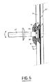
図6および7は、本発明による機械的結合の図であるが、この機械的結合は、このたびは合せガラスに適応している。
【0061】
図6は、板ガラスを壁に固定したのちの機械的結合を表している。ここでの板ガラスの構成は、ケイ酸ソーダ石灰のフロートガラスでできた一枚のいわゆる内板40と、同じ性質のガラスでできたもう一枚のいわゆる外板41とを、ポリビニールブチラールタイプのプラスチック物質でできた中間膜を挟んで、既知の方法で組み立てたものである。(内、外という用語は前の実施例と同じ意味を持っている)。ここでは、内板41にだけさら穴をあけ、前の実施例のように、そのさら穴につば付きガスケット44を介して中空ネジ43を挿入し、ネジ頭を中間膜42の表面に押し当てる。こうして、突き出た要素は外壁上に一つも見えず、このことは特に美観に優れ、また事実上、屋内と屋外の間にコールドブリッジが生じる可能性をすべて排除している。
【0062】
同様に、ここでもヘッド46を備えたロッド要素45と、並びに締付け部品49とナット50があり、ナット50はガスケット51を介して内板40の外面52に押し付けられている。一枚板のガラスに適応した機械的結合(図2)または二重ガラスに適応した機械的結合(図4)との主な違いは、一方では中空ネジ43の寸法にあり、他方では補助部品53が存在していることにある。事実そのとおりここでは、中空ネジはずっと短く、実際上円錐形の頭の部分しか存在しない。さらに、このネジはこの場合でも空洞を画定しているが、しかしこの空洞は、その円形底面だけが、前の実施例のように、圧縮可能なガスケットと接触している。
【0063】
それに反して、空洞の側壁はネジ山を備えており、この中に部品53がねじ込まれ、部品53はナットの形をしており、またそれ自身、円筒形の空洞があけられており、その中にヘッド46が収納されている。こうして、以前の長い中空ネジの代わりに、ネジ頭43を取り付けるが、このネジ頭43は部品53によって延長されている。こうした変更の利点は、合せガラスの組立てとカレンダ加工が容易に実施可能となることであり、このことは図7を参照すればよりよく理解されよう。つまり、図7において枠で囲った部品44および43は、合せガラスの組立て時に取り付けられる部品であり、従ってカレンダ加工時に存在する部品である。
【0064】
ここでネジ43は十分短いので、いかなる要素もカレンダ加工時に板40および41の面から突き出ず、このことはカレンダー加工において、それの通常のパラメートを一つも変えることなく作業できるという理由から極めて有利である。
【0065】
カレンダ加工ののち、機械的結合のためのそれ以外のすべての部品を取り付け、つまり部品53と、ガスケット47と、次にヘッド46を取り付け、ヘッド46は部品53の空洞内に収納され、そうしてから第2ガスケット48と、ナット50およびナット50のガスケット51と、締付け部品49を取り付ける。例えば二重ガラスの場合のように、これらの部品のうち、事実上いったん建築現場においてしか取り付けることのできないものは一部しかない。なぜなら合せガラスは組立て後は部品43及び44を備えているが、突き出た要素を持っておらず、そのままで容易に貯蔵および輸送が可能である。
【0066】
合せガラスに適応させた固定法の変形例では、さら頭を持たないネジを利用することができ、そのネジ頭は、特許出願EP−A−0340089に記載されたとおり、特殊なワッシャを備えており、そのワッシャは空間膜を介して外板ガラスに接着されている。
【0067】
結論として、本発明による関節式結合は極めて多様な種類のガラスに適応させることができる。この結合は実施が容易であり、また焼き付きの危険をすべて減らしているので信頼性が高い。取り付けは一段階でも、あるいは複数の段階に分けて行うこともでき、そのことで特に組立てが複雑になるわけではない。さらに、変位の大きさについての調整を、空洞と関節ヘッドとの間の遊びと、本発明の振り子式関節内に介在する可撓ガスケットの圧縮性とを選択することで、いったん設置したのちの板ガラスの曲げに適応させたならば、その調整は完全に保存される。
【図面の簡単な説明】
【図1】機械的懸架点によって懸架された板ガラスを備える壁の外観を示す図である。
【図2】図1のように懸架された、ある懸架点の高さを中心とする一枚板のガラスの横断面である。
【図3】図2に示したような一枚板のガラスに関して、ある懸架点と同じ高さにおいて機械的結合を組み立てる各ステップを示す概略図である。
【図4】図1のように懸架された、ある懸架点の高さを中心とする二重ガラスの横断面図である。
【図5】図2に示したような二重ガラスに関して、ある懸架点と同じ高さにおいて機械的結合を組み立てる各ステップを示す概略図である。
【図6】図1のように懸架された、ある懸架点の高さを中心とする合せガラスの横断面図である。
【図7】図6に示したような合せガラスに関して、ある懸架点と同じ高さにおいて機械的結合を組み立てる各ステップを示す概略図である。
【符号の説明】
6 ネジ
8 ガスケット
9 空洞
10 ヘッド
11 ロッド
12 ガスケット
13 締付け部品
14 ワッシャ
15 ナット[0001]
[Industrial application fields]
The present invention relates to a mechanical coupling mechanism capable of fixing a plate, in particular a glass sheet element, to a support structure.
[0002]
More specifically, in order to fix the glass element to the support structure, instead of fixing the four sides of the glass element by the surrounding frame, mechanical suspension points are usually arranged at each of the four corners of the glass element, It is related to fixing by the suspension point.
[0003]
[Prior art]
Sheet glass elements thus fixed are known by the term VEA (suspended exterior glass) and are sometimes referred to in English by the term structural glazing.
[0004]
This type of assembly method is almost inconspicuous, thus the entire wall of the building is made up of flat glass elements, some of which are transparent and serve as windowpanes, and the rest are opaque, the entire waist wall Can be fulfilled. When viewed from the outside, such a wall has the smallest surface cut.
[0005]
However, the pursuit of aesthetics should not be done until the reliability of fixation is compromised, and this method of point coupling must calculate various requirements from a mechanical point of view. This connection thus ensures lateral fixation between the glazing element and the support structure, and the support structure is rugged and efficient and in particular supports the weight of the glazing element without risk of breakage. There must be. However, on the other hand, once a flat glass element is mounted, stresses caused by atmospheric conditions such as wind tend to cause the flat glass element to bend against external forces of various properties. Must be able to "respond" without breaking. This bond must therefore allow some bending of the glazing element.
[0006]
Finally, if the glazing element is a double glazing type double glazing and several glass slabs are assembled with a surrounding sealing material with a gas layer in between, the sealing material is actually a structure. Since the weight of the glass plate is transmitted to the sealing material, it is important that excessive shearing force is not applied to the sealing material.
[0007]
Several assembling methods have been proposed for so-called VEA flat glass. Thus, in patent application EP-A-0192472, a fixing method for double glazing is described, in which either a double glazing plate glass is directed to a support structure by simply screwing a screw. Can be tightened. Therefore, there is no special bond between the two glass sheets of the double glass, and there is a possibility that the glass sheet not fixed by this through screw may slide in the vertical direction, which is the peripheral sealing material of the double glass. It seems to exert a great stress on Moreover, even if the above assembly method allows the double glazing to some degree of flexibility once secured, the flexibility is due solely to the presence of a gasket made of a compressible material, This screw is allowed to be displaced in a certain angular direction with respect to a hole made in one or both of the double glasses. This flexibility is therefore very small and at the same time it is not adjustable.
[0008]
In particular, from the patent application EP-A-0506522, a mechanical coupling mechanism that can straighten the positioning of the plate glass element with respect to the structure, or in the case of a double-layer glass, a hole connected to each plate glass of the double-layer glass, A mechanical coupling mechanism is known that allows the centers of all holes to coincide. This application also describes an articulated ball joint mechanism, which is tilted according to a spherical motion about a ball centered on the double glass at the height of its intermediate gas layer. I forgive you. The flexibility of the glass sheet is ensured by this, but the production of the articulated ball joint itself is very troublesome. This is because it is necessary to ensure a perfect fit between the ball head and the hemispherical cavity that houses it, and to eliminate any possibility of seizure between these two parts. Therefore, high precision is required when determining the dimensions of the parts, which leads to very high manufacturing costs.
[0009]
[Problems to be solved by the invention]
Therefore, an object of the present invention is to alleviate the above disadvantages by proposing a new type of mechanical bonding method between so-called VEA glass and its supporting structure. For example, the plate glass is securely suspended from the structure while the flexibility remains in the plate glass, and at the same time, the flexibility is adjusted in a durable manner, and the manufacturing cost and manufacturing complexity are disadvantageous. Can be prevented.
[0010]
The present invention is directed to an assembly in which plates, in particular sheet glass elements, are mechanically coupled onto a support structure, in particular by a suspension along a substantially vertical plane. This coupling is designed to allow the plate to have a flexible movement, the magnitude of the flexible movement being due to the action of an articulating locking mechanism that allows the plate to tilt about its fulcrum on the locking mechanism. Be controlled.
[0011]
The present invention is advantageous when applied to any flat glass element, that is, any of single-sheet glass, laminated glass, and double-glazed double-glazed glass.
[0012]
[Means for Solving the Problems]
In other words, the present invention uses a pendulum motion around a fulcrum instead of a spherical motion centered on a ball, and the pendulum motion generates little or no friction between each mechanical part. Since the surface area is worn or roughened, the position thereof can be known. The joint mechanism according to the invention can be easily manufactured.
[0013]
Furthermore, this mechanism has relatively little wear, and it is particularly advantageous if wear can be provided in the areas where the contact forces generated by the joints are expected to be applied, with appropriate reinforcement.
[0014]
In any case, if there is mild wear in the area, there is no danger and the glass pane is held firmly fixed.
[0015]
A preferred embodiment of an articulating fixation according to the invention comprises at least one element defining a receiving cavity, a support element and at least one clamping / clamping element,
The receiving cavity defining element defines a generally round receiving cavity in the fulcrum region;
The support element comprises a rod, which can be coupled to a support structure, said rod having one of its ends bulging to form a head, the head having rounded sides and a certain amount in the cavity. Suitable for storage with play, once stored, the round side of the head contacts the fulcrum area in the cavity, and the radius of curvature of the round side is smaller than the radius of curvature of the round area of the receiving cavity,
A clamping / clamping element is for holding the head in the receiving cavity. The receiving cavity is advantageously a simple geometry, in particular a rotating surface, and very particularly a cylinder. A swollen head adapted to this type of cavity has a flat front surface, in particular a truncated surface, and side surfaces, which are also rotational surfaces and are substantially convex.
[0016]
This virtually eliminates any potential danger of seizure in the joint. Because the fulcrum area located at the same height as the convex surface of the head (the upper part once the glass element is fixed perpendicular to the wall) is very localized and defined between the receiving cavity and the head This is because the tilt around the fulcrum area is possible by play. As previously mentioned, the friction caused by the joint according to the invention is greatly reduced. Rather, the problem is a localized crushing force between the head and the receiving cavity, which is precisely a different kind of force than a frictional force.
[0017]
Similarly, if some play is to be provided, instead of the ball joint, it is inevitably preceded by a sphere / hemisphere that precedes it to effectively attach the glass sheet to the wall at the construction site. It should be noted that the cavity fitting operation no longer exists. Manufacture is simpler, and the mechanical connection can be divided into a plurality of stages. In particular, it is possible to first attach the sheet glass on the production line itself, and then attach it once at the construction site.
[0018]
It is advantageous to provide a compressible / flexible material, in particular in the form of a gasket, between the bottom surface of the receiving cavity and the front surface of the head of the rod element. The same type of material can likewise be provided around the rod as an inclusion, in particular in the form of a washer, between the clamping element and the rear face of the head of the rod element.
[0019]
These compressible / flexible materials are made of elastomer, which preferably has a shore hardness of between 30 and 80, in particular between 40 and 60. Also important are materials with metallic properties, in particular those of the spring washer type, which are also known by the name of the spring spring washer.
[0020]
By sandwiching such a compressible material, the glass element can be promoted to tilt relative to the fulcrum (or area thereof) on the articulating head. Such a gasket prevents the head from wobbling easily in the receiving cavity, and by being properly crushed locally, it can follow the tilting movement of the glass sheet and the playable parts are made of metal, for example. However, thanks to such a gasket, the tilt in the articulation mechanism according to the invention does not generate unpleasant noise.
[0021]
More precisely, when selecting the geometrical shape of the head of the element with the rod, the shape presents a rotating side and the head comprises two conical parts, which are once installed After being placed on both sides of the flat annular part where the fulcrum of the glass element will be located, a round surface as a whole can thus be constructed by connecting the two cones with a ring. The radius of curvature at this time should be understood as the radius of curvature of the two cones when the two cones are directly connected to each other at the bottom surface. Therefore, it becomes a shape that can be designed in a relatively simple manner, and it is very easy to place it in a receiving cavity that is specifically intended to be cylindrical, both at the plate glass manufacturing site and at the construction site of the building where the plate glass is to be installed.
[0022]
With respect to the receiving cavity, the cavity is preferably defined by a hollow screw, in particular a bald screw, which penetrates all or part of the plate to be fixed. The cavity can and is advantageously lined with a material having a mechanical strength higher than that of the screw body. This further reduces the risk of the cavity being locally crushed by the roughened surface of the joint part, but this roughened surface is due to permanent loads acting on the head and bending of the plate.
[0023]
The so-called clamping element or clamping element may consist of a part of a hollow screw, which is held in place by a nut or retaining nut and around a rod whose one end is the previously defined head It is fitted. The internal contour of this element, for example a trumpet contour, is specifically designed so that the rod has sufficient angular play in this threaded portion.
[0024]
However, the receiving cavity can also be defined by two or more elements, in particular the hollow screw defines the bottom surface of the cavity, and another part is inserted into the cavity, in particular by screwing, and the other part is inserted into the cavity. The side wall may be defined.
[0025]
This type of articulation is certainly specific, but any application of this can be considered depending on the type of plate to be fixed.
[0026]
The simplest form is a single plate, that is, a case where only one glass plate is provided. The mechanical connection at this time comprises a hollow screw, which defines a rotational receiving cavity, and a countersunk screw is also placed in a countersink similarly drilled in the glass sheet, and in some cases The screw head is configured to be flush with one surface of the plate glass by interposing a flanged gasket. This connection also includes a rod, a compressible gasket, and an outer retaining nut, the rod having a head at one end that is fitted with play into the receiving cavity of the screw. , Also held in place by screw-type clamping parts, and a compressible gasket is placed in the cavity to allow the glass pane to tilt easily with respect to the fulcrum on the head, and an outer stop The nut sits on top of the screw and threaded fastener and is pressed against the other side of the glass sheet, and in some cases, a compressible gasket is sandwiched between the glass and the retaining nut.
[0027]
On the other hand, when double glass is the object, it is advantageous to make a circular hole connected to each plate glass constituting the double glass. In this case, it is necessary to seal the hole, and in particular, a metal seal ring is used for sealing, and the seal ring is applied to a double gasket made of butyl and a silicone type elastomer. This connection can then comprise a hollow screw, a nut, a receiving cavity, a rod element, a hollow screw part with a trumpet-like inner contour, a compressible gasket, and an outer retaining nut,
The hollow screw penetrates the double glass and forms the same surface as the surface of the outer glass by countersink, and in some cases sandwiches a flanged gasket,
In some cases, the nut is provided with at least one gasket, and the nut fixes the screw to the double-glazed outer glass,
The receiving cavity is in the screw,
The head of the rod element is for storage in the cavity,
The hollow screw part with a trumpet-like inner contour holds the head in the cavity around the rod by tightening the nut,
The compressible gasket is in the cavity and is intended to facilitate tilting the head around the fulcrum in the cavity;
The outer retaining nut is fitted to the hollow screw portion on the inner plate glass side, and in particular pressed against the sealing ring of the hole drilled in the plate glass, thereby ensuring the tightening of the assembly.
[0028]
Preferably, two eccentric circular rings can be placed in contact with the nuts in a hole drilled in the inner glass sheet of the double glass, so that the nuts pass through the rings through the inner glass sheet. Can be supported.
[0029]
In the case of laminated glass, the mechanical connection according to the invention can be adapted to it, in which case the mechanical connection comprises a hollow screw, which in some cases comprises a flanged joint, the collar A hollow part is similarly fitted in the butt joint, the two parts defining a receiving cavity. The hollow screw preferably passes only through the inner plate of the laminated glass, the mechanical connection also comprises a rod element, the head of the rod element is fitted in the receiving cavity and held by a screw-type clamping part, A gasket made of a compressible material follows the head tilting around the fulcrum of the glass sheet in the cavity. The retaining nut is fitted on the hollow part and the fastening part, and the nut is pressed against the surface of the glass inner plate, and in some cases, a flexible gasket is sandwiched therebetween.
[0030]
Once fixed in this way, the laminated glass looks from the outside and it appears that there are no protruding or visible fixing elements.
[0031]
The present invention also utilizes the previously defined mechanical coupling assembly in the construction of a wide glass screen of the VEA type, as well as having at least one such coupling, the coupling being fixed to the support structure. It is intended for all kinds of glass.
[0032]
The present invention also provides for an assembly of glass sheets arranged side by side to define a building wall, wherein each glass sheet of the assembly has been previously defined by a suspension and, in some cases, by a spade. It covers all glass sheet assemblies that are fixed to a support structure using mechanical bonding, as well as any assembly work related to the bonding.
[0033]
Advantageous features of the present invention will become more apparent from the detailed description of the following non-limiting examples shown in the drawings.
[0034]
【Example】
To simplify the description of the drawings, it should be noted in advance that the dimensional ratios between the various elements depicted in these drawings are not in principle.
[0035]
FIG. 1 shows a partial view of a building wall, which consists of a sheet glass 1, which is separated by a narrow joint 2, each sheet glass 1 being machined into a support structure by
[0036]
FIG. 2 is a cross-sectional view taken along the axis II of FIG. 1 at the height of the
[0037]
There is preferably a transparent sodium silicate lime glass plate 4 having a thickness of at least 8 millimeters, for example 12, 15, 19 millimeters, with countersunk
[0038]
The assembly is tightened with a
[0039]
The coupling according to the invention functions as follows. Once the plate glass is suspended along a substantially vertical plane as shown in FIG. 2, the glass fulcrum on the mechanical bond is approximately located in the annular region of the head 10 and also in the upper part. The fulcrum (or fulcrum region) is represented by the letter P on the drawing. Therefore, the plate glass 4 can tilt in a pendulum manner and in all directions is centered on this point P, and the tilt is realized by the head 10 tilting around this point P in the
[0040]
In FIG. 3, the assembly of the mechanical coupling according to FIG. 2 can be revealed.
[0041]
The screw 6 is slid into the flanged gasket 8 from the
[0042]
The screw 6 is tightened from the
[0043]
The
[0044]
Finally, the head 10 is tightened by rotating the tightening
[0045]
4 and 5 show the mechanical bonding according to the present invention applied to a double glass.
[0046]
FIG. 4 shows the mechanical connection after the plate glass is fixed to the wall.
[0047]
The plate glass here consists of a so-called
[0048]
The two
[0049]
As in the previous embodiment, two
[0050]
The difference from FIG. 2 is that there is an
[0051]
Two eccentric circular rings 32 and 33 are sandwiched between the tightening
[0052]
Tightening of the mechanical connection is realized by a
[0053]
As shown in FIG. 2, once fixed, the double glass can be tilted according to the pendulum motion, with the fulcrum P of the double glass as the center. It will be appreciated that the mechanical bond thus achieved allows the weight of one glass to be transferred to some extent to the other glass, thus not overstressing the double glass perimeter sealant.
[0054]
In FIG. 5, the assembly of the coupling according to FIG. 4 can be clarified.
[0055]
From the side of the
A torus-shaped
[0056]
Next, attach the two
Subsequently, a silicone sealing material 22 is injected toward the
[0057]
Next, with the
Finally, the assembly is tightened by a
[0058]
What is noticed here is that the assembly can be divided into a plurality of stages. Thus, the first stage can be carried out at the production site, i.e. at the processing site of the double glazing itself, the content of which is to carry out all the assembly stages until the eccentric rings 32, 33 are installed, which will be explained below To do.
[0059]
Since all the protruding parts are eliminated, the double glazing is easy to store and transport, and has minimal volume and risk of breakage. The second half of the assembly is then easy, but it is only performed at the construction site.
[0060]
FIGS. 6 and 7 are diagrams of the mechanical connection according to the invention, this time being adapted to a laminated glass.
[0061]
FIG. 6 shows the mechanical connection after the plate glass is fixed to the wall. The structure of the plate glass here is a so-called
[0062]
Similarly, here too, there is a
[0063]
On the other hand, the side walls of the cavity are provided with threads, into which the
[0064]
Here, the screw 43 is short enough so that no element protrudes from the faces of the
[0065]
After calendering, all other parts for mechanical coupling are attached, ie
[0066]
In a variant of the fixing method adapted to the laminated glass, a screw without a head can be used, which screw head is equipped with a special washer as described in patent application EP-A-0340089. The washer is bonded to the outer glass through a space film.
[0067]
In conclusion, the articulated connection according to the invention can be adapted to a very wide variety of glass types. This combination is easy to implement and reliable because it reduces all the risk of seizure. The mounting can be performed in one stage or divided into a plurality of stages, so that the assembly is not particularly complicated. Furthermore, after adjusting the magnitude of the displacement, the play between the cavity and the joint head and the compressibility of the flexible gasket interposed in the pendulum joint of the present invention can be selected. The adjustment is completely preserved if it is adapted to the bending of the glass sheet.
[Brief description of the drawings]
FIG. 1 shows the appearance of a wall with plate glass suspended by a mechanical suspension point.
FIG. 2 is a cross section of a single glass plate centered on the height of a certain suspension point suspended as in FIG.
FIG. 3 is a schematic diagram showing the steps for assembling a mechanical bond at the same height as a suspension point for a single glass sheet as shown in FIG.
FIG. 4 is a cross-sectional view of a double glazing centered on the height of a certain suspension point suspended as in FIG. 1;
FIG. 5 is a schematic diagram showing each step of assembling a mechanical bond at the same height as a suspension point for a double glazing as shown in FIG.
FIG. 6 is a cross-sectional view of a laminated glass that is suspended as shown in FIG. 1 and that is centered on the height of a certain suspension point.
FIG. 7 is a schematic diagram showing the steps for assembling a mechanical bond at the same height as a suspension point for a laminated glass as shown in FIG.
[Explanation of symbols]
6 Screw
8 Gasket
9 Cavity
10 heads
11 Rod
12 Gasket
13 Tightening parts
14 Washer
15 nuts
Claims (18)
支点(P)の領域中に丸い受容空洞(9、24)を画定する少なくとも1つの要素(6、20、43、53)と、
支持構造物につなぐことができるロッド(11、31、45)を備えており、該ロッドがその両端の片方が膨らんでヘッド(10、25、46)を形成し、ヘッドが全体として丸い側面を備えており、またヘッドがある程度の遊びを伴って空洞中に収まっているため、いったん所定の位置に収めたのちは、ヘッドの丸い側面が空洞中の支点(P)の領域と接触するようになっており、丸い側面の曲率半径が受容空洞の丸い領域の曲率半径より小さい、支持要素と、
前記ヘッドを前記受容空洞中に保持するための少なくとも1つの締付け/クランプ要素(13、30、49)とを備えることを特徴とする請求項1に記載の機械的結合用装置。The articulated locking mechanism
At least one element (6, 20, 43, 53) defining a round receiving cavity (9 , 24) in the region of the fulcrum (P);
Rods (11, 31, 45) that can be connected to the support structure, and one end of each of the rods swells to form a head (10, 25, 46), and the head has a round side as a whole. Since the head is contained in the cavity with some play, the round side surface of the head once comes into contact with the region of the fulcrum (P) in the cavity after being put in place. A support element, the radius of curvature of the rounded side is smaller than the radius of curvature of the rounded region of the receiving cavity;
2. A mechanical coupling device according to claim 1, comprising at least one clamping / clamping element (13, 30, 49) for holding the head in the receiving cavity.
中空ネジ(20)は板ガラス(18、19)を貫通し、またさら穴を通して外板ガラス(19)の表面と同一面を形成しており、場合によってはつば付きガスケット(23)を差し挟み、
穴(28)は、場合によっては少なくとも1つのガスケット(29)を備え、そのガスケット(29)が前記ネジ(20)を二重ガラスの外板ガラス(19)に固定し、
受容空洞(24)はネジ(20)内にあり、
ロッド要素(31)のヘッド(25)は空洞(24)の中に収められており、
ラッパ状内部輪郭を持った中空ネジ部分(30)は、ロッド(31)を中心としてヘッド(25)を空洞(24)内に、ナット(28)の締め付けによって保持し、
圧縮可能なガスケット(26、27)は空洞(24)内にあり、ヘッド(25)が空洞(24)内で、板ガラス(18、19)の支点(P)を中心として傾斜するのを許容するためのものであり、
− 止めナット(35)は内板ガラス(18)側の外側にあり、この止めナットを中空ネジ部分(30)上にはめることにより、特にシールリング(21、22)に押し当てることにより、この集合体の締め付けを確実にすることを特徴とする請求項12に記載の機械的結合用装置。The mechanical coupling assembly includes a hollow screw (20), a hole (28), a receiving cavity (24), a rod element (31), and a hollow screw portion (30) having a trumpet inner profile. A compressible gasket (26, 27) and a retaining nut (35);
The hollow screw (20) penetrates the plate glass (18, 19) and forms the same surface as the surface of the outer plate glass (19) through the countersink, and in some cases sandwiches a flanged gasket (23),
The hole (28) optionally comprises at least one gasket (29) that secures the screw (20) to the double glazing outer glass (19);
The receiving cavity (24) is in the screw (20);
The head (25) of the rod element (31) is housed in the cavity (24);
A hollow screw portion (30) having a trumpet-like inner profile holds the head (25) in the cavity (24) around the rod (31) by tightening the nut (28);
The compressible gasket (26, 27) is in the cavity (24) and allows the head (25) to tilt within the cavity (24) about the fulcrum (P) of the glass sheet (18, 19). Is for
The retaining nut (35) is on the outside on the side of the inner glass plate (18), and this assembly is achieved by fitting the retaining nut on the hollow screw part (30), in particular by pressing it against the sealing rings (21, 22). The mechanical coupling device according to claim 12, wherein the body is securely tightened.
Applications Claiming Priority (2)
| Application Number | Priority Date | Filing Date | Title |
|---|---|---|---|
| FR9314338A FR2713258B1 (en) | 1993-11-30 | 1993-11-30 | Mechanical connection between a glazed element and a supporting structure. |
| FR9314338 | 1993-11-30 |
Publications (2)
| Publication Number | Publication Date |
|---|---|
| JPH07197749A JPH07197749A (en) | 1995-08-01 |
| JP3618811B2 true JP3618811B2 (en) | 2005-02-09 |
Family
ID=9453386
Family Applications (1)
| Application Number | Title | Priority Date | Filing Date |
|---|---|---|---|
| JP32129894A Expired - Lifetime JP3618811B2 (en) | 1993-11-30 | 1994-11-30 | Mechanical connection between glass element and support structure |
Country Status (10)
| Country | Link |
|---|---|
| US (1) | US5540514A (en) |
| EP (1) | EP0655543B1 (en) |
| JP (1) | JP3618811B2 (en) |
| AT (1) | ATE154968T1 (en) |
| CZ (1) | CZ291607B6 (en) |
| DE (1) | DE69404016C5 (en) |
| DK (1) | DK0655543T3 (en) |
| ES (1) | ES2106478T3 (en) |
| FR (1) | FR2713258B1 (en) |
| PL (1) | PL177933B1 (en) |
Families Citing this family (86)
| Publication number | Priority date | Publication date | Assignee | Title |
|---|---|---|---|---|
| DE19523674C2 (en) * | 1995-07-03 | 1998-11-05 | Mero Werke Kg | Bracket for plate-shaped components |
| GB9517639D0 (en) * | 1995-08-30 | 1995-11-01 | Pilkington Glass Ltd | Multiple glazing units |
| FR2747424B1 (en) * | 1996-04-12 | 1998-10-30 | Saint Gobain Vitrage | SYSTEM FOR ASSEMBLING BETWEEN A TEMPERED GLASS SHEET AND ANOTHER OBJECT, GLASS SHEET EQUIPPED WITH SUCH A SYSTEM, AND APPLICATION OF SUCH A SHEET |
| WO1998006917A1 (en) * | 1996-08-13 | 1998-02-19 | Fairchild Holding Corp. | Self-aligning fastener system |
| DE19710547B4 (en) * | 1996-11-12 | 2004-10-28 | Joachim Fischbach | Shower cabin with fasteners for holding a glass pane or glass door |
| DE59709687D1 (en) * | 1996-12-19 | 2003-05-08 | Dorma Gmbh & Co Kg | Clamp fitting for fastening glass panes |
| DE19652773C2 (en) * | 1996-12-19 | 1998-11-26 | Dorma Gmbh & Co Kg | Clamp fitting for fastening glass panes |
| EP0863287B1 (en) | 1997-03-06 | 2003-10-15 | Jürgen Pauli | Screwable fastening element for glass panes |
| DE19713678C2 (en) * | 1997-04-03 | 2000-07-13 | Dorma Gmbh & Co Kg | Clamp fitting for fastening glass panes |
| FR2762039B1 (en) * | 1997-04-11 | 1999-06-04 | Saint Gobain Vitrage | ELEMENT GLASS WITH HIGH INSULATING POWER |
| FR2765259B1 (en) | 1997-06-26 | 1999-07-30 | Saint Gobain Vitrage | FACADE, ESPECIALLY GLAZED |
| DE59706558D1 (en) * | 1997-07-28 | 2002-04-11 | Alstom | Ceramic lining |
| DE19749634A1 (en) * | 1997-11-11 | 1999-06-02 | Mero Systeme Gmbh & Co Kg | Bracket for plate-shaped components |
| KR100228599B1 (en) * | 1997-12-26 | 1999-11-01 | 김성만 | Prefabricated pair glass |
| FR2775707A1 (en) * | 1998-03-09 | 1999-09-10 | Laubeuf | Fixing of glass panel on support structure |
| US6042161A (en) * | 1998-05-04 | 2000-03-28 | Reflectolite Products | Variable position lock actuator |
| EA001121B1 (en) * | 1998-06-04 | 2000-10-30 | Дорма Гмбх+Ко.Кг | Device for fixing a glass panel to a support at the side of a building |
| DE19915193C1 (en) * | 1999-04-06 | 2000-11-16 | Dorma Gmbh & Co Kg | Fastening device for a glass plate on a bracket on the building side |
| JP2000108657A (en) * | 1998-10-05 | 2000-04-18 | Nippon Sheet Glass Co Ltd | Vehicle glass plate and vehicle glass window |
| AU1184599A (en) * | 1998-11-10 | 2000-05-29 | Lisus Engineering Pte Ltd | A mounting device |
| DE50002454D1 (en) | 1999-03-26 | 2003-07-10 | Atj Gmbh Systembauteile | FASTENING ELEMENT FOR GLASS PANELS |
| DE19933967C2 (en) * | 1999-07-20 | 2002-11-07 | Marina Orbach | Point fixing system |
| DE19938250C2 (en) * | 1999-08-12 | 2003-06-18 | Vetrotech Saint Gobain Int Ag | Attachment for holding a composite pane |
| DE19938571A1 (en) * | 1999-08-17 | 2001-02-22 | Dorma Gmbh & Co Kg | Clamp fitting for fastening glass panes |
| DE19939172C2 (en) * | 1999-08-20 | 2003-08-28 | Dorma Gmbh & Co Kg | Pointed bracket |
| DE19945196C2 (en) * | 1999-09-21 | 2001-09-20 | Dorma Gmbh & Co Kg | Fastening device for a glass pane |
| DE19945197C1 (en) * | 1999-09-21 | 2001-07-05 | Dorma Gmbh & Co Kg | Fastening device for a glass pane |
| JP2003524715A (en) | 1999-10-04 | 2003-08-19 | オーバーホーファー アルフォンス | Mounting equipment for plates |
| DE29917488U1 (en) * | 1999-10-04 | 2001-02-15 | Oberhofer, Alfons, Wien | Point holder for plates |
| DE19958622C1 (en) * | 1999-12-06 | 2001-08-23 | Dorma Gmbh & Co Kg | Clamp fitting for a glass plate |
| FR2803327B1 (en) * | 2000-01-04 | 2002-04-05 | Laubeuf | FASTENING METHOD AND DEVICE FOR DOUBLE SIDED PANELS |
| DE10048573C1 (en) * | 2000-09-30 | 2002-05-08 | Saint Gobain | Fastening for plates |
| EP1330587A1 (en) | 2000-10-23 | 2003-07-30 | Alfons Oberhofer | Glass pane fixing system |
| AU2002220774A1 (en) * | 2000-11-11 | 2002-05-21 | Saint-Gobain Glass France | Assembly element to be inserted in a bore |
| DE10055983C1 (en) | 2000-11-11 | 2002-09-26 | Eckelt Glas Gmbh Steyr | Assembly element to be placed in bore of glass plate is made with smaller radial dimension than bore outlet in plate outer surface to form slot |
| GB0101280D0 (en) * | 2001-01-18 | 2001-02-28 | Pilkington Plc | Sealed glazing units |
| ES2209568A1 (en) * | 2001-03-15 | 2004-06-16 | Construccions Metal Liques Bellapart, S.A. | System for attaching laminated glass panels |
| DE10114372C2 (en) * | 2001-03-23 | 2003-03-20 | Sws Glasbaubeschlaege Gmbh | point fixing |
| FR2822881A1 (en) | 2001-03-29 | 2002-10-04 | Saint Gobain | Fixing system for panels of fragile material e.g. glass has fastenings with feet attached to underside of panels by adhesive |
| DE10119987C2 (en) * | 2001-04-23 | 2003-10-02 | Dorma Gmbh & Co Kg | Fastening device for fastening sheet-like materials to a rod-like component |
| ATE381657T1 (en) | 2001-10-16 | 2008-01-15 | Alfons Oberhofer | HOLDING SYSTEM FOR PANEL-SHAPED FACADE ELEMENTS |
| FR2831932B1 (en) * | 2001-11-02 | 2004-10-15 | Saint Gobain | MECHANICAL CONNECTION DEVICE FOR SYSTEM FOR ATTACHING ELEMENTS TO A STRUCTURE |
| JP2004149045A (en) * | 2002-10-31 | 2004-05-27 | Honda Motor Co Ltd | Supporting structure of window glass of vehicle |
| FR2849889B1 (en) | 2003-01-15 | 2005-02-18 | Saint Gobain | SYSTEM FOR ASSEMBLING BETWEEN AT LEAST ONE GLASS SHEET AND ANOTHER OBJECT, GLASS SHEET EQUIPPED WITH SUCH A SYSTEM AND APPLICATION OF SUCH A SHEET |
| DE10317081A1 (en) * | 2003-04-13 | 2004-10-28 | Espich, Gerhard, Dr.-Ing. | Connecting element between the bearing element and the plate |
| US7788860B2 (en) * | 2003-07-07 | 2010-09-07 | Zartman Ronald R | Vandal proof system for securing a frangible facing plate to rigid supporting structure by wedging action and a method therefor |
| DE10340720A1 (en) * | 2003-09-04 | 2005-04-07 | Fischerwerke Artur Fischer Gmbh & Co. Kg | Fastening device for producing an anchoring in particular consisting of glass plates |
| CN2737855Y (en) * | 2004-04-29 | 2005-11-02 | 珠海市晶艺玻璃工程有限公司 | Glass curtain wall and roofing rotary disc connecting parts |
| DE102005011741B4 (en) * | 2005-03-11 | 2007-01-18 | Munch, Paul-Jean, Dipl.-Ing. | Attachment for a fitting to a plate-shaped element |
| FR2886322B1 (en) * | 2005-05-27 | 2008-11-28 | Saint Gobain | FIXING DEVICE FOR SUBSTRATES, ESPECIALLY GLASS SUBSTRATES |
| US8186901B2 (en) * | 2006-04-13 | 2012-05-29 | Dura Global Technologies, Llc | Liftglass to strut retention device with built-in locking feature |
| US20080005983A1 (en) * | 2006-07-10 | 2008-01-10 | Epco Architecture Hardware (Taiwan) Corp. | Glass curtain fixing device |
| US20080010921A1 (en) * | 2006-07-12 | 2008-01-17 | Epco Architecture Hardware (Taiwan) Corp. | Glass curtain supporting device |
| WO2008022014A2 (en) * | 2006-08-10 | 2008-02-21 | Research Sciences, Llc | Multimember extended range compressible seal |
| EP1916372B1 (en) * | 2006-10-23 | 2016-12-28 | Hawa Ag | Holding device for panels and separating element |
| US20080196335A1 (en) * | 2007-02-16 | 2008-08-21 | Epco Architecture Hardware (Taiwan) Corp. | Support device for dual-layer glass curtain wall |
| EP2132393B1 (en) | 2007-03-15 | 2017-04-05 | Vetrotech Saint-Gobain (International) AG | Fire-protection composite glass for construction elements such as doors, walls, or windows |
| EP2191091A4 (en) * | 2007-04-02 | 2012-09-12 | Nupress Tools Pty Ltd | An insulated glass unit (igu) and a point fixing apparatus for an igu |
| US8375680B2 (en) * | 2007-04-02 | 2013-02-19 | Nupress Tools Pty Limited | Insulated glass unit (IGU) and a point fixing apparatus for an IGU |
| US20090064612A1 (en) * | 2007-09-12 | 2009-03-12 | Carlson Peter M | Multi-layer construction panel system |
| WO2009154805A1 (en) * | 2008-06-20 | 2009-12-23 | Hunter Douglas Industries B. V. | Low-profile fastener assemblies, panel mounting systems,and methods |
| US8171690B2 (en) * | 2008-05-28 | 2012-05-08 | 3Form, Inc. | Countersunk fastener assemblies, panel mounting systems, and methods |
| US7603820B1 (en) * | 2008-09-10 | 2009-10-20 | Taiwan Dali Aurora Enterprise Co., Ltd. | Glass pane connector |
| US8595995B2 (en) * | 2008-09-23 | 2013-12-03 | Architectural Glass And Aluminum Corporation, Inc. | Method of assembling an electrical raceway for building integrated solar PV system |
| US8393601B2 (en) | 2008-10-04 | 2013-03-12 | Applied Concepts Aircraft Solutions, Inc. | Vibration isolation fastener insert |
| US20100126087A1 (en) * | 2008-11-13 | 2010-05-27 | Joe Brescia | Plank Based Photovoltaic Conversion System |
| GB0902627D0 (en) * | 2009-02-17 | 2009-04-01 | Pilkington Group Ltd | Improvements in or relating to structural glass assemblies |
| US8732940B2 (en) * | 2009-03-12 | 2014-05-27 | Clean Energy Solutions, Inc. | System and method for mounting photovoltaic panels |
| US8584406B2 (en) | 2009-05-20 | 2013-11-19 | Sunpower Corporation | Hole-thru-laminate mounting supports for photovoltaic modules |
| BE1019123A3 (en) | 2009-12-23 | 2012-03-06 | Agc Glass Europe | FIXING SYSTEM, INSULATION, GLAZING ON A CARRIER STRUCTURE. |
| TWI403045B (en) * | 2010-07-09 | 2013-07-21 | Ind Tech Res Inst | Solar wiring device and solar photovoltaic module with the wiring device |
| US20120181402A1 (en) * | 2011-01-13 | 2012-07-19 | 3Form, Inc. | Adjustable bushing assemblies, panel mounting systems, and methods |
| GB201113065D0 (en) * | 2011-07-29 | 2011-09-14 | Airbus Uk Ltd | Aircraft glazing attachment |
| US10457376B1 (en) * | 2012-05-08 | 2019-10-29 | Airmedic | Aircraft stretcher connector |
| US9140279B2 (en) | 2012-09-25 | 2015-09-22 | The Young Engineers, Inc. | Magnetic mount |
| CN103863067B (en) * | 2014-03-04 | 2016-03-23 | 江苏铁锚玻璃股份有限公司 | Can quick-replaceable high speed train windshield production method and windshield |
| FR3024506B1 (en) * | 2014-07-30 | 2016-07-29 | Saint Gobain | GLAZING COMPRISING A PION AND METHOD FOR MANUFACTURING GLAZING. |
| US10562274B1 (en) * | 2016-02-22 | 2020-02-18 | Apple Inc. | Glass fastening and sealing systems |
| CN106760078B (en) * | 2017-01-11 | 2020-03-20 | 广东坚朗五金制品股份有限公司 | Glass curtain wall clamp |
| PL239746B1 (en) * | 2017-11-23 | 2022-01-03 | Boguslaw Szarejko | A joint for fastening the facade insulating glass units |
| RU188235U1 (en) * | 2019-01-31 | 2019-04-03 | Ашот Беджанович Оганесян | Glass holder |
| RU194249U1 (en) * | 2019-10-01 | 2019-12-04 | Ашот Беджанович Оганесян | Glass holder |
| CN110984443B (en) | 2019-12-11 | 2022-02-15 | 广东坚朗五金制品股份有限公司 | Connecting device |
| CN111075098B (en) * | 2019-12-30 | 2021-10-01 | 成都劲启家居有限公司 | Ceiling method for preventing ceiling board from shaking |
| DE102020104096A1 (en) | 2020-02-17 | 2021-08-19 | Arnold Hillerzeder | Point holder for flat elements |
| CN112282382B (en) * | 2020-10-29 | 2021-08-24 | 北京城建六建设集团有限公司 | Multi-curved-surface special-shaped film mounting structure and mounting method |
Family Cites Families (7)
| Publication number | Priority date | Publication date | Assignee | Title |
|---|---|---|---|---|
| US1410004A (en) * | 1921-02-16 | 1922-03-21 | Flannery Bolt Co | Stay-bolt structure |
| US4431353A (en) * | 1981-05-28 | 1984-02-14 | Russell Burdsall & Ward Corporation | Fastener assembly |
| FR2580342B1 (en) * | 1985-04-16 | 1988-05-13 | Dutton Hugh | MECHANICAL ATTACHMENT OF PLATE MATERIALS TO A VERTICAL SUPPORT STRUCTURE OF SAID MATERIALS |
| US4666330A (en) * | 1985-12-04 | 1987-05-19 | Tuthill Corporation | Ball joint assembly |
| FR2630766B1 (en) * | 1988-04-28 | 1992-07-24 | Saint Gobain Vitrage | GLASS ELEMENT FOR CURTAIN FACADE |
| FR2674554B1 (en) * | 1991-03-29 | 1998-08-21 | Saint Gobain Vitrage Int | SYSTEM FOR FIXING A GLASS PLATE. |
| AT396614B (en) * | 1992-01-17 | 1993-10-25 | Brueder Eckelt & Co Glastech | INSULATED GLASS ELEMENT |
-
1993
- 1993-11-30 FR FR9314338A patent/FR2713258B1/en not_active Expired - Lifetime
-
1994
- 1994-11-25 PL PL94305997A patent/PL177933B1/en unknown
- 1994-11-25 AT AT94402709T patent/ATE154968T1/en active
- 1994-11-25 ES ES94402709T patent/ES2106478T3/en not_active Expired - Lifetime
- 1994-11-25 DE DE69404016T patent/DE69404016C5/en not_active Expired - Lifetime
- 1994-11-25 DK DK94402709.3T patent/DK0655543T3/en active
- 1994-11-25 EP EP94402709A patent/EP0655543B1/en not_active Expired - Lifetime
- 1994-11-29 CZ CZ19942946A patent/CZ291607B6/en not_active IP Right Cessation
- 1994-11-30 JP JP32129894A patent/JP3618811B2/en not_active Expired - Lifetime
- 1994-11-30 US US08/351,132 patent/US5540514A/en not_active Expired - Lifetime
Also Published As
| Publication number | Publication date |
|---|---|
| JPH07197749A (en) | 1995-08-01 |
| DE69404016D1 (en) | 1997-08-07 |
| FR2713258A1 (en) | 1995-06-09 |
| DE69404016T2 (en) | 1998-02-19 |
| EP0655543B1 (en) | 1997-07-02 |
| CZ294694A3 (en) | 1995-06-14 |
| EP0655543A1 (en) | 1995-05-31 |
| US5540514A (en) | 1996-07-30 |
| FR2713258B1 (en) | 1996-02-09 |
| CZ291607B6 (en) | 2003-04-16 |
| PL305997A1 (en) | 1995-06-12 |
| PL177933B1 (en) | 2000-01-31 |
| DK0655543T3 (en) | 1998-02-16 |
| DE69404016C5 (en) | 2006-08-24 |
| ES2106478T3 (en) | 1997-11-01 |
| ATE154968T1 (en) | 1997-07-15 |
Similar Documents
| Publication | Publication Date | Title |
|---|---|---|
| JP3618811B2 (en) | Mechanical connection between glass element and support structure | |
| EP0201212B1 (en) | Architectural mounting for plate glass | |
| US6442911B2 (en) | Building glass facade of a building, clamping arrangement in a facade, and a clamping arrangement for clamping a building glass pane in a facade | |
| JP3270507B2 (en) | Vertical plate connecting device in building | |
| US7213375B2 (en) | Sealed glazing units | |
| CA2011991C (en) | Device for mounting insulating double-glazing onto a fixed frame | |
| JPH06193171A (en) | Support structure of glass pane | |
| US20020031398A1 (en) | Attachment device for mounting a glass pane fixedly to a structure, such as a building and a facade having attachment devices for mounting glass panes fixedly to a structure, such as a building | |
| JP3669026B2 (en) | Laminated glass mounting structure | |
| JP2006517270A (en) | System enabling assembly between at least one glass plate and another object, glass plate provided with such a system, and use of such glass plate | |
| JP3346525B2 (en) | Glass plate support structure | |
| JP2000104456A (en) | Double glazing and support structure thereof | |
| JP3675700B2 (en) | Glass plate support bracket and support structure | |
| JP3183803B2 (en) | Glass plate support | |
| JP4246105B2 (en) | Multi-layer glass and its supporting structure | |
| JP2000110284A (en) | Tabular material supporting structure | |
| JP3152383B2 (en) | Multi-layer glass plate and its supporting structure | |
| JPH07331780A (en) | Support structure of pane | |
| JP3381904B2 (en) | Plate-shaped support structure | |
| JPH11172822A (en) | Support structure for glass plate | |
| JP2000110285A (en) | Tabular material support structure | |
| JPH09221860A (en) | Metal fitting for wall panel | |
| JPH09291629A (en) | Glass plate supporting metal fitting and supporting structure | |
| JP2003129600A (en) | Glass plate bearing structure and method for constructing the same | |
| JPH0637409U (en) | Glass plate support bracket |
Legal Events
| Date | Code | Title | Description |
|---|---|---|---|
| A131 | Notification of reasons for refusal |
Free format text: JAPANESE INTERMEDIATE CODE: A131 Effective date: 20040309 |
|
| A521 | Request for written amendment filed |
Free format text: JAPANESE INTERMEDIATE CODE: A523 Effective date: 20040609 |
|
| A131 | Notification of reasons for refusal |
Free format text: JAPANESE INTERMEDIATE CODE: A131 Effective date: 20040629 |
|
| A521 | Request for written amendment filed |
Free format text: JAPANESE INTERMEDIATE CODE: A523 Effective date: 20040929 |
|
| TRDD | Decision of grant or rejection written | ||
| A01 | Written decision to grant a patent or to grant a registration (utility model) |
Free format text: JAPANESE INTERMEDIATE CODE: A01 Effective date: 20041026 |
|
| A61 | First payment of annual fees (during grant procedure) |
Free format text: JAPANESE INTERMEDIATE CODE: A61 Effective date: 20041111 |
|
| R150 | Certificate of patent or registration of utility model |
Free format text: JAPANESE INTERMEDIATE CODE: R150 |
|
| FPAY | Renewal fee payment (event date is renewal date of database) |
Free format text: PAYMENT UNTIL: 20071119 Year of fee payment: 3 |
|
| FPAY | Renewal fee payment (event date is renewal date of database) |
Free format text: PAYMENT UNTIL: 20081119 Year of fee payment: 4 |
|
| FPAY | Renewal fee payment (event date is renewal date of database) |
Free format text: PAYMENT UNTIL: 20091119 Year of fee payment: 5 |
|
| FPAY | Renewal fee payment (event date is renewal date of database) |
Free format text: PAYMENT UNTIL: 20091119 Year of fee payment: 5 |
|
| FPAY | Renewal fee payment (event date is renewal date of database) |
Free format text: PAYMENT UNTIL: 20101119 Year of fee payment: 6 |
|
| FPAY | Renewal fee payment (event date is renewal date of database) |
Free format text: PAYMENT UNTIL: 20111119 Year of fee payment: 7 |
|
| FPAY | Renewal fee payment (event date is renewal date of database) |
Free format text: PAYMENT UNTIL: 20111119 Year of fee payment: 7 |
|
| FPAY | Renewal fee payment (event date is renewal date of database) |
Free format text: PAYMENT UNTIL: 20121119 Year of fee payment: 8 |
|
| FPAY | Renewal fee payment (event date is renewal date of database) |
Free format text: PAYMENT UNTIL: 20121119 Year of fee payment: 8 |
|
| FPAY | Renewal fee payment (event date is renewal date of database) |
Free format text: PAYMENT UNTIL: 20131119 Year of fee payment: 9 |
|
| R250 | Receipt of annual fees |
Free format text: JAPANESE INTERMEDIATE CODE: R250 |
|
| EXPY | Cancellation because of completion of term |