JP3611753B2 - Reinforced beams and unit buildings - Google Patents
Reinforced beams and unit buildings Download PDFInfo
- Publication number
- JP3611753B2 JP3611753B2 JP23461199A JP23461199A JP3611753B2 JP 3611753 B2 JP3611753 B2 JP 3611753B2 JP 23461199 A JP23461199 A JP 23461199A JP 23461199 A JP23461199 A JP 23461199A JP 3611753 B2 JP3611753 B2 JP 3611753B2
- Authority
- JP
- Japan
- Prior art keywords
- large space
- reinforcing beam
- building
- stiffener
- building units
- Prior art date
- Legal status (The legal status is an assumption and is not a legal conclusion. Google has not performed a legal analysis and makes no representation as to the accuracy of the status listed.)
- Expired - Fee Related
Links
Images


Landscapes
- Rod-Shaped Construction Members (AREA)
Description
【0001】
【発明の属する技術分野】
本発明は、補強梁及びこの補強梁を用いたユニット式建物に関する。
【0002】
【背景技術】
従来より、工場で製造した箱状の建物ユニットを、建築現場で複数組合わせて建築されるユニット式建物が利用されている。
ユニット式建物を形成する建物ユニットとしては、四隅の柱の上下端を天井梁および床梁で連結した直方体状の骨組みを有するものが一般的である。このような建物ユニットを複数組み合わせて一つの居室を造る場合、その中央部は複数の柱が組み合わされる状態となり広い空間を形成できない。
このため、建物ユニットの柱の一部を省略したユニット(以下、大空間用建物ユニットと呼ぶ)を用いて広い空間を造り出すという方法が採られている。
ところが、この大空間用建物ユニットを用いると、建物ユニットの剛性が低下し、上方に載置される建物ユニット等の荷重を支持しきれなくなる可能性がある。これを解決するため、柱の一部が省略された部分を中央にして、その両側に配置される柱の上端を連結する2スパン分の補強梁が設けられることがある(特開平8−277580号公報参照)。
【0003】
【発明が解決しようとする課題】
ユニット式建物を施工する際には、隣接する各建物ユニットを位置決めする必要がある。通常の建物ユニットにおいては、突き合わされた各コーナー部に各々設けられた位置決め用のピンに、それに対応した孔が形成された一枚の金属板を上から差し込むことにより行われている。したがって、突き合わされた各コーナー部間の隙間は金属板で覆われることになる。しかし、前述の大空間用建物ユニットを用いた施工においては、補強梁が複数の大空間用建物ユニットに跨って取り付けられるため、前述の位置決め技術をそのまま使用できないという問題がある。
【0004】
本発明の第一の目的は、隣接する大空間用建物ユニットの位置決めが容易な補強梁を提供することにある。
また、本発明の第二の目的は、上述した補強梁を用いたユニット式建物を提供することにある。
【0005】
【課題を解決するための手段】
本願発明は、四隅の柱の上下端を天井梁及び床梁で連結した直方体状の骨組みを有する通常の建物ユニットと、この通常の建物ユニットの骨組みから一本の柱を省略した複数の大空間用建物ユニットとを含んで形成されたユニット式建物の内部に、柱のない大空間を形成するために複数の大空間用建物ユニットの柱を省略した部位を隣接配置した際に、前記隣接した大空間用建物ユニット間を連結補強するための補強梁であって、隣接した大空間用建物ユニットに跨り大空間用建物ユニットの梁に沿って設けられる長尺状の補強梁本体と、この補強梁本体の長手方向に直交配置されるスチフナと、これら補強梁本体の側面とスチフナの側面との両方に跨るように、これらの側面の上下方向のほぼ中央位置に水平方向に突出して取り付けられ、隣接する大空間用建物ユニット同士の位置決めを行うシアープレートとを備え、このシアープレートは、隣接した大空間用建物ユニットの柱を省略した部位の上面において、柱を省略した部位を位置決めピンを介して位置決めすることを特徴とする補強梁である。
【0015】
【発明の実施の形態】
以下、本発明の一実施の形態を図面に基づいて説明する。
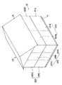
図1には、本発明の一実施形態に係るユニット式建物10が示されている。ユニット式建物10は、基礎11の上に載置される建物本体12及び屋根13を備えたものである。
建物本体12は、箱状に形成された複数の建物ユニット120を組合わせて造られたものである。
【0016】
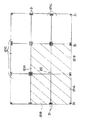
ユニット式建物10の一階部分は、図2に示されるように、建物本体12の外周縁に沿って四隅の柱31を全て有する通常の建物ユニット121CがL字形状に5個並べて配置され、このL字の入隅部分に柱31の一本が省略された大空間用建物ユニット121A、121Bが各々二つずつ配置されることによって形成されている。
ユニット式建物10の二階部分も下階と同様に、L字形状に配置された通常の建物ユニット122C及び大空間用建物ユニット122A、122Bにより形成されている(図1参照)。
【0017】
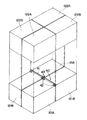
大空間用建物ユニット121A(122A)は、図3に示されるように、角柱状に形成された三本の金属製の柱31の上下端が金属製の天井梁32および床梁33で連結されている。また、柱31が省略された一辺には、取り外し可能な仮柱37が設けられ直方体状の骨組み30を構成している。ここにおいて、天井梁32は、断面C型に形成された金属製の短辺天井梁32A及び同様の長辺天井梁32Bの二種類からなる。一方、床梁33も断面C型に形成された金属製の短辺床梁33Aおよび同様の長辺床梁33Bの二種類からなる。
対向する長辺天井梁32Bの間には、木製柱状の天井小梁34が複数条架け渡され、この天井小梁34に木製板状の天井面材36が固定されている。また、対向する長辺床梁33Bの間には、図示しない根太が複数条架け渡され、この上に床を形成する木製板状の床面材35が貼られている。また、もう一方の大空間用建物ユニット121B(122B)は、大空間用建物ユニット121Aの仮柱37が柱31とされ、その隣に位置する二本の柱31のうちの一本が省略されたものである他は同一構成である。すなわち、両者は、いわゆる勝手違いな形状とされている。
なお、一階を形成する通常の建物ユニット121C及び二階を形成する通常の建物ユニット122Cについては、四隅の柱31を全て備えた点のみが図3に示す大空間用建物ユニット121Aと異なり、その他の構成は同一である。
【0018】
図2において、一点鎖線のハッチングで示される各々2個ずつの大空間用建物ユニット121A及び121Bは、各々の柱省略コーナー部同士が寄せ合わされて柱省略接合部20を形成する状態で隣接配置されている。
これにより、大空間用建物ユニット121A、121Bにより形成される居室の中心部分には、柱31等の障害物が何ら存在しない広い空間が形成される。
【0019】
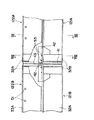
このような大空間用建物ユニット121A、121Bにおいて、その寄せ合わされた短辺天井梁32Aの間には、図4に示されるように、板状に形成された長尺状の金属製補強梁40が短辺天井梁32Aに沿うように設置され、これにより隣接する大空間用建物ユニット121A、121Bが連結補強されている。
図5から図9を用いて補強梁40の構成をより詳細に説明する。補強梁40は、柱省略接合部20の補強に寄与する長尺、板状の補強梁本体41を備え、この補強梁本体41の両側面には、補強梁本体41の長手方向に直交するように平面矩形に形成された金属製板状のスチフナ43が取り付けられている。柱省略接合部20において、スチフナ43の両側面に、大空間用建物ユニット121A、121Bの位置決めに用いる金属製シア−プレート42が、補強梁本体41の長手方向に沿って、補強梁本体41の上下方向のほぼ中央位置に取り付けられている。ここにおいて、シア−プレート42は、矩形金属板の二辺が折り曲げられたものであり、直交する二つの断面がそれぞれL字形状に形成されている。そして、その一辺が補強梁本体41に当接して溶接等により固定され、他辺が同様にしてスチフナ43に固定されている。これにより柱省略接合部20において、補強梁本体41、シア−プレート42、スチフナ43の三部材が各々直交、かつ、一体として形成される。
【0020】
一方、補強梁本体41の両端部に位置するシア−プレート42は、矩形金属板の一辺のみが断面L字形状に折り曲げられて形成され、この一辺が補強梁本体41に当接して溶接等により固定されている。これら各位置のシア−プレート42は、各大空間用建物ユニット121A、121Bにおいて、突き合わされる各短辺天井梁32Aの両端部分に対応する位置に全部で8個設けられている。
【0021】
また、上階の大空間用建物ユニット122A、122Bの短辺床梁33Aの上部には複数個の金属製ナット52が補強梁本体41の長手方向に沿って一列に並ぶように設けられている。このナット52に変形防止手段である金属製の変形防止ボルト51が螺合され、これらのナット52及び変形防止ボルト51により補強梁変形防止構造50が構成される(図5、図9参照)。この変形防止ボルト51の先端部は、補強梁本体41にその両側から互いに対向して当接される(図9参照)。
【0022】
このように構成された補強梁40と、上階の大空間用建物ユニット122A、122Bの短辺床梁33Aと、下階の大空間用建物ユニット121A、121Bの短辺天井梁32Aとの接合手順を説明する。
工場で大空間用建物ユニット121A(122A)、121B(122B)、を複数製造した後、建築現場に搬送する。この際、搬送時における大空間用建物ユニット121A(122A)、121B(122B)の変形を防止するために、柱31が省略されたコーナー部には仮柱37が設けられる。
一階部分を構成する大空間用建物ユニット121A、121Bを隣接配置し、短辺天井梁32Aに補強梁40を載置する(図4、図6参照)。この際、短辺天井梁32Aの柱省略コーナー部に設けられている位置決めピン53を、柱省略接合部20における各シア−プレート42に形成された孔421に差し込む。これにより、大空間用建物ユニット121A、121Bの位置決めが同時に行われることになる(図5、図6参照)。この状態では、補強梁本体41の略下半分が短辺天井梁32Aの間に挟まれ、スチフナ43の略下半分が長辺天井梁32Bの間に挟まれることになる(図6参照)。
【0023】
その後、二階を構成する大空間用建物ユニット122A、122Bを下階の大空間用建物ユニット121A、121Bの上に載置する。この際、前述の孔421を挿通し、突出した位置決めピン53の先端部が、上階の短辺床梁33Aの柱省略コーナー部下面に設けられた孔(図示省略)に挿入される。さらに、シア−プレート42に設けられた孔422を通じて上下の各大空間用建物ユニット122A(122B)と121A(121B)とを締結ボルト54及び締結ナット55で固定する(図5参照)。
その後、短辺床梁33Aに設けられた複数のナット52に変形防止ボルト51を螺合し、この変形防止ボルト51の先端を補強梁本体41の両側から補強梁本体41に当接させる。これにより、補強梁40と、上階大空間用建物ユニット122A、122Bの短辺床梁33Aと、下階大空間用建物ユニット121A、121Bの短辺天井梁32Aとの接合が完了する。
ここで、仮柱37を取り外し、居室内に柱31等の障害物が何ら存在しない大空間が形成される。
【0024】
上述のような本実施形態によれば、次のような効果がある。
(1)位置決めに用いるシア−プレート42が補強梁本体41に予め取り付けられているから、大空間用建物ユニット121A、121Bにおける柱省略接合部20の補強と、隣接する大空間用建物ユニット121A、121Bとの位置決めを同時に行うことができる。
(2)補強梁本体41に直交配置されたスチフナ43により、補強梁40の強度を向上させることができる。したがって、補強梁本体41をより薄して軽量化を図ることができるとともに、材料コストの削減が可能となる。
【0025】
(3)スチフナ43をシア−プレート42で挟み込むことにより、スチフナ43の接合強度が向上できる。また、補強梁本体41、スチフナ43、シア−プレート42の三部材が互いに直交して接合されて一体となることから、補強梁40全体の強度が向上できる。
(4)シア−プレート42の断面がL字形状に形成されているため、その取り付けが容易になる。また、補強梁本体41とシア−プレート42との接合面積がある程度確保できるから、それらの接合強度を大きくできる。
(5)柱省略接合部20におけるシア−プレート42は、二辺が折り曲げられているから、補強梁本体41との接合強度を向上できるだけでなく、スチフナ43との接合強度も向上させることができる。したがって、補強梁40全体の強度がより大きくできる。また、大空間用建物ユニット121A、121Bの位置決めがより確実にできる。
【0026】
(6)ナット52及び変形防止ボルト51からなる補強梁変形防止構造50を用いているから、補強梁本体41が薄い板状のものでも、そのわん曲が確実に防止できる。
(7)変形防止手段は、変形防止ボルト51を用いた非常に簡単なものであり、その製造コストが安価にできる。
(8)変形防止ボルト51は、補強梁本体41を挟んで対向配置されていることから、両側から補強梁本体41を確実に押さえ、そのわん曲を防止できる。
【0027】
(9)変形防止ボルト51は、補強梁本体41の長手方向に沿って複数配置されていることから、補強梁40が長くても、そのわん曲を確実に防止できる。したがって、より広い空間を有する居室を形成できる。
(10)変形防止ボルト51は、短辺床梁33Aに固定されたナット52に螺合されるものであるから、その取り付けが容易である。また、補強梁本体41に変形防止手段を設けるものではないから、補強梁本体41の基本構造に従来のものを採用できる。したがって、その開発コストが削減できる。
(11)シア−プレート42が補強梁本体41に設けられているから、ユニット式建物10の施工の際に隣接する大空間用建物ユニット121A、121B等の位置決め作業が容易にできる。また、補強梁本体41、シア−プレート42、スチフナ43の三部材が一体となり補強梁40の強度を向上させていること、かつ、補強梁変形防止構造50を用いていることから、より軽量化された補強梁40を用いて剛性の高いユニット式建物10を得ることができる。
【0028】
なお、本発明は前記実施形態に限定されるものではなく、本発明の目的を達成できる範囲での変形、改良は、本発明に含まれるものである。
【0029】
前記実施形態において、補強梁40は、大空間用建物ユニット121A、121Bの短辺天井梁32Aを補強していたが、これに限らず、長辺天井梁32Bを補強するものでもよい。ただし、補強梁40を短辺天井梁32Aを補強するものとすることで、長辺天井梁32Bを補強する場合より高い剛性が確保できるので望ましい。また、補強梁本体41は板状に形成されていたが、これに限らず、柱状あるいは扁平ブロック状等、他の形状でもよい。ただし、板状にすることで補強梁本体41を軽量化することができ望ましい。一方、柱状等にすることで各大空間用建物ユニット121A、121Bの間が広くなり、その分だけ広い空間を持つ居室を形成できる。
【0030】
また、図10から図12の第1変形例ないし第3変形例に示すように、補強梁本体41に補強部材45、46、47を接合したものを用いてもよい。このようにすることで、補強梁40の断面係数が向上し、補強梁40の強度が向上して好ましい。
なお、補強部材45、46、47は、補強梁本体41の長手方向に沿って、補強梁本体41と同じ長さ分だけ取り付けてもよいが、小片に分けて、適宜な位置に任意の数だけ取り付けてもよい。
【0031】
前記実施形態において、シア−プレート42は、矩形金属板の少なくとも一辺が折り曲げられていたが、折り曲げない矩形板状のものをそのまま用いてもよい。ただし、折り曲げることで、補強梁本体41及びスチフナ43との接合面が大きくでき、各部材の接合強度を大きくできるので好ましい。また、その形状も矩形である必要はなく、例えば台形等でもよく、位置決めできる形状であればよい。シア−プレート42は、各々二個ずつ合計四個の大空間用建物ユニット121A、121Bの位置決めを行うため、補強梁本体41の両側に設けられていたが、これに限らず、各々一個ずつの大空間用建物ユニット121A、121Bの位置決めに用いてもよく、この場合には、補強梁本体41の片面のみにシア−プレート42が設けられることになる。
【0032】
前記実施形態において、スチフナ43は平面矩形状に形成されていたが、これに限ることなく、例えば台形、三角形等の他の形状でもよい。
また、補強梁40の構成部材は、全て金属製のものを用いていたが、他の材質でも補強効果を奏するものであればよい。
【0033】
前記実施形態において、補強梁変形防止構造50は、ナット52と変形防止ボルト51とを用いたものであるが、これに限らず、補強梁本体41のわん曲を防止できる構造であればよい。
補強梁変形防止構造50は補強梁本体41の長手方向に沿って一列に設けられているが、これに限らず、二列以上でもよい。また、前記実施形態および各変形例において、補強梁変形防止構造50は補強梁本体41の両側に設けられているが、これに限らず、片側でもよい。ただし、両側に設けることで補強梁本体41の変形を確実に防止できるので好ましい。
【0034】
【発明の効果】
本発明によれば、以下のような効果がある。すなわち、位置決めに用いるシアープレートが補強梁本体に取り付けられているから、大空間用建物ユニットの柱省略接合部の補強と隣接する各大空間用建物ユニット間の位置決めとを同時に行うことができる。したがって、補強梁を用いるユニット式建物の施工作業が簡易になる。
また、補強梁本体の長手方向に対して直交して配置されるスチフナにより補強梁の強度を向上させることができる。したがって、補強梁本体をより薄くすることが可能になり、補強梁の軽量化が図れるとともに、材料コストの削減が可能となる。そして、スチフナをシアープレートで挟み込むことにより、スチフナの強度が向上できる。また、補強梁本体、スチフナ、シアープレートの三部材が互いに接合され一体となることから、補強梁全体の強度が向上できる。
更に、シアープレートの断面がL字形状に形成されているため取り付けが容易になる。また、補強梁本体とシアープレートとの接合面積がL字の一辺により確保できるから、それらの接合強度を大きくできる。そして、補強梁の効果を達成できるユニット式建物が得られる。すなわち、その施工の際に位置決めが作業が容易にでき、かつ、簡易な構造の補強梁で剛性の高いユニット式建物を得ることができる。
【図面の簡単な説明】
【図1】本発明の一実施形態に係るユニット式建物を示す全体斜視図である。
【図2】前記実施形態に係る一階部分の概略平面図である。
【図3】前記実施形態に係る大空間用建物ユニットを示す斜視図である。
【図4】前記実施形態に係る大空間用建物ユニットの分解斜視図である。
【図5】前記実施形態に係る補強梁及び大空間用建物ユニットの柱省略接合部を示す部分分解斜視図である。
【図6】前記実施形態に係る柱省略接合部における一部を切り欠いた部分上面図である。
【図7】前記実施形態に係る柱省略接合部における一部を切り欠いた部分側面図である。
【図8】図7におけるVIII−VIII線に沿う一部を切り欠いた断面図である。
【図9】図7におけるIX−IX線に沿う端面図である。
【図10】本発明の第1変形例を示す図9相当の端面図である。
【図11】本発明の第2変形例を示す図9相当の端面図である。
【図12】本発明の第3変形例を示す図9相当の端面図である。
【符号の説明】
10 ユニット式建物
121C、122C 通常の建物ユニット
121A、121B、122A、122B 大空間用建物ユニット
20 柱省略接合部
30 骨組み
31 柱
32 天井梁
33 床梁
40 補強梁
41 補強梁本体
42 シア−プレート
43 スチフナ
50 補強梁変形防止構造
51 変形防止ボルト
52 ナット[0001]
BACKGROUND OF THE INVENTION
The present invention relates to a reinforcing beam and a unit type building using the reinforcing beam.
[0002]
[Background]
Conventionally, unit type buildings constructed by combining a plurality of box-shaped building units manufactured in a factory at a construction site are used.
As a building unit forming a unit type building, one having a rectangular parallelepiped frame in which upper and lower ends of pillars at four corners are connected by a ceiling beam and a floor beam is generally used. When one living room is constructed by combining a plurality of such building units, the central portion is in a state in which a plurality of pillars are combined, and a wide space cannot be formed.
For this reason, a method of creating a wide space using a unit (hereinafter referred to as a large space building unit) in which some of the pillars of the building unit are omitted is employed.
However, when this large space building unit is used, there is a possibility that the rigidity of the building unit is lowered and the load of the building unit or the like placed above cannot be supported. In order to solve this problem, there are cases where reinforcing beams for two spans are provided to connect the upper ends of the pillars arranged on both sides of the part where the part of the pillars is omitted (Japanese Patent Laid-Open No. 8-277580). No. publication).
[0003]
[Problems to be solved by the invention]
When constructing a unit type building, it is necessary to position each adjacent building unit. In a normal building unit, a single metal plate in which a hole corresponding to the positioning pin provided at each corner portion that is abutted is inserted from above. Therefore, the gaps between the corner portions that are abutted are covered with the metal plate. However, in the construction using the above-described large space building unit, there is a problem that the above-described positioning technique cannot be used as it is because the reinforcing beam is attached across a plurality of large space building units.
[0004]
A first object of the present invention is to provide a reinforcing beam that allows easy positioning of adjacent large space building units.
The second object of the present invention is to provide a unit type building using the above-mentioned reinforcing beam.
[0005]
[Means for Solving the Problems]
The present invention relates to a normal building unit having a rectangular parallelepiped frame in which upper and lower ends of columns at four corners are connected by a ceiling beam and a floor beam, and a plurality of large spaces in which one column is omitted from the frame of the normal building unit When a portion in which the pillars of a plurality of large space building units are omitted is arranged adjacent to the inside of the unit type building formed including the building unit, a plurality of large space building units are adjacent to each other. a reinforcing beam for coupling reinforce the inter large space for building unit, the elongated reinforcing beam body provided along the beams large space for building units span large space for building units adjacent, the reinforcing A stiffener arranged orthogonally to the longitudinal direction of the beam body, and attached to projecting in the horizontal direction at a substantially central position in the vertical direction of these side surfaces so as to straddle both the side surface of the reinforcing beam body and the side surface of the stiffener, And a shear plate for positioning the building units for large spaces in contact with each other, and this shear plate is located on the upper surface of the portion of the adjacent large space building unit from which the column is omitted via a positioning pin. It is a reinforcing beam characterized by positioning.
[0015]
DETAILED DESCRIPTION OF THE INVENTION
Hereinafter, an embodiment of the present invention will be described with reference to the drawings.
FIG. 1 shows a
The
[0016]
As shown in FIG. 2, the first floor portion of the
Similarly to the lower floor, the second floor portion of the
[0017]
In the large
A plurality of wooden
Note that the
[0018]
In FIG. 2, each of the two large
Thereby, a wide space in which no obstacle such as the
[0019]
In such large
The configuration of the reinforcing
[0020]
On the other hand, the
[0021]
Further, a plurality of
[0022]
Joining of the reinforcing
A plurality of large
The large
[0023]
Thereafter, the large
Thereafter, the
Here, the
[0024]
According to this embodiment as described above, the following effects are obtained.
(1) Since the
(2) The strength of the reinforcing
[0025]
(3) By sandwiching the
(4) Since the
(5) Since the two sides of the
[0026]
(6) Since the reinforcing beam
(7) The deformation preventing means is very simple using the
(8) Since the
[0027]
(9) Since a plurality of the
(10) Since the
(11) Since the
[0028]
It should be noted that the present invention is not limited to the above-described embodiment, and modifications and improvements within the scope that can achieve the object of the present invention are included in the present invention.
[0029]
In the embodiment, the reinforcing
[0030]
Further, as shown in the first to third modifications of FIGS. 10 to 12, a reinforcing beam
The reinforcing
[0031]
In the above-described embodiment, the
[0032]
In the above embodiment, the
Further, all the structural members of the reinforcing
[0033]
In the embodiment described above, the reinforcing beam
The reinforcing beam
[0034]
【The invention's effect】
The present invention has the following effects. That is, since the shear plate used for positioning is attached to the reinforcing beam main body, it is possible to simultaneously perform the reinforcement of the column omission joint portion of the large space building unit and the positioning between the adjacent large space building units. Therefore, the construction work of the unit type building using the reinforcing beam is simplified.
Further, the strength of the reinforcing beam can be improved by a stiffener arranged orthogonal to the longitudinal direction of the reinforcing beam body. Therefore, the reinforcing beam main body can be made thinner, the weight of the reinforcing beam can be reduced, and the material cost can be reduced. And the strength of the stiffener can be improved by sandwiching the stiffener between the shear plates. Further, since the three members of the reinforcing beam main body, the stiffener, and the shear plate are joined and integrated with each other, the strength of the entire reinforcing beam can be improved.
Furthermore, since the section of the shear plate is formed in an L shape, attachment is easy. Moreover, since the joining area of the reinforcing beam body and the shear plate can be secured by one side of the L shape, the joining strength can be increased. And the unit type building which can achieve the effect of a reinforcing beam is obtained. That is, positioning can be easily performed during the construction, and a high-rigidity unit building can be obtained with a reinforcing beam having a simple structure.
[Brief description of the drawings]
FIG. 1 is an overall perspective view showing a unit building according to an embodiment of the present invention.
FIG. 2 is a schematic plan view of a first floor portion according to the embodiment.
FIG. 3 is a perspective view showing a large space building unit according to the embodiment.
FIG. 4 is an exploded perspective view of the large space building unit according to the embodiment.
FIG. 5 is a partially exploded perspective view showing a column-omitted joint of a reinforcing beam and a large space building unit according to the embodiment.
FIG. 6 is a partial top view in which a part of the column omitting joint according to the embodiment is cut away.
FIG. 7 is a partial side view in which a part of a column omitting joint according to the embodiment is cut away.
8 is a cross-sectional view with a part cut away along the line VIII-VIII in FIG. 7;
9 is an end view taken along line IX-IX in FIG.
FIG. 10 is an end view corresponding to FIG. 9 showing a first modification of the present invention.
FIG. 11 is an end view corresponding to FIG. 9 and showing a second modification of the present invention.
FIG. 12 is an end view corresponding to FIG. 9 and showing a third modification of the present invention.
[Explanation of symbols]
10
Claims (1)
Priority Applications (1)
| Application Number | Priority Date | Filing Date | Title |
|---|---|---|---|
| JP23461199A JP3611753B2 (en) | 1999-08-20 | 1999-08-20 | Reinforced beams and unit buildings |
Applications Claiming Priority (1)
| Application Number | Priority Date | Filing Date | Title |
|---|---|---|---|
| JP23461199A JP3611753B2 (en) | 1999-08-20 | 1999-08-20 | Reinforced beams and unit buildings |
Related Child Applications (2)
| Application Number | Title | Priority Date | Filing Date |
|---|---|---|---|
| JP2003383616A Division JP3780278B2 (en) | 2003-11-13 | 2003-11-13 | Reinforced beams and unit buildings |
| JP2004233651A Division JP3878632B2 (en) | 2004-08-10 | 2004-08-10 | Reinforced beams and unit buildings |
Publications (2)
| Publication Number | Publication Date |
|---|---|
| JP2001059275A JP2001059275A (en) | 2001-03-06 |
| JP3611753B2 true JP3611753B2 (en) | 2005-01-19 |
Family
ID=16973766
Family Applications (1)
| Application Number | Title | Priority Date | Filing Date |
|---|---|---|---|
| JP23461199A Expired - Fee Related JP3611753B2 (en) | 1999-08-20 | 1999-08-20 | Reinforced beams and unit buildings |
Country Status (1)
| Country | Link |
|---|---|
| JP (1) | JP3611753B2 (en) |
Families Citing this family (1)
| Publication number | Priority date | Publication date | Assignee | Title |
|---|---|---|---|---|
| WO2012052575A1 (en) * | 2010-10-22 | 2012-04-26 | Ametslab Arquitecturas Modulares Ecotecnologicas, S.L. | Connection component for the structure of a modular construction system, and modular construction system |
-
1999
- 1999-08-20 JP JP23461199A patent/JP3611753B2/en not_active Expired - Fee Related
Also Published As
| Publication number | Publication date |
|---|---|
| JP2001059275A (en) | 2001-03-06 |
Similar Documents
| Publication | Publication Date | Title |
|---|---|---|
| JP3611753B2 (en) | Reinforced beams and unit buildings | |
| JP2002097722A (en) | Unit type building and corner reinforcing material therefor | |
| JP3780278B2 (en) | Reinforced beams and unit buildings | |
| JP5123602B2 (en) | Unit type building and construction method of unit type building | |
| JP5362333B2 (en) | Unit building | |
| JP3878632B2 (en) | Reinforced beams and unit buildings | |
| JP3652679B2 (en) | Unit building | |
| JP3766775B2 (en) | Reinforced beams and unit buildings | |
| JP3831545B2 (en) | Unit building | |
| JP4328455B2 (en) | Unit building | |
| JP4328429B2 (en) | Connector | |
| JP4717245B2 (en) | Unit buildings and corner reinforcements for unit buildings | |
| JP7104599B2 (en) | Reinforcement structure of the object to be reinforced | |
| JP3766774B2 (en) | Reinforced beams and unit buildings | |
| JP3893061B2 (en) | Unit building | |
| JP2001164658A (en) | Beam joining structure and unit building | |
| JP4527852B2 (en) | Unit building | |
| JP3887217B2 (en) | Unit building | |
| JP2001059273A (en) | Reinforcing beam deformation preventive structure and unit building | |
| JP4604095B2 (en) | Reinforcement beams, unit buildings, and construction methods for unit buildings | |
| JP4749611B2 (en) | Unit type building and its construction method | |
| JP3828641B2 (en) | Column and beam connection structure | |
| JP4234294B2 (en) | Reinforcement plate and unit building | |
| JP3887233B2 (en) | Unit building | |
| JP2634736B2 (en) | Building unit joint structure |
Legal Events
| Date | Code | Title | Description |
|---|---|---|---|
| A521 | Written amendment |
Free format text: JAPANESE INTERMEDIATE CODE: A523 Effective date: 20040209 |
|
| A02 | Decision of refusal |
Free format text: JAPANESE INTERMEDIATE CODE: A02 Effective date: 20040615 |
|
| RD02 | Notification of acceptance of power of attorney |
Free format text: JAPANESE INTERMEDIATE CODE: A7422 Effective date: 20040715 |
|
| A521 | Written amendment |
Free format text: JAPANESE INTERMEDIATE CODE: A523 Effective date: 20040728 |
|
| A911 | Transfer of reconsideration by examiner before appeal (zenchi) |
Free format text: JAPANESE INTERMEDIATE CODE: A911 Effective date: 20040901 |
|
| TRDD | Decision of grant or rejection written | ||
| A01 | Written decision to grant a patent or to grant a registration (utility model) |
Free format text: JAPANESE INTERMEDIATE CODE: A01 Effective date: 20040928 |
|
| A61 | First payment of annual fees (during grant procedure) |
Free format text: JAPANESE INTERMEDIATE CODE: A61 Effective date: 20041020 |
|
| R150 | Certificate of patent or registration of utility model |
Free format text: JAPANESE INTERMEDIATE CODE: R150 |
|
| FPAY | Renewal fee payment (event date is renewal date of database) |
Free format text: PAYMENT UNTIL: 20071029 Year of fee payment: 3 |
|
| FPAY | Renewal fee payment (event date is renewal date of database) |
Free format text: PAYMENT UNTIL: 20081029 Year of fee payment: 4 |
|
| FPAY | Renewal fee payment (event date is renewal date of database) |
Free format text: PAYMENT UNTIL: 20091029 Year of fee payment: 5 |
|
| FPAY | Renewal fee payment (event date is renewal date of database) |
Free format text: PAYMENT UNTIL: 20091029 Year of fee payment: 5 |
|
| S111 | Request for change of ownership or part of ownership |
Free format text: JAPANESE INTERMEDIATE CODE: R313111 |
|
| FPAY | Renewal fee payment (event date is renewal date of database) |
Free format text: PAYMENT UNTIL: 20091029 Year of fee payment: 5 |
|
| R350 | Written notification of registration of transfer |
Free format text: JAPANESE INTERMEDIATE CODE: R350 |
|
| FPAY | Renewal fee payment (event date is renewal date of database) |
Free format text: PAYMENT UNTIL: 20091029 Year of fee payment: 5 |
|
| FPAY | Renewal fee payment (event date is renewal date of database) |
Free format text: PAYMENT UNTIL: 20101029 Year of fee payment: 6 |
|
| FPAY | Renewal fee payment (event date is renewal date of database) |
Free format text: PAYMENT UNTIL: 20101029 Year of fee payment: 6 |
|
| FPAY | Renewal fee payment (event date is renewal date of database) |
Free format text: PAYMENT UNTIL: 20111029 Year of fee payment: 7 |
|
| FPAY | Renewal fee payment (event date is renewal date of database) |
Free format text: PAYMENT UNTIL: 20121029 Year of fee payment: 8 |
|
| FPAY | Renewal fee payment (event date is renewal date of database) |
Free format text: PAYMENT UNTIL: 20131029 Year of fee payment: 9 |
|
| R250 | Receipt of annual fees |
Free format text: JAPANESE INTERMEDIATE CODE: R250 |
|
| LAPS | Cancellation because of no payment of annual fees |