JP3828641B2 - Column and beam connection structure - Google Patents
Column and beam connection structure Download PDFInfo
- Publication number
- JP3828641B2 JP3828641B2 JP23622397A JP23622397A JP3828641B2 JP 3828641 B2 JP3828641 B2 JP 3828641B2 JP 23622397 A JP23622397 A JP 23622397A JP 23622397 A JP23622397 A JP 23622397A JP 3828641 B2 JP3828641 B2 JP 3828641B2
- Authority
- JP
- Japan
- Prior art keywords
- column
- coupling
- vertical plate
- coupling vertical
- concrete
- Prior art date
- Legal status (The legal status is an assumption and is not a legal conclusion. Google has not performed a legal analysis and makes no representation as to the accuracy of the status listed.)
- Expired - Fee Related
Links
Images


Landscapes
- Joining Of Building Structures In Genera (AREA)
Description
【0001】
【発明の属する技術分野】
本発明は、柱と梁の結合構造に関し、更に詳細には鉄骨コンクリート造、鉄筋鉄骨コンクリート造、又は混合構造などにおいて、梁の取付位置を任意に設定できると共に、施工性を向上させることが可能な柱と梁の結合構造に関する。
【0002】
【従来の技術】
従来、例えば鉄筋鉄骨コンクリート造において柱と梁とを結合する場合には、図8に示すように鉄筋鉄骨コンクリート造の柱1の中心鉄骨2に、梁3と同様な形状のブラケット4を取り付ける。そして、このブラケット4の端部と梁3の端部とを突き合わせて、ブラケット4と梁3の上下面に平板5、6を当ててボルトで固定するか、又は溶接で接合するのが一般的であった。なお、図中の符号7は鉄筋、8はコンクリートである。
【0003】
【発明が解決しようとする課題】
しかし、上述した従来の柱と梁の結合構造では、梁3をプレキャスト化した場合、ブラケット4と梁3とをボルトで結合すると、柱1と梁3の間にボルト接合ゾーンHが必要となり、後施工部が生じるという問題があった。また、柱1と梁3の接合部は、鉄骨及び鉄筋が複雑に配置されているため、接合部内での配筋作業などの施工性が悪くなるという問題があった。
【0004】
更に、ブラケット4の横幅が大きいので柱1に対する取付位置が制限されるため、梁の取付位置が制限されてしまうという問題があった。
本発明の目的は、このような問題点を解決することにあり、後施工部の発生を防止して施工性を向上させると共に、梁の取付位置を任意に設定することが可能な柱と梁の結合構造を提供することにある。
【0005】
【課題を解決するための手段】
本発明は柱と梁の結合構造であり、前述の技術的課題を解決するために以下のように構成されている。すなわち、本発明は、鉄骨コンクリート造又は鉄筋鉄骨コンクリート造の柱と、鉄骨造、鉄骨コンクリート造又は鉄筋鉄骨コンクリート造の梁との結合構造において、
前記柱の中心鉄骨の側面から突出する少なくとも1個の第1の結合用縦板と、
前記梁の中心鉄骨の端面から突出し、且つ前記梁の上下面から上下方向に突出する少なくとも1個の第2の結合用縦板とを備え、
前記第1の結合用縦板と前記第2の結合用縦板とが複数のボルトで結合され、
前記第1の結合用縦板及び前記第2の結合用縦板が前記柱のコンクリートに埋設されることを特徴とする。
【0006】
ここで、前記第2の結合用縦板が隙間をあけて2個設けられ、
前記第1の結合用縦板の下側に受け板が設けられ、
前記第1の結合用縦板が前記2個の第2の結合用縦板によって挟まれ、且つ前記受け板上に載置されている構成とすることができる。
【0007】
前記柱はH型鋼とし、前記H型鋼のフランジ部分を前記第1の結合用縦板として用いることができる。この場合は、中心鉄骨以外に特別な結合用部品を使用する必要が無くなる。
【0008】
【発明の実施の形態】
以下、本発明に係る柱と梁の結合構造の実施の形態について、図面を参照して詳細に説明する。
【0009】
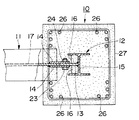
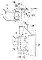
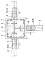
図1は、本発明に係る柱と梁の結合構造の第1の実施形態を示す断面図である。同図に示すように、この柱と梁の結合構造は、例えば鉄筋鉄骨コンクリート造の柱10と、例えばH型鋼で形成された鉄骨造の梁11とを結合するものであり、柱10の例えばH型鋼で形成された中心鉄骨12の側面に突出する1個の第1の結合用縦板13と、梁11の端面に突出する2個の第2の結合用縦板14、14とを備えている。
【0010】
第1の結合用縦板13は、図2にも示すように例えば中心鉄骨12のウェブ15の中央に立設されている。また、第1の結合用縦板13の根元側には、補強用のリブ16、16が取り付けられている。第2の結合用縦板14、14は、梁11のウェブ17を挟むようにして互いに平行に配置されている。この第2の結合用縦板14、14の間隔hは、第1の結合用縦板13の厚さtより少し大きくなっている。
【0011】
第1の結合用縦板13及び第2の結合用縦板14、14には、縦一列に同一のピッチで複数のボルト孔20、21が設けられている。更に、第1の結合用縦板13の下端には、適宜な大きさの受け板22(図1)が設けられている。
【0012】
柱10と梁11とを接合する場合は、図1に示すように中心鉄骨12の第1の結合用縦板13を梁11の第2の結合用縦板14、14で挟み、第2の結合用縦板14、14を第1の結合用縦板13の下端にある受け板22上に載置する。次に、第1の結合用縦板13と第2の結合用縦板14、14のボルト孔20、21にボルト23を通し、このボルト23にナット24を締結する。これによって、第1の結合用縦板13と第2の結合用縦板14、14とが固定されて、柱10の中心鉄骨12と梁11とが確実に結合される。
【0013】
次に、中心鉄骨12の周囲に鉄筋25を配置し、その外側に型枠(図示せず)を配置する。そして、型枠の内側にコンクリート27を打設する。これで、結合された第1及び第2の結合用縦板13、14は、打設したコンクリート27内に埋設される。このときには、梁11の端部も柱10のコンクリート27内に埋設される。
【0014】
上述のように、この柱と梁の結合構造においては、柱10の中心鉄骨12の側面に突出した第1の結合用縦板13と、梁11の端部に突出した第2の結合用縦板14、14とをボルト23及びナット24で締結することにより、柱10と梁11とを結合するようになっているので、第1及び第2の結合用縦板13、14の横幅を例えばボルト23を1個だけ取り付けるのに必要な寸法とし、縦の長さはボルト23を必要な数だけ取り付けることが可能な寸法にすることができる。
【0015】
これにより、第1及び第2の結合用縦板13、14の横幅を小さくすることができるので、第1及び第2の結合用縦板13、14を柱10のコンクリート27内に埋設することができる。したがって、従来のように柱と梁の間にボルト結合ゾーンを設ける必要が無くなるので後施工が不要になり、これにより施工性を向上させることができる。また、第1の結合用縦板13は中心鉄骨12の任意の位置に設けることができるので、梁11を柱10の任意の位置に結合することが可能になる。
【0016】
上述した第1の実施の形態においては、柱10に1個の梁11を結合した場合について説明したが、図3に示す第2の実施の形態のように、柱30の両側に例えばH型鋼で形成された2個の梁31を結合することもできる。
【0017】
この場合は、柱30の中心鉄骨32のウェブ35の両側に第1の結合用縦板33、33を立設すると共に、各梁31、31の端部にそれぞれ2個の第2の結合用縦板34、34を平行に取り付け、これらの第2の結合用縦板34、34で第1の結合用縦板33を挟んだ状態でボルト及びナットで固定する。なお、図中の符号36は鉄筋、37はコンクリート、38はウェブ、39はリブである。
【0018】
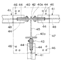
図4は、第3の実施の形態を示す。この場合は、柱40のH型鋼で形成された中心鉄骨42の例えば図中下側のフランジ40aの中央に、第1の結合用縦板43を立設する。この第1の結合用縦板43と、他方のフランジ40aの両側の板部分にボルト孔(図示せず)を設ける。また、各梁41の端部には、第1の実施の形態と同様にそれぞれ2個の第2の結合用縦板44、44を取り付ける。
【0019】
そして、1個の梁41は、その第2の結合用縦板44、44の間に、中心鉄骨42の一方のフランジ40aに立設した第1の結合用縦板43を挟んだ状態でボルト及びナットで固定する。また、残りの2個の梁41、41は、それぞれの第2の結合用縦板44、44の間に、他方のフランジ40aの板部分を挟んだ状態でボルト及びナットで固定する。これにより、柱40に3個の梁41を取り付けることができる。図中の符号46は鉄筋、47はコンクリート、45、48はウェブである。
【0020】
この第3の実施の形態によれば、中心鉄骨42のフランジ40aを第1の結合用縦板として利用しているので、第1の結合用縦板として他の部品を用意する必要が無く、これにより部品点数を低減してコストダウンを図ることができる。
【0021】
図5は第4の実施の形態を示す。この第4の実施の形態では、柱50に4個の梁51を結合するものであり、柱50の中心鉄骨52のウェブ55の両側に第1の結合用縦板53、53を立設すると共に、両側のフランジ50aの中央にも第1の結合用縦板53、53を立設する。
【0022】
また、4個の梁51の端部にはそれぞれ2個の第2の結合用縦板54、54を平行に取り付ける。そして、第1の実施の形態と同様に第1及び第2の結合用縦板53、54をボルト及びナットで固定する。図中の符号56は鉄筋、57はコンクリートである。
【0023】
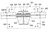
図6は第5の実施の形態を示す。この第5の実施の形態では、柱60のH型鋼で形成された中心鉄骨62のウェブ65の両側に、2個の第1の結合用縦板63、63を所定の間隔で平行に立設する。また、2個の梁61のそれぞれの端部には、そのウェブ68に突き当てて1個の第2の結合用縦板64を取り付ける。
【0024】
そして、中心鉄骨62の第1の結合用縦板63、63の間に第2の結合用縦板64を差し込んで、ボルト及びナットで固定する。これにより、柱60と梁61、61とを確実に結合することができる。なお、図中の符号66は鉄筋、67はコンクリートである。
【0025】
図7は第6の実施の形態を示す。この第6の実施の形態は、鉄骨鉄筋コンクリート造の柱70と、鉄骨コンクリート造の梁71とを結合するものであり、柱70の例えば丸鋼管で形成された中心鉄骨72の90ずつ離れた3箇所に、それぞれ2個の第1の結合用縦板73、73を適宜な間隔を開けて平行に立設する。
【0026】
また、梁71は、コンクリート80内のH型鋼で形成された中心鉄骨81の端部に、そのウェブ78に突き当てるようにして1個の第2の結合用縦板74を取り付ける。なお、ウェブ78の端部には補強用のプレート82を貼り付けることができる。
【0027】
そして、第2の結合用縦板74を第1の結合用縦板73、73の間に差し込んでボルト及びナットで固定することにより、柱70の中心鉄骨72と梁71の中心鉄骨81とを確実に結合することができる。この場合は、梁71を柱70の直近までプレキャスト化することができるので、施工が容易になる。
【0028】
なお、上述の実施の形態では第1及び第2の結合用縦板を、1個又は2個にした場合について説明したが、これらの第1及び第2の結合用縦板は、任意の数にすることができる。また、柱は鉄骨コンクリート造としても良い。
【0029】
【発明の効果】
以上説明したように、本発明の柱と梁の結合構造によれば、柱の第1の結合用縦板と、梁の第2の結合用縦板とを縦に長くすることにより、ボルトを必要な数だけ取り付けることができるので、第1及び第2の結合用縦板の横幅を小さくすることができ、これにより、第1及び第2の結合用縦板を柱のコンクリート内に埋設することができるので、従来のように後施工部分となるボルト接合ゾーンを設ける必要がないため、施工が容易になる。
【0030】
また、第1の結合用縦板は中心鉄骨の任意の位置に取り付けることができるので、梁を柱の任意の位置に設けることができる。
柱の中心鉄骨をH型鋼とし、このH型鋼のフランジ部分を第1の結合用縦板として用いた場合は、柱の中心鉄骨以外に特別な結合用部品を使用する必要が無いので、部品点数を低減してコストダウンを図ることができる。
【図面の簡単な説明】
【図1】本発明に係る柱と梁の結合構造の第1の実施形態を示す断面図である。
【図2】本発明に係る柱と梁の結合構造の第1の実施形態の中心鉄骨と梁とを示す分解斜視図である。
【図3】本発明に係る柱と梁の結合構造の第2の実施形態を示す断面図である。
【図4】本発明に係る柱と梁の結合構造の第3の実施形態を示す断面図である。
【図5】本発明に係る柱と梁の結合構造の第4の実施形態を示す断面図である。
【図6】本発明に係る柱と梁の結合構造の第5の実施形態を示す断面図である。
【図7】本発明に係る柱と梁の結合構造の第6の実施形態を示す断面図である。
【図8】従来例に係る柱と梁の結合構造を示す断面図である。
【符号の説明】
10、30、40、50、60、70 柱
11、31、41、51、61、71 梁
12、32、42、52、62、72 中心鉄骨
13、33、43、53、63、73 第1の結合用縦板
14、34、44、54、64、74 第2の結合用縦板
27、37、47、57、67、77 コンクリート
40a フランジ部分[0001]
BACKGROUND OF THE INVENTION
The present invention relates to a column / beam connection structure, and more specifically, in a steel-concrete structure, a reinforced steel-concrete structure, or a mixed structure, the mounting position of the beam can be arbitrarily set, and the workability can be improved. Related to the connection structure of pillars and beams.
[0002]
[Prior art]
Conventionally, when a column and a beam are coupled in a reinforced steel concrete structure, for example, a
[0003]
[Problems to be solved by the invention]
However, in the above-described conventional column-beam connection structure, when the
[0004]
Furthermore, since the horizontal width of the
An object of the present invention is to solve such a problem, and it is possible to improve the workability by preventing the occurrence of a post-installation part, and to make it possible to arbitrarily set the beam mounting position. It is to provide a bonding structure.
[0005]
[Means for Solving the Problems]
The present invention is a coupled structure of columns and beams, and is configured as follows in order to solve the above technical problem. That is, the present invention is a combined structure of a steel-concrete or reinforced steel-concrete column and a steel-frame, steel-concrete or reinforced steel-concrete beam.
At least one first coupling vertical plate protruding from a side surface of the central steel frame of the column;
Projecting from the end surface of the center steel of the beam, and comprises at least one second coupling vertical plate protrudes in the vertical direction from the upper and lower surfaces of the beam,
The first coupling vertical plate and the second coupling vertical plate are coupled by a plurality of bolts,
The first coupling vertical plate and the second coupling vertical plate are embedded in the concrete of the pillar.
[0006]
Here, two of the second coupling vertical plates are provided with a gap,
A receiving plate is provided below the first coupling vertical plate;
The first coupling vertical plate may be sandwiched between the two second coupling vertical plates and placed on the receiving plate.
[0007]
The column may be H-shaped steel, and the flange portion of the H-shaped steel may be used as the first coupling vertical plate. In this case, it is not necessary to use a special connecting part other than the central steel frame.
[0008]
DETAILED DESCRIPTION OF THE INVENTION
DESCRIPTION OF THE PREFERRED EMBODIMENTS Embodiments of a column / beam connection structure according to the present invention will be described below in detail with reference to the drawings.
[0009]
FIG. 1 is a cross-sectional view showing a first embodiment of a coupled structure of columns and beams according to the present invention. As shown in the figure, this pillar-to-beam connection structure is a structure in which, for example, a reinforced
[0010]
As shown in FIG. 2, the first coupling
[0011]
The first coupling
[0012]
When the
[0013]
Next, a reinforcing bar 25 is arranged around the
[0014]
As described above, in this column-beam coupling structure, the first coupling
[0015]
Thereby, since the horizontal width of the first and second coupling
[0016]
In the first embodiment described above, the case where one beam 11 is coupled to the
[0017]
In this case, the first coupling
[0018]
FIG. 4 shows a third embodiment. In this case, the first coupling
[0019]
One
[0020]
According to the third embodiment, since the
[0021]
FIG. 5 shows a fourth embodiment. In the fourth embodiment, four
[0022]
In addition, two second coupling
[0023]
FIG. 6 shows a fifth embodiment. In the fifth embodiment, two first connecting
[0024]
Then, the second coupling
[0025]
FIG. 7 shows a sixth embodiment. In the sixth embodiment, a steel-reinforced
[0026]
In addition, the
[0027]
Then, by inserting the second coupling
[0028]
In the above-described embodiment, the case where the number of first and second coupling vertical plates is one or two has been described. However, the number of these first and second coupling vertical plates may be any number. Can be. Also, the pillar may be a steel concrete structure.
[0029]
【The invention's effect】
As described above, according to the column-to-beam coupling structure of the present invention, the first coupling vertical plate of the column and the second coupling vertical plate of the beam are lengthened in the vertical direction. Since the required number can be attached, the horizontal width of the first and second coupling vertical plates can be reduced, whereby the first and second coupling vertical plates are embedded in the concrete of the column. Therefore, since it is not necessary to provide a bolt joint zone as a post-installation part as in the prior art, construction is facilitated.
[0030]
Moreover, since the 1st connection vertical board can be attached to the arbitrary positions of a center steel frame, a beam can be provided in the arbitrary positions of a pillar.
If the central steel frame of the column is H-shaped steel and the flange part of this H-shaped steel is used as the first vertical plate for coupling, there is no need to use any special coupling parts other than the central steel frame of the column. Can be reduced to reduce costs.
[Brief description of the drawings]
FIG. 1 is a cross-sectional view showing a first embodiment of a coupled structure of columns and beams according to the present invention.
FIG. 2 is an exploded perspective view showing a central steel frame and a beam of a first embodiment of a column / beam coupling structure according to the present invention.
FIG. 3 is a cross-sectional view showing a second embodiment of a column-beam connection structure according to the present invention.
FIG. 4 is a cross-sectional view showing a third embodiment of a coupled structure of columns and beams according to the present invention.
FIG. 5 is a cross-sectional view showing a fourth embodiment of a column-beam coupling structure according to the present invention.
FIG. 6 is a cross-sectional view showing a fifth embodiment of a column / beam coupling structure according to the present invention;
FIG. 7 is a cross-sectional view showing a sixth embodiment of a column / beam coupling structure according to the present invention;
FIG. 8 is a cross-sectional view showing a column-beam connection structure according to a conventional example.
[Explanation of symbols]
10, 30, 40, 50, 60, 70
Claims (2)
前記柱の中心鉄骨の側面から突出する少なくとも1個の第1の結合用縦板と、
前記梁の端面から突出し、且つ前記梁の上下面より上下方向に突出する少なくとも1個の第2の結合用縦板とを備え、
前記第1の結合用縦板と前記第2の結合用縦板とがボルトで結合され、
前記第1の結合用縦板及び前記第2の結合用縦板が、前記柱のコンクリートに埋設されることを特徴とする柱と梁の結合構造。In the connecting structure of steel concrete or reinforced steel concrete columns and steel, steel concrete or reinforced steel concrete beams,
At least one first coupling vertical plate protruding from a side surface of the central steel frame of the column;
And at least one second coupling vertical plate protruding from the end surface of the beam and protruding vertically from the upper and lower surfaces of the beam ,
The first coupling vertical plate and the second coupling vertical plate are coupled by a bolt,
The column-to-beam coupling structure, wherein the first coupling vertical plate and the second coupling vertical plate are embedded in the concrete of the column.
前記第1の結合用縦板の下側に受け板が設けられ、
前記第1の結合用縦板が前記2個の第2の結合用縦板によって挟まれ、且つ前記受け板上に載置されていることを特徴とする請求項1に記載の柱と梁の結合構造。 Two of the second coupling vertical plates are provided with a gap,
A receiving plate is provided below the first coupling vertical plate;
The column and beam according to claim 1, wherein the first coupling vertical plate is sandwiched between the two second coupling vertical plates and placed on the receiving plate . Bond structure.
Priority Applications (1)
| Application Number | Priority Date | Filing Date | Title |
|---|---|---|---|
| JP23622397A JP3828641B2 (en) | 1997-09-01 | 1997-09-01 | Column and beam connection structure |
Applications Claiming Priority (1)
| Application Number | Priority Date | Filing Date | Title |
|---|---|---|---|
| JP23622397A JP3828641B2 (en) | 1997-09-01 | 1997-09-01 | Column and beam connection structure |
Publications (2)
| Publication Number | Publication Date |
|---|---|
| JPH1181454A JPH1181454A (en) | 1999-03-26 |
| JP3828641B2 true JP3828641B2 (en) | 2006-10-04 |
Family
ID=16997618
Family Applications (1)
| Application Number | Title | Priority Date | Filing Date |
|---|---|---|---|
| JP23622397A Expired - Fee Related JP3828641B2 (en) | 1997-09-01 | 1997-09-01 | Column and beam connection structure |
Country Status (1)
| Country | Link |
|---|---|
| JP (1) | JP3828641B2 (en) |
Families Citing this family (3)
| Publication number | Priority date | Publication date | Assignee | Title |
|---|---|---|---|---|
| KR100346960B1 (en) * | 1999-04-20 | 2002-07-31 | (주)씨.에스 구조 엔지니어링 | An apparatus and method for anchoring steel column to concrete |
| CN107965055B (en) * | 2017-12-15 | 2023-10-03 | 北京万兴建筑集团有限公司 | Connecting node of H-shaped steel beam and steel reinforced concrete beam and manufacturing method |
| CN115233837B (en) * | 2022-08-19 | 2023-06-30 | 重庆三峡学院 | Connecting node for assembled concrete frame and steel energy dissipation piece |
-
1997
- 1997-09-01 JP JP23622397A patent/JP3828641B2/en not_active Expired - Fee Related
Also Published As
| Publication number | Publication date |
|---|---|
| JPH1181454A (en) | 1999-03-26 |
Similar Documents
| Publication | Publication Date | Title |
|---|---|---|
| JP2645365B2 (en) | Beam-column joint | |
| JP2928832B2 (en) | Pillar configuration method | |
| KR102200236B1 (en) | Wall module and wall structure | |
| JP3828641B2 (en) | Column and beam connection structure | |
| JP4328455B2 (en) | Unit building | |
| JPH01223247A (en) | Joint structure between steel-concrete composed board and steel girder | |
| JP2001164658A (en) | Beam joining structure and unit building | |
| JP7032051B2 (en) | Floor structure construction method and floor structure reuse method | |
| JP2618205B2 (en) | Horizontal connection structure and horizontal connection material of main girder in temporary bridge | |
| JP3462374B2 (en) | Beam formwork structure | |
| JP4656460B2 (en) | Building reinforcement structure | |
| JP3833514B2 (en) | Formwork structure | |
| JP3055431U (en) | Composite pillars for steel structures | |
| JPH06185122A (en) | Building unit, and unit building using the same | |
| JP4449891B2 (en) | Unit building | |
| JP3639368B2 (en) | Foundation structure of steel column base | |
| JP2000234390A (en) | Reinforcing structure of unit building and building unit | |
| JPH11323839A (en) | Girder connecting method for suspended structure | |
| JP2600411Y2 (en) | Column-beam joint structure | |
| JP3749935B2 (en) | Column and beam construction method and enclosure | |
| JP2895815B2 (en) | Floor panel mounting structure | |
| JPH04128455A (en) | Floor device | |
| JP4136200B2 (en) | Connection structure between reinforced concrete columns and steel beams | |
| JPH09317000A (en) | Connection method and structure of column and beam | |
| JPH11336190A (en) | Construction method for steel frame column and steel frame girder |
Legal Events
| Date | Code | Title | Description |
|---|---|---|---|
| A621 | Written request for application examination |
Free format text: JAPANESE INTERMEDIATE CODE: A621 Effective date: 20040607 |
|
| A977 | Report on retrieval |
Free format text: JAPANESE INTERMEDIATE CODE: A971007 Effective date: 20060202 |
|
| A131 | Notification of reasons for refusal |
Free format text: JAPANESE INTERMEDIATE CODE: A131 Effective date: 20060221 |
|
| A521 | Written amendment |
Free format text: JAPANESE INTERMEDIATE CODE: A523 Effective date: 20060424 |
|
| TRDD | Decision of grant or rejection written | ||
| A01 | Written decision to grant a patent or to grant a registration (utility model) |
Free format text: JAPANESE INTERMEDIATE CODE: A01 Effective date: 20060627 |
|
| A61 | First payment of annual fees (during grant procedure) |
Free format text: JAPANESE INTERMEDIATE CODE: A61 Effective date: 20060707 |
|
| R150 | Certificate of patent or registration of utility model |
Free format text: JAPANESE INTERMEDIATE CODE: R150 |
|
| FPAY | Renewal fee payment (event date is renewal date of database) |
Free format text: PAYMENT UNTIL: 20100714 Year of fee payment: 4 |
|
| FPAY | Renewal fee payment (event date is renewal date of database) |
Free format text: PAYMENT UNTIL: 20110714 Year of fee payment: 5 |
|
| FPAY | Renewal fee payment (event date is renewal date of database) |
Free format text: PAYMENT UNTIL: 20120714 Year of fee payment: 6 |
|
| FPAY | Renewal fee payment (event date is renewal date of database) |
Free format text: PAYMENT UNTIL: 20120714 Year of fee payment: 6 |
|
| FPAY | Renewal fee payment (event date is renewal date of database) |
Free format text: PAYMENT UNTIL: 20130714 Year of fee payment: 7 |
|
| LAPS | Cancellation because of no payment of annual fees |