JP3878632B2 - Reinforced beams and unit buildings - Google Patents
Reinforced beams and unit buildings Download PDFInfo
- Publication number
- JP3878632B2 JP3878632B2 JP2004233651A JP2004233651A JP3878632B2 JP 3878632 B2 JP3878632 B2 JP 3878632B2 JP 2004233651 A JP2004233651 A JP 2004233651A JP 2004233651 A JP2004233651 A JP 2004233651A JP 3878632 B2 JP3878632 B2 JP 3878632B2
- Authority
- JP
- Japan
- Prior art keywords
- large space
- reinforcing beam
- building
- unit
- reinforcing
- Prior art date
- Legal status (The legal status is an assumption and is not a legal conclusion. Google has not performed a legal analysis and makes no representation as to the accuracy of the status listed.)
- Expired - Fee Related
Links
Images


Description
本発明は、建物ユニットの柱の一部を省略したユニット(以下、大空間用建物ユニットと呼ぶ)を用いて広い空間を造り出すにあたって、大空間用建物ユニットの柱の一部が省略された部分に用いられる補強梁及びこの補強梁を用いたユニット式建物に関する。 In the present invention, when a wide space is created using a unit in which a part of a pillar of a building unit is omitted (hereinafter referred to as a large space building unit), a part of the pillar of the large space building unit is omitted. The present invention relates to a reinforced beam used for the building and a unit type building using the reinforced beam.
従来から、工場で製造した箱状の建物ユニットを、建築現場で複数組合わせて建築されるユニット式建物が利用されている。ユニット式建物を形成する建物ユニットとしては、四隅の柱の上下端を天井梁および床梁で連結した直方体状の骨組みを有するものが一般的である。 Conventionally, a unit type building constructed by combining a plurality of box-shaped building units manufactured at a factory at a construction site has been used. As a building unit forming a unit type building, one having a rectangular parallelepiped frame in which upper and lower ends of pillars at four corners are connected by a ceiling beam and a floor beam is generally used.
このような建物ユニットを複数組み合わせて一つの居室を造る場合、その中央部は複数の柱が組み合わされる状態となり広い空間を形成できない。このため、建物ユニットの柱の一部を省略した上記の大空間用建物ユニットを用いて広い空間を造り出すという方法が採られている。
しかし、このような大空間用建物ユニットを用いると、建物ユニットの剛性が低下し、上方に載置される建物ユニット等の荷重を支持しきれなくなる可能性がある。
When one living room is constructed by combining a plurality of such building units, the central portion is in a state in which a plurality of pillars are combined, and a wide space cannot be formed. For this reason, a method of creating a wide space using the large space building unit in which a part of the pillar of the building unit is omitted is employed.
However, when such a large space building unit is used, there is a possibility that the rigidity of the building unit is lowered and the load of the building unit or the like placed above cannot be supported.
これを解決するため、柱の一部が省略された部分を中央にして、その両側に配置される柱の上端を連結する2スパン分の補強梁が設けられることがある(例えば、特許文献1参照)。 In order to solve this, there are cases where reinforcing beams for two spans are provided to connect the upper ends of the pillars arranged on both sides of the part where the part of the pillars is omitted (for example, Patent Document 1). reference).
ところで、ユニット式建物を施工する際には、隣接する各建物ユニットを位置決めする必要がある。通常の建物ユニットにおいては、突き合わされた各コーナー部に各々設けられた位置決め用のピンに、それに対応した孔が形成された一枚の金属板を上から差し込むことにより行われている。したがって、突き合わされた各コーナー部間の隙間は金属板で覆われることになる。 By the way, when constructing a unit type building, it is necessary to position each adjacent building unit. In a normal building unit, a single metal plate in which a hole corresponding to the positioning pin provided at each corner portion that is abutted is inserted from above. Therefore, the gaps between the corner portions that are abutted are covered with the metal plate.
しかし、前述の大空間用建物ユニットを用いた施工においては、補強梁が複数の大空間用建物ユニットに跨って取り付けられるため、前述の位置決め技術をそのまま使用できないという問題がある。 However, in the construction using the above-described large space building unit, there is a problem that the above-described positioning technique cannot be used as it is because the reinforcing beam is attached across a plurality of large space building units.
本発明はこのような事情に鑑みてなされたものであり、ユニット式建物において、隣接する大空間用建物ユニットの位置決めが容易となるように構成した大空間用建物ユニットに用いる補強梁を提供することを第1の目的としている。
また、本発明は、このような補強梁を用いたユニット式建物を提供することを第2の目的としている。
This invention is made | formed in view of such a situation, and provides the reinforcement beam used for the building unit for large spaces comprised so that the positioning of the building unit for large spaces which adjoins may become easy in a unit type building. This is the first purpose.
Moreover, this invention makes it the 2nd objective to provide the unit type building using such a reinforcement beam.
このような目的に応えるために本発明は、位置決めに用いる部材を補強梁本体に取り付けることで、前記第1の目的を達成しようとするものである。 In order to meet such an object, the present invention aims to achieve the first object by attaching a member used for positioning to a reinforcing beam body.
添付図面を参照して具体的に説明すると、請求項1に記載の発明は、四隅の柱31の上下端を天井梁32及び床梁33で連結した直方体状の骨組み30を有する通常の建物ユニット121C(122C)と、この通常の建物ユニット121C(122C)の骨組み30から一本の柱31を省略した複数の大空間用建物ユニット121A(122A)、121B(122B)とを含んで形成されたユニット式建物10の内部に、柱31のない大空間を形成するために複数の大空間用建物ユニット121A(122A)、121B(122B)の柱31を省略した部位を隣接配置した際に、前記隣接した大空間用建物ユニット121A(122A)、121B(122B)間を連結補強するための補強梁40であって、隣接した大空間用建物ユニットに跨り大空間用建物ユニットの梁に沿って設けられる長尺状の補強梁本体41と、この補強梁本体側面の上下方向のほぼ中央位置に水平方向に突出して取り付けられ、隣接する大空間用建物ユニット同士の位置決めを行うシア−プレート42とを備え、このシアープレート42は、大空間用建物ユニットの柱を省略した部位の上面に臨んで、この柱を省略した部位を位置決めピンを介して位置決めするように構成されていることを特徴とする補強梁40である。
Referring to the attached drawings, the invention according to
このような請求項1記載の発明によれば、位置決めに用いるシア−プレート43が補強梁本体41に取り付けられているから、大空間用建物ユニット121A(122A)、121B(122B)の柱省略接合部20の補強と隣接する各大空間用建物ユニット121A、121B間の位置決めとを同時に行うことができる。したがって、補強梁40を用いるユニット式建物10の施工作業が簡易になる。
According to the invention described in
請求項2記載の発明は、請求項1記載の補強梁40において、前記シア−プレート42の断面はL字形状に形成されており、その一辺が前記大空間用建物ユニット121A、121Bに接合され、その他辺が前記補強梁本体41に接合されていることを特徴とする補強梁40である。
According to a second aspect of the present invention, in the
この請求項2記載の発明によれば、シア−プレート42の断面がL字形状に形成されているため取り付けが容易になる。また、補強梁本体41とシア−プレート42との接合面積がL字の一辺により確保できるから、それらの接合強度を大きくできる。
According to the second aspect of the present invention, since the cross section of the
請求項3記載の発明は、請求項1または請求項2記載の補強梁40を用いることを特徴とするユニット式建物10である。
この請求項3記載の発明によれば、請求項1または請求項2記載された補強梁40の効果を達成できるユニット式建物10が得られる。すなわち、その施工の際に位置決めが作業が容易にでき、かつ、簡易な構造の補強梁40で剛性の高いユニット式建物10を得ることができる。
The invention according to claim 3 is a
According to the invention described in claim 3, the
以上説明したように本発明に係る補強梁及びユニット式建物によれば、以下のような種々優れた効果を奏する。
すなわち、請求項1記載の発明によれば、位置決めに用いるシア−プレートが補強梁本体に取り付けられているから、大空間用建物ユニットの柱省略接合部の補強と隣接する各大空間用建物ユニット間の位置決めとを同時に行うことができる。したがって、補強梁を用いるユニット式建物の施工作業が簡易になる。
As described above, according to the reinforcing beam and the unit type building according to the present invention, the following excellent effects are obtained.
That is, according to the first aspect of the present invention, since the shear plate used for positioning is attached to the reinforcing beam body, each large space building unit adjacent to the reinforcement of the column omission joint portion of the large space building unit. Positioning between the two can be performed simultaneously. Therefore, the construction work of the unit type building using the reinforcing beam is simplified.
請求項2記載の発明によれば、シア−プレートの断面がL字形状に形成されているため取り付けが容易になる。また、補強梁本体とシア−プレートとの接合面積がL字の一辺により確保できるから、それらの接合強度を大きくできる。 According to invention of Claim 2, since the cross section of the shear plate is formed in L shape, attachment becomes easy. Further, since the joining area between the reinforcing beam main body and the shear plate can be secured by one side of the L shape, the joining strength can be increased.
請求項3記載の発明によれば、請求項1または請求項2記載された補強梁の効果を達成できるユニット式建物が得られる。すなわち、その施工の際に位置決めが作業が容易にでき、かつ、簡易な構造の補強梁で剛性の高いユニット式建物を得ることができる。
According to invention of Claim 3, the unit type building which can achieve the effect of the reinforcement beam described in
図1ないし図9は本発明に係る大空間用建物ユニットに用いる補強梁及びこれを用いたユニット式建物の一実施の形態を示すものである。
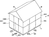
これらの図において、図1には、本発明の一実施形態に係るユニット式建物10が示されている。ユニット式建物10は、基礎11の上に載置される建物本体12及び屋根13を備えたものである。建物本体12は、箱状に形成された複数の建物ユニット120を組合わせて造られたものである。
1 to 9 show an embodiment of a reinforcing beam used in a large space building unit and a unit building using the same.
In these drawings, FIG. 1 shows a
ユニット式建物10の一階部分は、図2に示されるように、建物本体12の外周縁に沿って四隅の柱31を全て有する通常の建物ユニット121CがL字形状に5個並べて配置され、このL字の入隅部分に柱31の一本が省略された大空間用建物ユニット121A、121Bが各々二つずつ配置されることによって形成されている。ユニット式建物10の二階部分も下階と同様に、L字形状に配置された通常の建物ユニット122C及び大空間用建物ユニット122A、122Bにより形成されている(図1参照)。
As shown in FIG. 2, the first floor portion of the
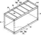
大空間用建物ユニット121A(122A)は、図3に示されるように、角柱状に形成された三本の金属製の柱31の上下端が金属製の天井梁32および床梁33で連結されている。また、柱31が省略された一辺には、取り外し可能な仮柱37が設けられ直方体状の骨組み30を構成している。
ここにおいて、天井梁32は、断面C型に形成された金属製の短辺天井梁32A及び同様の長辺天井梁32Bの二種類からなる。一方、床梁33も断面C型に形成された金属製の短辺床梁33Aおよび同様の長辺床梁33Bの二種類からなる。対向する長辺天井梁32Bの間には、木製柱状の天井小梁34が複数条架け渡され、この天井小梁34に木製板状の天井面材36が固定されている。また、対向する長辺床梁33Bの間には、図示しない根太が複数条架け渡され、この上に床を形成する木製板状の床面材35が貼られている。
In the large
Here, the
また、もう一方の大空間用建物ユニット121B(122B)は、大空間用建物ユニット121Aの仮柱37が柱31とされ、その隣に位置する二本の柱31のうちの一本が省略されたものである他は同一構成である。すなわち、両者は、いわゆる勝手違いな形状とされている。
なお、一階を形成する通常の建物ユニット121C及び二階を形成する通常の建物ユニット122Cについては、四隅の柱31を全て備えた点のみが図3に示す大空間用建物ユニット121Aと異なり、その他の構成は同一である。
Further, in the other large
Note that the
図2において、一点鎖線のハッチングで示される各々2個ずつの大空間用建物ユニット121A及び121Bは、各々の柱省略コーナー部同士が寄せ合わされて柱省略接合部20を形成する状態で隣接配置されている。これにより、大空間用建物ユニット121A、121Bにより形成される居室の中心部分には、柱31等の障害物が何ら存在しない広い空間が形成される。
In FIG. 2, each of the two large
このような大空間用建物ユニット121A、121Bにおいて、その寄せ合わされた短辺天井梁32Aの間には、図4に示されるように、板状に形成された長尺状の金属製補強梁40が短辺天井梁32Aに沿うように設置され、これにより隣接する大空間用建物ユニット121A、121Bが連結補強されている。
In such large
図5ないし図9を用いて、補強梁40の構成をより詳細に説明する。
すなわち、補強梁40は、柱省略接合部20の補強に寄与する長尺、板状の補強梁本体41を備え、この補強梁本体41の両側面には、補強梁本体41の長手方向に直交するように平面矩形に形成された金属製板状のスチフナ43が取り付けられている。
The configuration of the reinforcing
That is, the reinforcing
柱省略接合部20において、スチフナ43の両側面に、大空間用建物ユニット121A、121Bの位置決めに用いる金属製シア−プレート42が、補強梁本体41の長手方向に沿って、補強梁本体41の上下方向のほぼ中央位置に取り付けられている。ここにおいて、シア−プレート42は、矩形金属板の二辺が折り曲げられたものであり、直交する二つの断面がそれぞれL字形状に形成されている。
In the column omitted joint 20,
そして、このシアープレート42は、大空間用建物ユニット121A,121Bの柱省略接合部20の上面に臨み、該柱省略接合部20の上面との間での位置決めが行えるように上方から対向するとともに、その一辺が補強梁本体41に当接して溶接等により固定されている。さらに、ここでは、このシアープレート42の他辺が、上記の一辺と同様にしてスチフナ43に固定されている。これにより柱省略接合部20において、補強梁本体41、シア−プレート42、スチフナ43の三部材が各々直交、かつ、一体として形成される。
The
一方、補強梁本体41の両端部に位置するシア−プレート42は、矩形金属板の一辺のみが断面L字形状に折り曲げられて形成され、この一辺が補強梁本体41に当接して溶接等により固定されている。これら各位置のシア−プレート42は、各大空間用建物ユニット121A、121Bにおいて、突き合わされる各短辺天井梁32Aの両端部分に対応する位置に全部で8個設けられている。
On the other hand, the
また、上階の大空間用建物ユニット122A、122Bの短辺床梁33Aの上部には複数個の金属製ナット52が補強梁本体41の長手方向に沿って一列に並ぶように設けられている。このナット52に変形防止手段である金属製の変形防止ボルト51が螺合され、これらのナット52及び変形防止ボルト51により補強梁変形防止構造50が構成される(図5、図9参照)。この変形防止ボルト51の先端部は、補強梁本体41にその両側から互いに対向して当接される(図9参照)。
Further, a plurality of
このように構成された補強梁40と、上階の大空間用建物ユニット122A、122Bの短辺床梁33Aと、下階の大空間用建物ユニット121A、121Bの短辺天井梁32Aとの接合手順を説明する。
工場で大空間用建物ユニット121A(122A)、121B(122B)、を複数製造した後、建築現場に搬送する。この際、搬送時における大空間用建物ユニット121A(122A)、121B(122B)の変形を防止するために、柱31が省略されたコーナー部には仮柱37が設けられる。
Joining of the reinforcing
After a plurality of large
一階部分を構成する大空間用建物ユニット121A、121Bを隣接配置し、短辺天井梁32Aに補強梁40を載置する(図4、図6参照)。この際、短辺天井梁32Aの柱省略コーナー部に設けられている位置決めピン53を、柱省略接合部20における各シア−プレート42に形成された孔421に差し込む。これにより、大空間用建物ユニット121A、121Bの位置決めが同時に行われることになる(図5、図6参照)。この状態では、補強梁本体41の略下半分が短辺天井梁32Aの間に挟まれ、スチフナ43の略下半分が長辺天井梁32Bの間に挟まれることになる(図6参照)。
The large
その後、二階を構成する大空間用建物ユニット122A、122Bを下階の大空間用建物ユニット121A、121Bの上に載置する。この際、前述の孔421を挿通し、突出した位置決めピン53の先端部が、上階の短辺床梁33Aの柱省略コーナー部下面に設けられた孔(図示省略)に挿入される。さらに、シア−プレート42に設けられた孔422を通じて上下の各大空間用建物ユニット122A(122B)と121A(121B)とを締結ボルト54及び締結ナット55で固定する(図5参照)。その後、短辺床梁33Aに設けられた複数のナット52に変形防止ボルト51を螺合し、この変形防止ボルト51の先端を補強梁本体41の両側から補強梁本体41に当接させる。
Thereafter, the large
これにより、補強梁40と、上階大空間用建物ユニット122A、122Bの短辺床梁33Aと、下階大空間用建物ユニット121A、121Bの短辺天井梁32Aとの接合が完了する。
ここで、仮柱37を取り外し、居室内に柱31等の障害物が何ら存在しない大空間が形成される。
This completes the joining of the reinforcing
Here, the temporary pillar 37 is removed, and a large space in which no obstacle such as the
上述のような本実施形態によれば、次のような効果がある。
(1)位置決めに用いるシア−プレート42が補強梁本体41に予め取り付けられているから、大空間用建物ユニット121A、121Bにおける柱省略接合部20の補強と、隣接する大空間用建物ユニット121A、121Bとの位置決めを同時に行うことができる。
(2)補強梁本体41に直交配置されたスチフナ43により、補強梁40の強度を向上させることができる。したがって、補強梁本体41をより薄して軽量化を図ることができるとともに、材料コストの削減が可能となる。
According to this embodiment as described above, the following effects are obtained.
(1) Since the
(2) The strength of the reinforcing
(3)スチフナ43をシア−プレート42で挟み込むことにより、スチフナ43の接合強度が向上できる。また、補強梁本体41、スチフナ43、シア−プレート42の三部材が互いに直交して接合されて一体となることから、補強梁40全体の強度が向上できる。
(4)シア−プレート42の断面がL字形状に形成されているため、その取り付けが容易になる。また、補強梁本体41とシア−プレート42との接合面積がある程度確保できるから、それらの接合強度を大きくできる。
(5)柱省略接合部20におけるシア−プレート42は、二辺が折り曲げられているから、補強梁本体41との接合強度を向上できるだけでなく、スチフナ43との接合強度も向上させることができる。したがって、補強梁40全体の強度がより大きくできる。また、大空間用建物ユニット121A、121Bの位置決めがより確実にできる。
(3) By sandwiching the
(4) Since the
(5) Since the two sides of the
(6)ナット52及び変形防止ボルト51からなる補強梁変形防止構造50を用いているから、補強梁本体41が薄い板状のものでも、そのわん曲が確実に防止できる。
(7)変形防止手段は、変形防止ボルト51を用いた非常に簡単なものであり、その製造コストが安価にできる。
(8)変形防止ボルト51は、補強梁本体41を挟んで対向配置されていることから、両側から補強梁本体41を確実に押さえ、そのわん曲を防止できる。
(6) Since the reinforcing beam
(7) The deformation preventing means is very simple using the
(8) Since the
(9)変形防止ボルト51は、補強梁本体41の長手方向に沿って複数配置されていることから、補強梁40が長くても、そのわん曲を確実に防止できる。したがって、より広い空間を有する居室を形成できる。
(10)変形防止ボルト51は、短辺床梁33Aに固定されたナット52に螺合されるものであるから、その取り付けが容易である。また、補強梁本体41に変形防止手段を設けるものではないから、補強梁本体41の基本構造に従来のものを採用できる。したがって、その開発コストが削減できる。
(11)シア−プレート42が補強梁本体41に設けられているから、ユニット式建物10の施工の際に隣接する大空間用建物ユニット121A、121B等の位置決め作業が容易にできる。また、補強梁本体41、シア−プレート42、スチフナ43の三部材が一体となり補強梁40の強度を向上させていること、かつ、補強梁変形防止構造50を用いていることから、より軽量化された補強梁40を用いて剛性の高いユニット式建物10を得ることができる。
(9) Since a plurality of the
(10) Since the
(11) Since the
なお、本発明は前記実施形態に限定されるものではなく、本発明の目的を達成できる範囲での変形、改良は、本発明に含まれるものである。 It should be noted that the present invention is not limited to the above-described embodiment, and modifications and improvements within the scope that can achieve the object of the present invention are included in the present invention.
前記実施形態において、補強梁40は、大空間用建物ユニット121A、121Bの短辺天井梁32Aを補強していたが、これに限らず、長辺天井梁32Bを補強するものでもよい。ただし、補強梁40を短辺天井梁32Aを補強するものとすることで、長辺天井梁32Bを補強する場合より高い剛性が確保できるので望ましい。
また、補強梁本体41は板状に形成されていたが、これに限らず、柱状あるいは扁平ブロック状等、他の形状でもよい。ただし、板状にすることで補強梁本体41を軽量化することができ望ましい。一方、柱状等にすることで各大空間用建物ユニット121A、121Bの間が広くなり、その分だけ広い空間を持つ居室を形成できる。
In the embodiment, the reinforcing
Further, the reinforcing
また、図10から図12の第1変形例ないし第3変形例に示すように、補強梁本体41に補強部材45、46、47を接合したものを用いてもよい。このようにすることで、補強梁40の断面係数が向上し、補強梁40の強度が向上して好ましい。なお、補強部材45、46、47は、補強梁本体41の長手方向に沿って、補強梁本体41と同じ長さ分だけ取り付けてもよいが、小片に分けて、適宜な位置に任意の数だけ取り付けてもよい。
Further, as shown in the first to third modifications of FIGS. 10 to 12, a reinforcing beam
前記実施形態において、シア−プレート42は、矩形金属板の少なくとも一辺が折り曲げられていたが、折り曲げない矩形板状のものをそのまま用いてもよい。ただし、折り曲げることで、補強梁本体41及びスチフナ43との接合面が大きくでき、各部材の接合強度を大きくできるので好ましい。また、その形状も矩形である必要はなく、例えば台形等でもよく、位置決めできる形状であればよい。
In the above-described embodiment, the
シア−プレート42は、各々二個ずつ合計四個の大空間用建物ユニット121A、121Bの位置決めを行うため、補強梁本体41の両側に設けられていたが、これに限らず、各々一個ずつの大空間用建物ユニット121A、121Bの位置決めに用いてもよく、この場合には、補強梁本体41の片面のみにシア−プレート42が設けられることになる。
The
前記実施形態において、スチフナ43は平面矩形状に形成されていたが、これに限ることなく、例えば台形、三角形等の他の形状でもよい。また、補強梁40の構成部材は、全て金属製のものを用いていたが、他の材質でも補強効果を奏するものであればよい。
In the above embodiment, the
前記実施形態において、補強梁変形防止構造50は、ナット52と変形防止ボルト51とを用いたものであるが、これに限らず、補強梁本体41のわん曲を防止できる構造であればよい。補強梁変形防止構造50は補強梁本体41の長手方向に沿って一列に設けられているが、これに限らず、二列以上でもよい。
また、前記実施形態および各変形例において、補強梁変形防止構造50は補強梁本体41の両側に設けられているが、これに限らず、片側でもよい。ただし、両側に設けることで補強梁本体41の変形を確実に防止できるので好ましい。
In the embodiment described above, the reinforcing beam
Moreover, in the said embodiment and each modification, although the reinforcement beam deformation |
10…ユニット式建物、121C、122C…通常の建物ユニット、121A、121B、122A、122B…大空間用建物ユニット、20…柱省略接合部、30…骨組み、31…柱、32…天井梁、33…床梁、40…補強梁、41…補強梁本体、42…シア−プレート、43…スチフナ、50…補強梁変形防止構造、51…変形防止ボルト、52…ナット。
DESCRIPTION OF
Claims (3)
この通常の建物ユニットの骨組みから一本の柱を省略した複数の大空間用建物ユニットとを含んで形成されたユニット式建物の内部に、柱のない大空間を形成するために複数の大空間用建物ユニットの柱を省略した部位を隣接配置した際に、前記隣接した大空間用建物ユニット間を連結補強するための補強梁であって、
隣接した大空間用建物ユニットに跨り大空間用建物ユニットの梁に沿って設けられる長尺状の補強梁本体と、
この補強梁本体側面の上下方向のほぼ中央位置に水平方向に突出して取り付けられ、隣接する大空間用建物ユニット同士の位置決めを行うシア−プレートとを備え、
このシアープレートは、大空間用建物ユニットの柱を省略した部位の上面に臨んで、この柱を省略した部位を位置決めピンを介して位置決めするように構成されていることを特徴とする補強梁。 A normal building unit having a rectangular frame structure in which upper and lower ends of pillars at four corners are connected by ceiling beams and floor beams;
In order to form a large space without pillars inside a unit type building formed by including a plurality of large space building units in which one pillar is omitted from the framework of this normal building unit A reinforcing beam for reinforcing the connection between the adjacent large space building units when a portion where the pillar of the building unit is omitted is adjacently arranged,
A long reinforcing beam body provided along the beam of the large space building unit straddling the adjacent large space building unit;
A projecting and mounting in the horizontal direction at a substantially central position in the vertical direction of the side of the reinforcing beam body, and a shear plate for positioning adjacent large space building units,
The shear plate is configured to face the upper surface of a portion of the building unit for large space from which a column is omitted, and to position the portion from which the column is omitted through a positioning pin.
前記シア−プレートは断面L字形状に形成されており、
その一辺が前記大空間用建物ユニットに接合され、その他辺が前記補強梁本体に接合されていることを特徴とする補強梁。 The reinforcing beam according to claim 1 ,
The shear plate has an L-shaped cross section,
One side is joined to the large space building unit, and the other side is joined to the reinforcing beam body.
Priority Applications (1)
| Application Number | Priority Date | Filing Date | Title |
|---|---|---|---|
| JP2004233651A JP3878632B2 (en) | 2004-08-10 | 2004-08-10 | Reinforced beams and unit buildings |
Applications Claiming Priority (1)
| Application Number | Priority Date | Filing Date | Title |
|---|---|---|---|
| JP2004233651A JP3878632B2 (en) | 2004-08-10 | 2004-08-10 | Reinforced beams and unit buildings |
Related Parent Applications (1)
| Application Number | Title | Priority Date | Filing Date |
|---|---|---|---|
| JP23461199A Division JP3611753B2 (en) | 1999-08-20 | 1999-08-20 | Reinforced beams and unit buildings |
Publications (2)
| Publication Number | Publication Date |
|---|---|
| JP2004316423A JP2004316423A (en) | 2004-11-11 |
| JP3878632B2 true JP3878632B2 (en) | 2007-02-07 |
Family
ID=33475893
Family Applications (1)
| Application Number | Title | Priority Date | Filing Date |
|---|---|---|---|
| JP2004233651A Expired - Fee Related JP3878632B2 (en) | 2004-08-10 | 2004-08-10 | Reinforced beams and unit buildings |
Country Status (1)
| Country | Link |
|---|---|
| JP (1) | JP3878632B2 (en) |
-
2004
- 2004-08-10 JP JP2004233651A patent/JP3878632B2/en not_active Expired - Fee Related
Also Published As
| Publication number | Publication date |
|---|---|
| JP2004316423A (en) | 2004-11-11 |
Similar Documents
| Publication | Publication Date | Title |
|---|---|---|
| JP5133738B2 (en) | Unit type building and reinforcement member | |
| JP4503982B2 (en) | Reinforced beams and unit buildings with the reinforced beams | |
| JP3878632B2 (en) | Reinforced beams and unit buildings | |
| JP3780278B2 (en) | Reinforced beams and unit buildings | |
| JP5123602B2 (en) | Unit type building and construction method of unit type building | |
| JP5128313B2 (en) | Unit building | |
| JP3611753B2 (en) | Reinforced beams and unit buildings | |
| JP2010126896A (en) | Unit building | |
| JP3766775B2 (en) | Reinforced beams and unit buildings | |
| JP4328455B2 (en) | Unit building | |
| JP3831545B2 (en) | Unit building | |
| JP4717245B2 (en) | Unit buildings and corner reinforcements for unit buildings | |
| JP3893061B2 (en) | Unit building | |
| JP4328429B2 (en) | Connector | |
| JP3766774B2 (en) | Reinforced beams and unit buildings | |
| JP4604095B2 (en) | Reinforcement beams, unit buildings, and construction methods for unit buildings | |
| JP5053137B2 (en) | Unit building | |
| JP2001164658A (en) | Beam joining structure and unit building | |
| JP3887233B2 (en) | Unit building | |
| JP2001059273A (en) | Reinforcing beam deformation preventive structure and unit building | |
| JP2634736B2 (en) | Building unit joint structure | |
| JP5000881B2 (en) | Unit type building and construction method of the unit type building | |
| JP4700178B2 (en) | Unit building | |
| JP4234294B2 (en) | Reinforcement plate and unit building | |
| JP4782954B2 (en) | Unit housing |
Legal Events
| Date | Code | Title | Description |
|---|---|---|---|
| A621 | Written request for application examination |
Free format text: JAPANESE INTERMEDIATE CODE: A621 Effective date: 20040810 |
|
| A977 | Report on retrieval |
Free format text: JAPANESE INTERMEDIATE CODE: A971007 Effective date: 20060510 |
|
| A131 | Notification of reasons for refusal |
Free format text: JAPANESE INTERMEDIATE CODE: A132 Effective date: 20060606 |
|
| A521 | Written amendment |
Free format text: JAPANESE INTERMEDIATE CODE: A523 Effective date: 20060807 |
|
| RD02 | Notification of acceptance of power of attorney |
Free format text: JAPANESE INTERMEDIATE CODE: A7422 Effective date: 20060807 |
|
| TRDD | Decision of grant or rejection written | ||
| A01 | Written decision to grant a patent or to grant a registration (utility model) |
Free format text: JAPANESE INTERMEDIATE CODE: A01 Effective date: 20061003 |
|
| A61 | First payment of annual fees (during grant procedure) |
Free format text: JAPANESE INTERMEDIATE CODE: A61 Effective date: 20061102 |
|
| R150 | Certificate of patent or registration of utility model |
Free format text: JAPANESE INTERMEDIATE CODE: R150 |
|
| FPAY | Renewal fee payment (event date is renewal date of database) |
Free format text: PAYMENT UNTIL: 20091110 Year of fee payment: 3 |
|
| S111 | Request for change of ownership or part of ownership |
Free format text: JAPANESE INTERMEDIATE CODE: R313111 |
|
| FPAY | Renewal fee payment (event date is renewal date of database) |
Free format text: PAYMENT UNTIL: 20091110 Year of fee payment: 3 |
|
| R350 | Written notification of registration of transfer |
Free format text: JAPANESE INTERMEDIATE CODE: R350 |
|
| FPAY | Renewal fee payment (event date is renewal date of database) |
Free format text: PAYMENT UNTIL: 20091110 Year of fee payment: 3 |
|
| FPAY | Renewal fee payment (event date is renewal date of database) |
Free format text: PAYMENT UNTIL: 20101110 Year of fee payment: 4 |
|
| FPAY | Renewal fee payment (event date is renewal date of database) |
Free format text: PAYMENT UNTIL: 20101110 Year of fee payment: 4 |
|
| FPAY | Renewal fee payment (event date is renewal date of database) |
Free format text: PAYMENT UNTIL: 20111110 Year of fee payment: 5 |
|
| FPAY | Renewal fee payment (event date is renewal date of database) |
Free format text: PAYMENT UNTIL: 20121110 Year of fee payment: 6 |
|
| FPAY | Renewal fee payment (event date is renewal date of database) |
Free format text: PAYMENT UNTIL: 20131110 Year of fee payment: 7 |
|
| R250 | Receipt of annual fees |
Free format text: JAPANESE INTERMEDIATE CODE: R250 |
|
| LAPS | Cancellation because of no payment of annual fees |